Emerson FB1200 Instruction Manual
Flow computer
Hide thumbs
Also See for FB1200:
- Instruction manual (114 pages) ,
- Use instructions (52 pages) ,
- Quick start manual (45 pages)

Related Manuals for Emerson FB1200


Summary of Contents for Emerson FB1200
- Page 1 Emerson FB1200 Flow Computer Instruction Manual Part Number: D301782X012 July 2017 Emerson FB1200 Flow Computer Instruction Manual Remote Automation Solutions...
-
Page 2: Returning Equipment
Device Safety Considerations Reading these Instructions Before operating the device, read these instructions carefully and understand their safety implications. In some situations, improperly using this device may result in damage or injury. Keep this manual in a convenient location for future reference. Note that these instructions may not cover all details or variations in equipment or cover every possible situation regarding installation, operation, or maintenance. -
Page 3: Table Of Contents
FB1200 Flow Computer Models ..................4 1.3.1 FB1200 Flow Computer – With Sensor .............. 4 1.3.2 FB1200 Flow Computer – No Sensor Version ............. 5 Central Processing Unit (CPU) ..................5 1.4.1 Memory ......................5 ... - Page 4 Emerson FB1200 Flow Computer Instruction Manual D301782X012 July 2017 2.10.1 Low Power Mode .................... 27 2.10.2 Standard Power Mode ..................29 2.11 Connecting Power ....................... 30 2.11.1 Connecting DC Power ..................30 ...
- Page 5 Emerson FB1200 Flow Computer Instruction Manual D301782X012 July 2017 Section 5: Service and Troubleshooting ........75 Returning the Unit for Repairs ..................76 Interpreting the Status LEDs ..................77 Switch and Buttons ...................... 79 ...
-
Page 7: Section 1: Introduction
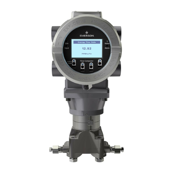
Base Firmware The Emerson FB1200 flow computer measures pressure, differential pressure, and temperature for one or two meter runs of natural gas. This manual describes how to install and configure the Emerson FB1200 flow computer hardware. For information on using the FBxConnect configuration software, see the online help that accompanies FBxConnect. - Page 8 Emerson FB1200 Flow Computer Instruction Manual D301782X012 July 2017 Figure 1-1: FB1200 Flow Computer HMI module Front end cap (cover) Data plate Rear end cap (cover) Conduit fittings Enclosure Sensor module Introduction...
-
Page 9: Safety Labels
Failure to do so may result in injury to personnel or cause damage to the equipment. SAFETY FIRST General instructions and safety reminders. Features The FB1200 flow computer includes the following key features: Enclosure suitable for use in Class I Division 1 explosion proof and Ex d Zone 1 flame- proof environments. -
Page 10: Fb1200 Flow Computer Models
Application software supports AGA3, AGA8, ISO 5167, ISO 6976, and API 21.1 calculations in either U.S., metric, or other natural gas standard units. FB1200 Flow Computer Models You can purchase the FB1200 flow computer with or without integrated sensors. 1.3.1 FB1200 Flow Computer – With Sensor... -
Page 11: Fb1200 Flow Computer - No Sensor Version
128 MB FLASH Holds firmware image and configuration files Explosion-proof Enclosure The FB1200 includes an explosion-proof enclosure. The enclosure consists of the main housing, two threaded covers, and four conduit entry points. The four conduit entry points are ¾ in NPT pipe threaded holes that permit entry of field conduit for I/O and communication wiring. - Page 12 (cover). The FB1200 has North American certification for Class I Division 1 Groups C and D (explosion proof) and Class I Division 2 Groups A, B, C and D (non-incendive) hazardous locations or non-hazardous locations.
-
Page 13: Power Options
Important Only use batteries supplied with the flow computer or sold by Emerson Remote Automation Solutions as spare parts for this flow computer. If you substitute a battery you obtain elsewhere you will void your certification unless it is the identical part from the same manufacturer as that supplied with the flow computer from Emerson. -
Page 14: Human-Machine Interface (Hmi) Module
Emerson FB1200 Flow Computer Instruction Manual D301782X012 July 2017 Human-Machine Interface (HMI) Module The flow computer includes an HMI module with an optional liquid crystal display (LCD) for local operator access to the device. The LCD, if present, presents a series of menus that sequentially display the current values of particular process variables. -
Page 15: Software Tools
1.12 Base Firmware The base firmware in the FB1200 flow computer measures pressure (P), differential pressure (DP), and temperature (T) for a one or two meter runs. It performs gas flow calculations based on those inputs in either U.S., metric, or natural gas international units. FBxConnect configuration software enables you to configure the various features and functions of the firmware. - Page 16 Emerson FB1200 Flow Computer Instruction Manual D301782X012 July 2017 NX-19 1962/MOD/VDI/VDE 2040 ISO 12213 2009 (Parts 2 and 3) S-GERG 1991 GPA 2172 2009 (Including Saturated Vapor Calculation) ISO 6976 1995 The firmware accepts density general inputs, gas density, base density, and specific gravity from any of the following sources: ...
-
Page 17: Installation
Appendix A contains special information for Class I Division 2 installations; Appendix B contains special information for Class I Division 1 installations. For Europe the FB1200 has certifications for Ex d Zone 1 flame-proof and for Ex nA Zone 2 non- sparking installations and non-hazardous locations only. Appendix C contains special information for Ex nA Zone 2 installations;... -
Page 18: Required Tools
Emerson FB1200 Flow Computer Instruction Manual D301782X012 July 2017 Table 2-1: Environmental Specifications Specification Range Ambient Temperature -40°C to +80 °C (-40 °F to +176 °F ) - no battery, C1D1/C1D2 -40°C to +60 °C (-40°F to +140 °F ) – lead acid battery, C1D1/C1D2 -40°C to +80 °C (-40 °F to +176 °F ) –... -
Page 19: Site Considerations
If your unit includes the optional Mobile SCADA ensure the installation location provides line-of-sight access to the transceiver. Figure 2-1: FB1200 Dimensions – MVT Version Installation... - Page 20 Emerson FB1200 Flow Computer Instruction Manual D301782X012 July 2017 Figure 2-2: FB1200 Dimensions – No Sensor Version Installation...
-
Page 21: General Wiring Guidelines
Emerson FB1200 Flow Computer Instruction Manual D301782X012 July 2017 General Wiring Guidelines The flow computer’s pluggable terminal blocks use compression-type terminals. The 5.08 mm pitch terminal blocks accommodate wire between 28 and 12 AWG; the 3.81 mm pitch terminal blocks accommodate wire between 28 and 14 AWG. -
Page 22: Removing The Front Or Rear End Caps
Emerson FB1200 Flow Computer Instruction Manual D301782X012 July 2017 Figure 2-4: Retaining Clamp in Place To loosen or tighten the screw, use a 3mm hexagonal wrench. When tightening, torque to 12 in-lbs (1.4 N m). Figure 2-5: Retaining Clamp and Screw 2.6.2... -
Page 23: Replacing The Front Or Rear End Caps
Emerson FB1200 Flow Computer Instruction Manual D301782X012 July 2017 Remove the retaining clamp (if present). (See Section 2.6.1) Grasp the end cap (front or rear). Figure 2-7: Front (left) and Rear (right) End caps Unscrew the end cap turning it counter-clockwise until it comes off. Set it aside in a safe location. -
Page 24: Mounting The Enclosure
Only use bolts supplied with the flow computer or sold by Emerson Remote Automation Solutions as spare parts. Refer to the figure for common flow computer assemblies with the bolt length required for proper flow computer installation. - Page 25 Emerson FB1200 Flow Computer Instruction Manual D301782X012 July 2017 Figure 2-11: Transmitter with Traditional Flange and Optional Flange Adapters Use the following bolt installation procedure: Carbon steel bolts do not require lubrication. Stainless steel bolts are factory-coated with a lubricant to ease installation. Do not apply any additional lubricant when installing either type of bolt.
-
Page 26: O-Rings With Flange Adapters
Emerson FB1200 Flow Computer Instruction Manual D301782X012 July 2017 Figure 2-12: Proper Bolt Installation Bolt Sensor module 2.7.2 O-rings with Flange Adapters DANGER Failure to install proper flange adapter O-rings may cause process leaks, which can result in death or serious injury. Only use the O-ring that is designed for its specific flange adapter. -
Page 27: Direct Mount
Emerson FB1200 Flow Computer Instruction Manual D301782X012 July 2017 2.7.3 Direct Mount Direct mount installations use either a traditional mounting kit or a coplanar mounting kit. Mount the flow computer directly to the natural gas pipeline only if the pipeline includes a process manifold. -
Page 28: Indirect Mount
Emerson FB1200 Flow Computer Instruction Manual D301782X012 July 2017 Figure 2-15: Coplanar Mounting Kit Tubular L-shaped bracket ® 3/8-16 x 1 ½ in wire screw (2) – Apply Killark LUBG-6 Thread Lubricant to threads. Torque screws to 30 in-lbs (3.4 N m) Split 5/16 washer (2) 5/16-18 keps nut (2). -
Page 29: Rotating The Housing
Emerson FB1200 Flow Computer Instruction Manual D301782X012 July 2017 Figure 2-16: Inline Mounting Kit Pipe mounting bracket 2 ½ inch x 5/18-18 thread 300-series U-bolt 5/16 flat lock washer (2) 5/16-18 300 series passivate hex nut (2) - Apply Loctite 222 Low Strength Purple Threadlocker to threads. - Page 30 Emerson FB1200 Flow Computer Instruction Manual D301782X012 July 2017 Figure 2-17: Housing Rotation Set Screw (1 each side) Set Screw (one each side) DANGER EXPLOSION HAZARD: Ensure the area in which you perform this operation is non-hazardous. Performing this operation in a hazardous area could result in an explosion.
-
Page 31: Grounding The Device
Emerson FB1200 Flow Computer Instruction Manual D301782X012 July 2017 Grounding the Device The flow computer includes a grounding lug on the terminal plate. Figure 2-18: Ground Lug Ground Lug DANGER EXPLOSION HAZARD: Ensure the area in which you perform this operation is non-hazardous. -
Page 32: Terminal Plate
Emerson FB1200 Flow Computer Instruction Manual D301782X012 July 2017 Terminal Plate The terminal plate includes the various terminal blocks (TB) for power and I/O connections. The terminal plate’s appearance varies depending upon whether or not you have the optional 6- channel expansion I/O board installed with 3.81 pitch connections;... -
Page 33: Power Modes
2.10 Power Modes To keep power consumption to a minimum, especially for remote sites, the FB1200 can run in two different power modes – Low Power Mode (4 or 8 MHz CPU clock speed) or Standard Power Mode (60 MHz CPU clock speed). -
Page 34: July
Emerson FB1200 Flow Computer Instruction Manual D301782X012 July 2017 mode when the communication period is over. A serial connection to a remote 4088B MVS can occur in low power mode. The local display (HMI module) with Mobile SCADA and WiFi uses additional power. You can configure it in FBxConnect to shut down after a period of inactivity. -
Page 35: Standard Power Mode
July 2017 2.10.2 Standard Power Mode When serial communication is active (other than to a remote 4088B MVS) the FB1200 operates in standard power mode. The unit also uses standard power mode when: The HMI module display is ON ... -
Page 36: Connecting Power
Emerson FB1200 Flow Computer Instruction Manual D301782X012 July 2017 2.11 Connecting Power Power can come from an external DC supply, or a lead acid battery pack with a solar panel. See Section 2.12.4 for information on solar power connections. Power connections are made through conduit fittings to the terminal plate. Remove the rear end cap for access to the terminal plate. -
Page 37: Connecting Battery Power
Emerson FB1200 Flow Computer Instruction Manual D301782X012 July 2017 2.11.2 Connecting Battery Power DANGER EXPLOSION HAZARD: Ensure the area in which you perform this operation is non-hazardous. Performing this operation in a hazardous area could result in an explosion. When power comes from an internal battery pack, the battery pack plugs into one of two connectors. -
Page 38: Attach Mounting Hardware To The Solar Panel
Emerson FB1200 Flow Computer Instruction Manual D301782X012 July 2017 Wiring power to the solar panel. Setting the tilt angle of the panel for maximum solar exposure. 2.12.1 Attach Mounting Hardware to the Solar Panel DANGER EXPLOSION HAZARD: Ensure the area in which you perform this operation is non-hazardous. -
Page 39: Mounting The Solar Panel (Integral Mount)
Emerson FB1200 Flow Computer Instruction Manual D301782X012 July 2017 5/16 flat spring lock washer (2) only one visible; placed on bolt between washer and mounting bracket 2.12.2 Mounting the Solar Panel (Integral Mount) DANGER EXPLOSION HAZARD: Ensure the area in which you perform this operation is non-hazardous. - Page 40 Emerson FB1200 Flow Computer Instruction Manual D301782X012 July 2017 Figure 2-23: Integral Mounted Solar Panel 6V, 6W solar panel aluminum tilt bracket (2) 10-32 x ½ pan head screw (4). 5/16 flat washer (4); only two visible in this graphic 5/16-18 x .75 LG hex head bolt (2)
-
Page 41: Mounting The Solar Panel (Remote Mount)
Emerson FB1200 Flow Computer Instruction Manual D301782X012 July 2017 2.12.3 Mounting the Solar Panel (remote mount) DANGER EXPLOSION HAZARD: Ensure the area in which you perform this operation is non-hazardous. Performing this operation in a hazardous area could result in an explosion. -
Page 42: Connecting Solar Power
Emerson FB1200 Flow Computer Instruction Manual D301782X012 July 2017 2.12.4 Connecting Solar Power DANGER EXPLOSION HAZARD: Ensure the area in which you perform this operation is non-hazardous. Performing this operation in a hazardous area could result in an explosion. When power comes from a solar panel/lead acid battery combination, connect using the +SPIN and –SPIN terminals and standard copper wire (#18 AWG minimum). -
Page 43: Adjusting The Optional Solar Panel Tilt Angle
Emerson FB1200 Flow Computer Instruction Manual D301782X012 July 2017 2.12.5 Adjusting the Optional Solar Panel Tilt Angle DANGER EXPLOSION HAZARD: Ensure the area in which you perform this operation is non-hazardous. Performing this operation in a hazardous area could result in an explosion. -
Page 44: Connecting Communication Ports
Emerson FB1200 Flow Computer Instruction Manual D301782X012 July 2017 Table 2-6: Solar Panel Tilt Angle Latitude Installation Angle 0 to 4 10 from horizontal 5 to 20 Add 5 from the local latitude 21 to 45 Add 10 from the local latitude 46 to 65... - Page 45 Emerson FB1200 Flow Computer Instruction Manual D301782X012 July 2017 When connecting COM1 to another device using RS-232, use a cable with configurations as shown Figure 2-27: Figure 2-27: Connecting a Device to COM1 Using RS-232 Note: Cable for units with optional I/O shown on top; cable for units without optional I/O shown below.
- Page 46 Emerson FB1200 Flow Computer Instruction Manual D301782X012 July 2017 When connecting COM1 to another device using RS-422, use a cable with configurations as shown Figure 2-28: Figure 2-28: Connecting a Device to COM1 Using RS-422 Note: Cable for units with optional I/O shown on top; cable for units without optional I/O shown below.
- Page 47 Emerson FB1200 Flow Computer Instruction Manual D301782X012 July 2017 When connecting COM1 to another device using RS-485, use a cable with configurations as shown Figure 2-29: Figure 2-29: Connecting a Device to COM1 Using RS-485 Note: Cable for units with optional I/O shown on top; cable for units without optional I/O shown below.
-
Page 48: Connecting To Com2 And Com3
Emerson FB1200 Flow Computer Instruction Manual D301782X012 July 2017 2.13.2 Connecting to COM2 and COM3 COM2 and COM3 operate identically. Each can be configured for either RS-232 or RS-485 communication. When connecting COM2 or COM3 to an RS-232 port on another device (a PC or another... - Page 49 Emerson FB1200 Flow Computer Instruction Manual D301782X012 July 2017 Figure 2-31: Connecting a Device to COM2 or COM3 Using RS-232 – No optional I/O COM2 does not have its own GND terminal. Use either GND terminal on the COM1 terminal block.
- Page 50 Emerson FB1200 Flow Computer Instruction Manual D301782X012 July 2017 When connecting COM2 or COM3 to an RS-485 port on another device (for example, a transmitter), use a cable with configurations as shown in Figure 2-32: Figure 2-32: Connecting a Device to COM2 or COM3 Using RS-485 – Optional I/O present...
- Page 51 Emerson FB1200 Flow Computer Instruction Manual D301782X012 July 2017 Figure 2-33: Connecting a Device to COM2 or COM3 Using RS-485 – No optional I/O COM2 does not have its own GND terminal. Use either GND terminal on the COM1 terminal block.
-
Page 52: Ethernet Port
Emerson FB1200 Flow Computer Instruction Manual D301782X012 July 2017 2.13.3 Ethernet Port The Ethernet port is a standard 8-pin 10/100Base-T RJ-45 modular connector located on the terminal plate. Figure 2-34: Location of Ethernet Port Ethernet Port Note The default IP address for the Ethernet port is 192.168.1.10. - Page 53 Emerson FB1200 Flow Computer Instruction Manual D301782X012 July 2017 Note If you ordered Ethernet, the unit ships with Ethernet enabled. If you need to operate the device in lower power mode, you must disable Ethernet. Jumper J10 on the CPU module determines whether Ethernet is enabled or Ethernet is disabled (lower power mode).
-
Page 55: I/O Configuration And Wiring
Connecting a Rosemount 4088B Transmitter For Use in a Second Meter Run I/O in the FB1200 flow computer comes from the integrated MVT sensor and RTD connector, the CPU board, as well as from the optional 6-channel expansion I/O board. - Page 56 Emerson FB1200 Flow Computer Instruction Manual D301782X012 July 2017 Figure 3-1: Base I/O On CPU (when optional I/O also present) I/O Configuration and Wiring...
- Page 57 Emerson FB1200 Flow Computer Instruction Manual D301782X012 July 2017 Figure 3-2: Base I/O On CPU (No optional I/O present) I/O Configuration and Wiring...
-
Page 58: Analog Inputs
Figure 3-3: Optional 6-channel expansion I/O board Analog Inputs The FB1200 flow computer includes two on-board channels you can individually configure as either analog inputs (AI) or analog outputs (AO). In addition, if you purchased the optional 6-channel I/O Configuration and Wiring... -
Page 59: Ai Wiring
Emerson FB1200 Flow Computer Instruction Manual D301782X012 July 2017 expansion I/O board, there are two additional channels you can individually configure as either AIs or AOs. Note No external resistor is required for a current (mA) device. You can apply a 250 ohm resistor using analog input configuration selections in FBxConnect. - Page 60 Emerson FB1200 Flow Computer Instruction Manual D301782X012 July 2017 Figure 3-5: 1-5 V Analog Input (AI) Wiring (Base I/O when optional I/O also present) Note: Analog input wiring for AIAO2 shown. AIAO1 and AIAO2 share same GND terminal. Figure 3-6:...
- Page 61 Emerson FB1200 Flow Computer Instruction Manual D301782X012 July 2017 Figure 3-7: 4-20 mA Analog Input (AI) Wiring – (Optional 6-channel expansion I/O board) Note: Analog input wiring for AIAO3 shown. AIAO3 and AIAO4 share same GND terminal. Figure 3-8: 1-5 V Analog Input (AI) Wiring (Optional 6-channel expansion I/O board) Note: Analog input wiring for AIAO3 shown.
-
Page 62: Analog Outputs
July 2017 Analog Outputs The FB1200 flow computer includes two on-board channels you can individually configure as either analog outputs (AO) or analog inputs. In addition, if you purchased the optional 6-channel expansion I/O board, there are two additional channels you can individually configure as either AOs or AIs. - Page 63 Emerson FB1200 Flow Computer Instruction Manual D301782X012 July 2017 Figure 3-10: Analog Output (AO) Wiring – (Base I/O – when optional I/O not present) Figure 3-11: Analog Output (AO) Wiring (Optional 6-channel expansion I/O board) Note: Analog input wiring for AIAO4 shown. AIAO3 and AIAO4 share same GND terminal.
-
Page 64: Digital Inputs
July 2017 Digital Inputs Depending upon how you ordered it, the FB1200 flow computer includes either two or six channels you can individually configure as digital inputs (DI), digital outputs (DO), or pulse inputs (PI). When configured as digital inputs, the channels have the following characteristics:... - Page 65 Emerson FB1200 Flow Computer Instruction Manual D301782X012 July 2017 Figure 3-13: Digital Input (DI) Wiring - (Base I/O -when optional I/O not present) Figure 3-14: Digital Input (DI) Wiring - (Optional 6-channel expansion I/O board) Note: Digital input wiring for DIDO6 shown. DIDO5 and DIDO6 share same GND terminal. DIDO3 and DIDO4 share a different GND terminal.
-
Page 66: Digital Outputs
D301782X012 July 2017 Digital Outputs Depending upon how you ordered it, the FB1200 flow computer includes two or six channels you can configure as digital outputs (DO), digital inputs (DI) or pulse inputs (PI). Note When using a digital output to drive an inductive load (such as a relay coil), place a suppression diode across the load. - Page 67 Emerson FB1200 Flow Computer Instruction Manual D301782X012 July 2017 Figure 3-15: Digital Output (DO) Wiring - (Base I/O - optional I/O also present) Note: Digital output wiring for DIDO2 shown. DIDO1 and DIDO2 share same GND terminal. I/O Configuration and Wiring...
- Page 68 Emerson FB1200 Flow Computer Instruction Manual D301782X012 July 2017 Figure 3-16: Digital Output (DO) Wiring - (Base I/O - optional I/O not present) Figure 3-17: Digital Output (DO) Wiring - (Optional 6-channel mixed I/O board) Note: Digital output wiring for DIDO4 shown. DIDO3 and DIDO4 share same GND terminal. DIDO5 and DIDO6 share a different GND terminal.
-
Page 69: Pulse Inputs
July 2017 Pulse Inputs The FB1200 flow computer includes two channels that can be individually configured as either pulse inputs (PI), digital inputs (DI), or digital outputs (DO). When configured as pulse inputs, the PI channels have the following characteristics:... - Page 70 Emerson FB1200 Flow Computer Instruction Manual D301782X012 July 2017 Figure 3-19: Pulse Input (PI) Wiring - (Base I/O - when optional I/O not present) Figure 3-20: Pulse Input (PI) Wiring - (Optional I/O Board) Note: Pulse input wiring for PIDIDO5 shown. PIDIDO5 and PIDIDO6 share same GND terminal. PIDIDO3 and PIDIDO4 share same GND terminal.
-
Page 71: Connecting The Rtd
Emerson FB1200 Flow Computer Instruction Manual D301782X012 July 2017 Connecting the RTD DANGER EXPLOSION HAZARD: Ensure the area in which you perform this operation is non-hazardous. Performing this operation in a hazardous area could result in an explosion. RTD connections reside on the terminal plate under the rear end cap. The flow computer supports 2-wire, 3-wire, and 4-wire operation. - Page 72 Emerson FB1200 Flow Computer Instruction Manual D301782X012 July 2017 Figure 3-22: Wiring for 2-Wire, 3-Wire, and 4-Wire RTD (Units without Optional I/O) I/O Configuration and Wiring...
-
Page 73: Connecting A Rosemount 4088B Transmitter For Use In A Second Meter Run
Emerson FB1200 Flow Computer Instruction Manual D301782X012 July 2017 Connecting a Rosemount 4088B Transmitter For Use in a Second Meter Run Data for the second run comes from an external transmitter such as the Rosemount 4088B. Figure 3-23: Connecting a 4088B Transmitter for a Second Meter Run See the Rosemount™... - Page 74 Emerson FB1200 Flow Computer Instruction Manual D301782X012 July 2017 Using twisted pair wire, connect the RS-485 terminals for COM3 to the RS-485 terminals on the 4088B as shown in the graphic. Set switches on the 4088B for bus termination, or use a 120 ohm resistor.
-
Page 75: Operation
Emerson FB1200 Flow Computer Instruction Manual D301782X012 July 2017 Section 4: Operation This section covers the following topics: Powering Up/Powering Down the Device Establishing Communications Communicating using the HMI Module This section describes day-to-day operation of the flow computer including how to turn it on and off and how to communicate with it. -
Page 76: Communicating With A Laptop Using One Of The Serial Ports
Decide which communication protocol you will use. This could be DNP3, ROC, or BSAP. See these documents for more information: Emerson FB Flow Computer DNP3 Protocol Specifications Manual (D301806X012) ROC Protocol Specifications Manual (for Emerson FBx-series) (D301828X012) ... -
Page 77: Communicating With A Laptop Wirelessly
Emerson FB1200 Flow Computer Instruction Manual D301782X012 July 2017 DANGER EXPLOSION HAZARD: Ensure the area in which you perform this operation is non-hazardous. Performing this operation in a hazardous area could result in an explosion. 1. Connect a Category 5 shielded cable between an Ethernet port on your laptop and an Ethernet switch for your network. -
Page 78: Communicating Using The Hmi Module
Emerson FB1200 Flow Computer Instruction Manual D301782X012 July 2017 When finished, log off the flow computer and disconnect from the wireless network. Communicating using the HMI Module You must have purchased the flow computer with the HMI module version that includes the optional display. - Page 79 Emerson FB1200 Flow Computer Instruction Manual D301782X012 July 2017 Figure 4-2: Infrared (IR) Button Location Left Infrared (IR) Button Down Infrared (IR) Button Up Infrared (IR) Button Right Infrared (IR) Button Note When using the IR buttons, aim your finger at the round spot just below the arrow.
- Page 80 Emerson FB1200 Flow Computer Instruction Manual D301782X012 July 2017 Table 4-1: Infrared (IR) Buttons on HMI Module Button Use to Screen Saver Mode Tap once to move (UP) or (DOWN) one item through list of parameters. Hold to stay on current parameter.
-
Page 81: Section 5: Service And Troubleshooting
Important Only use batteries supplied with the flow computer or sold by Emerson Remote Automation Solutions as spare parts for this flow computer. If you substitute a battery you obtain elsewhere you will void your certification unless it is the identical part from the same manufacturer as that supplied with the flow computer from Emerson. -
Page 82: Returning The Unit For Repairs
Other types of repairs cannot be performed in the field. In those cases, you must ship the unit to an Emerson-authorized repair facility. Contact Emerson Remote Automation Solutions for a return authorization number and instructions for where to ship the unit. -
Page 83: Interpreting The Status Leds
Emerson FB1200 Flow Computer Instruction Manual D301782X012 July 2017 Interpreting the Status LEDs There are four (4) status LEDs on the flow computer. The meaning of each LED varies depending upon the color displayed or whether the LED flashes. Figure 5-2: LED Locations... - Page 84 Emerson FB1200 Flow Computer Instruction Manual D301782X012 July 2017 CPU booting or CPU has not yet Flashing YELLOW recognized HMI module when HMI first powered on; goes off when recognized. Status LED GREEN OK - Normal Unit failed Low power source/change battery soon...
-
Page 85: Switch And Buttons
Emerson FB1200 Flow Computer Instruction Manual D301782X012 July 2017 Switch and Buttons A momentary switch and two push buttons on the HMI module provide trouble-shooting options for the flow computer. DANGER EXPLOSION HAZARD: Never remove end cap(s) in a hazardous location. Removing end cap(s) in a hazardous location could result in an explosion. -
Page 86: Removing/Replacing The Hmi Module
Emerson FB1200 Flow Computer Instruction Manual D301782X012 July 2017 Removing/Replacing the HMI Module You do not need to power down the unit to replace the HMI module. DANGER Ensure the flow computer is in a non-hazardous area. Never remove/replace the HMI module in a hazardous area. -
Page 87: Replacing The Main Battery Pack
Emerson FB1200 Flow Computer Instruction Manual D301782X012 July 2017 Replacing the Main Battery Pack Periodically you must replace the main battery pack. FBxConnect provides a battery life indicator to show the number of days in use. Figure 5-4: Main Battery Pack The device provides two battery connectors, enabling you to hot-swap the battery pack in a non- hazardous location. - Page 88 Emerson FB1200 Flow Computer Instruction Manual D301782X012 July 2017 DANGER EXPLOSION HAZARD: Do not replace batteries unless power has been switched off or the area is known to be non-hazardous. Batteries must only be changed in an area known to be non- hazardous.
-
Page 89: Removing/Replacing The Sram Battery
Emerson FB1200 Flow Computer Instruction Manual D301782X012 July 2017 Align the HMI module with the new battery pack and the tab on the CPU carrier board (bezel). Gently press the assembly on, being careful not to pinch the battery wires. -
Page 90: Upgrading System Firmware
Replace the retaining clamp, if applicable (see Section 2.6.1). Upgrading System Firmware Periodically Emerson releases new system firmware for the flow computer to introduce new features or update system functions. You must know a valid username/password combination for the flow computer to complete this process. - Page 91 Emerson FB1200 Flow Computer Instruction Manual D301782X012 July 2017 Figure 5-7: Firmware Update Dialog Box Select the checkbox in the Selected column to choose the firmware. If you are downloading the same version that is already installed on the device, select Download Even If Unchanged.
-
Page 93: Appendix A: Special Instructions For Class I Division 2 Locations
An RTD may be supplied with the Emerson FB1200 flow computer. Connection to the RTD is approved as a non-incendive circuit so that Division 2 wiring methods are not required. - Page 94 Emerson FB1200 Flow Computer Instruction Manual D301782X012 July 2017 Figure A-1: Data Plate (NO BATTERY) – Class I Division 2 Non-incendive (UL) Special Instructions for Class I Division 2 Locations...
- Page 95 Emerson FB1200 Flow Computer Instruction Manual D301782X012 July 2017 Figure A-2: Data Plate (LEAD ACID BATTERY) – Class I Division 2 Non-incendive (UL) Special Instructions for Class I Division 2 Locations...
-
Page 97: Appendix B: Special Instructions For Class I Division 1 Locations
An RTD may be supplied with the Emerson FB1200 flow computer. Connection to the RTD is approved as a non-incendive circuit. - Page 98 Emerson FB1200 Flow Computer Instruction Manual D301782X012 July 2017 DANGER EXPLOSION HAZARD: Do not disconnect equipment unless power has been removed or the area is known to be non-hazardous. DANGER EXPLOSION HAZARD: Substitution of any components may impair suitability for Class I, Division 1 or Class I, Division 2.
- Page 99 Emerson FB1200 Flow Computer Instruction Manual D301782X012 July 2017 Figure B-1: Data Plate (NO BATTERY) – Class I Division 1 Explosion Proof (UL) Special Instruction for Class I Division 1 Locations...
- Page 100 Emerson FB1200 Flow Computer Instruction Manual D301782X012 July 2017 Figure B-2: Data Plate (LEAD ACID BATTERY) – Class I Division 1 Explosion Proof (UL) Special Instructions for Class I Division 1 Locations...
-
Page 101: Appendix C: Atex Non-Sparking Zone 2 Certifications
D301782X012 July 2017 Appendix C: ATEX Non-Sparking Zone 2 Certifications This appendix includes notes on ATEX certifications. For full details, please refer to the Emerson FB1200 Flow Computer Safe Use Instructions (D301769X012). Follow these Conditions of Safe Use: Provision shall be made to prevent the rated voltage being exceeded by the transient disturbances of more than 140% of the peak rated voltage. - Page 102 Emerson FB1200 Flow Computer Instruction Manual D301782X012 July 2017 Figure C-1: Data Plate – ATEX nA Non-Sparking ATEX Non-Sparking Zone 2 Certifications...
-
Page 103: Appendix D: Atex Flame-Proof Zone 1 Certifications
July 2017 Appendix D: ATEX Flame-Proof Zone 1 Certifications The data plate and certain conditions of use are shown below. For full details refer to the Emerson FB1200 Flow Computer Safe Use Instructions (D301769X012). Figure D-1: Data Plate – ATEX Ex d Flame-proof... - Page 104 Specific conditions of use / Schedule of Limitations: Contact your authorized sales and service representative for any maintenance or repair beyond the maintenance of the FB1200 flow computer. Do not alter or disassemble any of the flameproof joints of the FB1200 flow computer.
-
Page 105: Index
Emerson FB1200 Flow Computer Instruction Manual D301782X012 July 2017 Index 4 4088B transmitter ..........67 battery ..............31 4088B transmitter ........... 67 DC power ............30 A Ethernet .............. 46 I/O ............... 49 Analog Inputs ............52 ports ..............38 Analog Outputs ............ -
Page 106: D301782X012 July
3-1. Base I/O On CPU (when optional I/O also Version ............... 4 present) ............50 1-3. FB1200 Flow Computer – No Sensor Version ... 5 1-4. HMI Module with LCD ........8 3-2. Base I/O On CPU (No optional I/O present) ..51 1-5. - Page 107 Emerson FB1200 Flow Computer Instruction Manual D301782X012 July 2017 5-3. Captive Fastening Screws ......80 LEDs 5-4. Main Battery Pack .......... 81 meaning of ............77 5-5. Removing the Battery Pack ......82 M 5-6. Removing/Replacing the Coin Cell Battery ..84 Memory 5-7.
- Page 108 Emerson FB1200 Flow Computer Instruction Manual D301782X012 July 2017 Serial communications..........70 2-4. Typical Power Usage– Low Power Mode ..28 Service ..............75 2-5. Typical Power Usage – Standard Power Mode ................ 29 Site considerations ........... 13 Software Tools ............9 2-6.
- Page 110 Emerson Automation Solutions Remote Automation Solutions Emerson FZE P.O. Box 17033 © 2017 Remote Automation Solutions, a business unit of Emerson Automation Solutions. All Jebel Ali Free Zone – South 2 rights reserved. Dubai U.A.E. This publication is for informational purposes only. While every effort has been made to ensure...