Table of Contents
Advertisement
Advertisement
Table of Contents

Related Manuals for D-Link DGS-1100-10MP


Summary of Contents for D-Link DGS-1100-10MP
- Page 1 www.use-ip.co.uk 01304 827609...
- Page 2 Reproduction in any manner whatsoever without the written permission of D-Link Corporation is strictly forbidden. Trademarks used in this text: D-Link and the D-Link logo are trademarks of D-Link Corporation; Microsoft and Windows are registered trademarks of Microsoft Corporation. Other trademarks and trade names may be used in this document to refer to either the entities claiming the marks and names or their products.
-
Page 3: Table Of Contents
Standard Mode and Surveillance Mode ..........................1 Other Documentation ................................. 1 Conventions ..................................1 Notes, Notices, and Cautions ............................2 Product Introduction ..............................3 DGS-1100-10MP ................................4 Front Panel ................................... 4 Rear Panel ..................................4 DGS-1100-10MPP ................................6 Front Panel ................................... 6 Rear Panel .................................. - Page 4 DGS-1100 MP/MPP Series Switch Web UI Reference Guide PoE Information................................37 10. PoE Scheduling ................................39 11. Time ....................................41 Clock Settings .................................. 41 SNTP Settings ................................. 41 12. Surveillance Settings ..............................43 13. Surveillance Log................................46 14. Health Diagnostic ................................ 47 15.
-
Page 5: Introduction
The documents below are a further source of information in regards to configuring and troubleshooting the switch. All the documents are available either from the CD, bundled with this switch, or from the D-Link website. Other documents related to this switch are: •... -
Page 6: Notes, Notices, And Cautions
D-Link DGS-1100 MP/MPP Series Switch User Manual Notes, Notices, and Cautions Below are examples of the three types of indicators used in this manual. When administering your switch using the information in this document, you should pay special attention to these indicators. -
Page 7: Product Introduction
D-Link DGS-1100 MP/MPP Series Switch User Manual Product Introduction The DGS-1100 MP/MPP series Smart Switch is the world’s first PoE switch with ONVIF support. This allows it to recognize ONVIF devices and integrate seamlessly with your surveillance network. Various power budgets, support for high powered PoE standards (MPP series) and 6 KV surge protection make the DGS-1100 MP/MPP series a critical part of your surveillance infrastructure. -
Page 8: Dgs-1100-10Mp
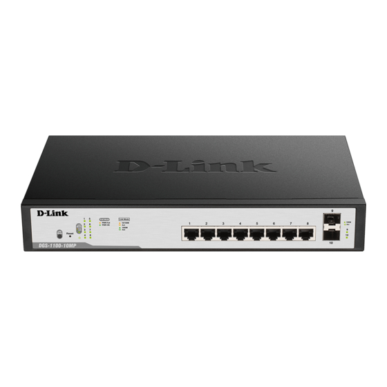
D-Link DGS-1100 MP/MPP Series Switch User Manual DGS-1100-10MP 8-Port 10/100/1000 Mbps + 2-Port SFP 1000 Mbps PoE switch Front Panel Figure 2-1 - DGS-1100-10MP Front Panel Power LED: The Power LED lights up when the switch is connected to a power source. - Page 9 D-Link DGS-1100 MP/MPP Series Switch User Manual Power: The power port is where to connect the AC power cord. CAUTION: The SFP ports should use UL listed Optical Transceiver product, Rated Laser Class I. 3.3Vdc. CAUTION: This equipment is to be connected only to PoE networks without...
-
Page 10: Dgs-1100-10Mpp
D-Link DGS-1100 MP/MPP Series Switch User Manual DGS-1100-10MPP 8-Port 10/100/1000 Mbps + 2-Port SFP 1000 Mbps PoE switch Front Panel Figure 2-3 – DGS-1100-10MPP Front Panel Power LED: The Power LED lights up when the switch is connected to a power source. - Page 11 D-Link DGS-1100 MP/MPP Series Switch User Manual Power: Connect the supplied AC power cable to this port. CAUTION: The SFP ports should use UL listed Optical Transceiver product, Rated Laser Class I. 3.3Vdc. CAUTION: This equipment is to be connected only to PoE networks without...
-
Page 12: Dgs-1100-26Mp
D-Link DGS-1100 MP/MPP Series Switch User Manual DGS-1100-26MP 24-Port 10/100/1000 Mbps + 2-Port Combo 1000BASE-T/SFP PoE switch Front Panel Figure 2-5 – DGS-1100-26MP Front Panel Power LED: The Power LED lights up when the switch is connected to a power source. -
Page 13: Rear Panel
D-Link DGS-1100 MP/MPP Series Switch User Manual Rear Panel Figure 2-6 – DGS-1100-26MP Rear Panel Power: Connect the supplied AC power cable to this port. CAUTION: The SFP ports should use UL listed Optical Transceiver product, Rated Laser Class I. 3.3Vdc. -
Page 14: Dgs-1100-26Mpp
D-Link DGS-1100 MP/MPP Series Switch User Manual DGS-1100-26MPP 24-Port 10/100/1000 Mbps + 2-Port Combo 1000BASE-T/SFP PoE switch Front Panel Figure 2-7 – DGS-1100-26MPP Front Panel Power LED: The Power LED lights up when the switch is connected to a power source. -
Page 15: Rear Panel
D-Link DGS-1100 MP/MPP Series Switch User Manual Rear Panel Figure 2-8 – DGS-1100-26MPP Rear Panel Power: Connect the supplied AC power cable to this port. CAUTION: The SFP ports should use UL listed Optical Transceiver product, Rated Laser Class I. 3.3Vdc. -
Page 16: Hardware Installation
D-Link DGS-1100 MP/MPP Series Switch User Manual Hardware Installation This chapter provides unpacking and installation information for the D-Link switch. Step 1: Unpacking Open the shipping carton and carefully unpack its contents. Please consult the packing list located below to make sure all items are present and undamaged. If any item is missing or damaged, please contact your local D-Link reseller for a replacement. - Page 17 D-Link DGS-1100 MP/MPP Series Switch User Manual CAUTION: Ensure the power cable is disconnected before installing the switch. To install, attach the mounting brackets to the switch’s side panels (one on each side) and secure them with the screws provided.
-
Page 18: Step 3: Plugging In The Ac Power Cord
D-Link DGS-1100 MP/MPP Series Switch User Manual E) Reliable Earthing - Reliable earthing of rack-mounted equipment should be maintained. Particular attention should be given to supply connections other than direct connections to the branch circuit (e.g. use of power strips)."... - Page 19 D-Link DGS-1100 MP/MPP Series Switch User Manual Step 5: Attach the terminal lug ring at the other end of the grounding cable to an appropriate grounding stud or bolt on rack where the switch is installed. Step 6: Verify if the connections at the ground connector on the switch and the rack are securely attached.
-
Page 20: Web-Based Switch Configuration
D-Link Network Assistant DNA (D-Link Network Assistant) included on the installation CD is a program for discovering DGS- 1100 MP/MPP Series switches with the same L2 network segment connected to your PC. This tool can support windows 2000, XP, Vista, and Windows 7. -
Page 21: Logging Onto The Web User Interface
D-Link DGS-1100 MP/MPP Series Switch User Manual Connect the Ethernet cable to any of the ports on the front panel of the switch and to the Ethernet port on the PC. Logging onto the Web User Interface To access the Web UI, simply open a web browser and enter the switch’s default IP address into the address bar. -
Page 22: Smart Wizard
D-Link DGS-1100 MP/MPP Series Switch User Manual Smart Wizard The Smart Wizard is a configuration utility that is launched the first time the Web UI is accessed. It allows users to configure basic settings such as the switch mode, management IP and password. It can also be used to switch between Standard Mode and Surveillance Mode Web UI types. - Page 23 D-Link DGS-1100 MP/MPP Series Switch User Manual Click the Exit button to discard the changes made, exit the Smart Wizard, and continue to the Standard Mode Web UI. Click the Next button to accept the changes made and continue to the next step.
- Page 24 D-Link DGS-1100 MP/MPP Series Switch User Manual The fields that can be configured are described below: Parameter Description Static Select this option to manually configure and use IP address settings on this switch. DHCP Select this option to obtain IP address settings from a DHCP server.
- Page 25 D-Link DGS-1100 MP/MPP Series Switch User Manual Click the Exit button to discard the changes made, exit the Smart Wizard, and continue to the Standard Mode Web UI. Click the Apply & Save button to accept the changes made, and then continue to the Web UI.
-
Page 26: Web User Interface
D-Link DGS-1100 MP/MPP Series Switch User Manual Web User Interface When you complete the Surveillance Mode Smart Wizard you will be presented with the following screen: Figure 4-5 Congratulations window Scroll to the bottom of the page and click the OK button to continue to the Web UI. -
Page 27: Areas Of The User Interface
D-Link DGS-1100 MP/MPP Series Switch User Manual Areas of the User Interface The figure below shows the user interface. Two distinct areas divide the user interface, as described in the table. AREA 1 AREA 2 Figure 4-6 Main Web UI Window... -
Page 28: Surveillance Overview
D-Link DGS-1100 MP/MPP Series Switch User Manual Surveillance Overview This loads automatically when you log-in to the switch and contains two tabs; Surveillance Topology and Device Information. To return to the Surveillance Overview page after viewing other pages, click the model number of the switch at the top of the navigation menu. - Page 29 D-Link DGS-1100 MP/MPP Series Switch User Manual The icon descriptions are as follows: Icon Description The total number of IP-Cameras detected. The total number of NVRs detected. The number of warnings on the system. Consult the Surveillance Log and Health Diagnostic pages for more information.
- Page 30 D-Link DGS-1100 MP/MPP Series Switch User Manual One ONVIF IP-Camera and multiple NVRs discovered on this port. This port is set as uplink port and it is link up. This port is set as uplink port and it is link down.
-
Page 31: Enabling And Disabling Poe
D-Link DGS-1100 MP/MPP Series Switch User Manual Enabling and Disabling PoE CAUTION: Before connecting the Powered Device (PD) and enabling 60/70 W PoE, make sure it supports IEEE 802.3bt, as otherwise it will become damaged. The power status of each port can be changed by clicking the power icon on each port. The default setting for PoE is on. -
Page 32: Device Information
D-Link DGS-1100 MP/MPP Series Switch User Manual Device Information This is the second tab on the Surveillance Overview page and is divided into 3 areas; a device information section, PoE utilization section and bandwidth usage section. To view the following window, click on the model number of the switch at the top of the navigation... -
Page 33: Port Information
D-Link DGS-1100 MP/MPP Series Switch User Manual Port Information The Port Information section provides an overview of the port status for each port. This includes the throughput, PoE status, Loopback Detection Status, cable length, power consumption and the devices connected to each port. - Page 34 D-Link DGS-1100 MP/MPP Series Switch User Manual Hover-over each field to get more information about each value. A breakdown of each field is below: Icon Description The port number of the port. The total inbound throughput for the port on the switch (measured in Mbps).
-
Page 35: Group Details
D-Link DGS-1100 MP/MPP Series Switch User Manual Group Details The Group Details page lists the devices connected to a specific port. Only devices that have been recognized as supporting ONVIF or NVRs will be displayed. To view the following window, click on the Port Information link in the navigation menu and then... - Page 36 D-Link DGS-1100 MP/MPP Series Switch User Manual The device description. This can be edited on the IP-Camera Information page or NVR Information page.
-
Page 37: Ip-Camera Information
Hover-over each field to get more information about each value. A breakdown of each field is below: Icon Description The port number of the port. The device icon or photo. A generic photo will displayed for a non-D-Link ONVIF camera. A D-Link-specific photo will be displayed for a D-Link ONVIF camera. - Page 38 D-Link DGS-1100 MP/MPP Series Switch User Manual The total inbound throughput for the port on the switch (measured in Mbps). The PoE consumption of the port. This is listed as one negative integer and one positive integer. A negative value for PoE means that power is being consumed by the port.
-
Page 39: Nvr Information
D-Link DGS-1100 MP/MPP Series Switch User Manual NVR Information The NVR Information section provides information on each NVR connected to the switch. It features the port number, throughput, IP address and information relating to the cameras connected to the NVR, such as the group name, total number of cameras and the port and IP address of each camera. - Page 40 D-Link DGS-1100 MP/MPP Series Switch User Manual with NVR1 having Group Number 1. If an NVR is removed, the Group Numbers will be updated accordingly (if NVR1 is removed then Group Number 2 will become Group Number 1). The number of ONVIF IP-Cameras managed by this NVR.
-
Page 41: Poe Information
D-Link DGS-1100 MP/MPP Series Switch User Manual PoE Information The PoE Information section provides information on the PoE usage of each port. The port number, PoE status, health status, PoE budget and power consumption is listed for each port. It is possible to click on the health status to be re-directed to the Health Diagnostic page. - Page 42 D-Link DGS-1100 MP/MPP Series Switch User Manual Hover-over each field to get more information about each value. A breakdown of each field is below: Icon Description The port number of the port. The PoE status for the port (PoE on or off).
-
Page 43: Poe Scheduling
D-Link DGS-1100 MP/MPP Series Switch User Manual 10. PoE Scheduling PoE Scheduling is a feature which allows you to specify the amount of time that power is delivered to a PoE port. This can be used to save power when devices are not in use, or as a security feature to prevent wireless access from being available outside of business hours, for example. - Page 44 D-Link DGS-1100 MP/MPP Series Switch User Manual Time Profile The Time Profile created above. Click the Apply button to accept the changes made.
-
Page 45: Time
D-Link DGS-1100 MP/MPP Series Switch User Manual 11. Time Clock Settings SNTP Settings Clock Settings This sub-menu is used to configure the time on the switch. To view the following window, go to: Time > Clock Settings in the navigation menu:... - Page 46 D-Link DGS-1100 MP/MPP Series Switch User Manual SNTP State Set the SNTP state. Options are Enabled or Disabled. Pool Interval (30-99999) Set the synchronization interval for SNTP. The default is 720 seconds and the range is 30 – 99999 seconds.
-
Page 47: Surveillance Settings
D-Link DGS-1100 MP/MPP Series Switch User Manual 12. Surveillance Settings The Surveillance Settings page is used to configure the settings for the Surveillance VLAN. This is a VLAN dedicated for IP-Camera and surveillance traffic and can be used to manage surveillance devices on the network. - Page 48 D-Link DGS-1100 MP/MPP Series Switch User Manual The fields that can be configured for the SNMP Host Settings are described below: Parameter Description Host IPv4 Address Enter the IP address of the SNMP Network Management Server (NMS) which will receive SNMP Traps from this device.
- Page 49 IP-Camera discovery process is disabled on these ports. Use the Uplink Port Settings section of the interface to define which ports connect to other switches. NOTE: The default uplink ports of the DGS-1100-10MP/10MPP are port9 and port10. The default uplink ports of DGS-1100-26MP/26MPP are port25 and port26.
-
Page 50: Surveillance Log
D-Link DGS-1100 MP/MPP Series Switch User Manual 13. Surveillance Log The Surveillance Log consists of a list of Syslog messages that have been generated by the switch. Depending on whether a Syslog server has been defined in the Surveillance Settings section, these may be local to the switch or copied to an external logging server. -
Page 51: Health Diagnostic
D-Link DGS-1100 MP/MPP Series Switch User Manual 14. Health Diagnostic The Health Diagnostic page is linked-to by the Port Information and PoE Information pages and displays an overview of the port status. It contains the port number, Loopback Detection status, Cable Link status, PoE Status, Tx/Rx Error Counter, number of Discovered Surveillance Devices on the port (which links to the Group Details page) and the detected cable length. -
Page 52: Save And Tools
D-Link DGS-1100 MP/MPP Series Switch User Manual 15. Save and Tools Firmware Information Firmware Upgrade & Backup Configuration Restore & Backup Reset Reboot System Firmware Information This window is used to show firmware information. To view the following window, click Tools > Firmware Information, as shown below:... -
Page 53: Firmware Backup To Http
D-Link DGS-1100 MP/MPP Series Switch User Manual Parameter Description Source File Enter the source filename and path of the firmware file located on the local PC. Alternatively click the Browse button to navigate to the location of the firmware file located on the local PC. -
Page 54: Configuration Restore & Backup
D-Link DGS-1100 MP/MPP Series Switch User Manual Configuration Restore & Backup Configuration Restore from HTTP This window is used to initiate a configuration restore from a local PC using HTTP. NOTE: If the switch is in HTTPS mode, the firmware or configuration cannot be upgraded using regular HTTP. -
Page 55: Reset
D-Link DGS-1100 MP/MPP Series Switch User Manual Reset This window is used to reset the switch’s configuration to the factory default settings. To view the following window, click Tools > Reset, as shown below: Figure 15-6 Reset window Select the The Switch will be reset to its factory defaults including IP address and stacking information, and the will save, reboot option to reset the switch’s configuration to its factory... - Page 56 D-Link DGS-1100 MP/MPP Series Switch User Manual Figure 15-8 Reboot System - Rebooting window...
-
Page 57: Appendix A - Ethernet Technology
D-Link DGS-1100 MP/MPP Series Switch User Manual 16. Appendix A - Ethernet Technology This chapter will describe the features of the D-Link DGS-1100 MP/MPP Series switch and provide some background information about Ethernet/Fast Ethernet/Gigabit Ethernet switching technology. Gigabit Ethernet Technology Gigabit Ethernet is an extension of IEEE 802.3 Ethernet utilizing the same packet structure, format,... - Page 58 D-Link DGS-1100 MP/MPP Series Switch User Manual network into different segments which won’t compete with each other for network transmission capacity. The switch acts as a high-speed selective bridge between the individual segments. The switch, without interfering with any other segments, automatically forwards traffic that needs to go from one segment to another.
-
Page 59: Appendix B - Technical Specifications
D-Link DGS-1100 MP/MPP Series Switch User Manual 17. Appendix B - Technical Specifications Hardware Physical & Specifications Environment Power input: 100~240 VAC, 50/60Hz, Key Components / internal universal power supply Acoustic Value: Performance - DGS-1100-10MP: 45.4dB - DGS-1100-10MPP: 53dB Switching Capacity:... -
Page 60: Quality Of Service (Qos)
D-Link DGS-1100 MP/MPP Series Switch User Manual Asymmetric VLAN Quality of Service (QoS) 802.1p priority 4 queues Bandwidth Control Security Storm Control DoS Attack Prevention D-Link Safeguard DHCP Snooping Management Web-based D-Link Network Assistant Configuration backup / restoration via Web-based management Firmware backup &... -
Page 61: Appendix C - Rack Mount Instructions
D-Link DGS-1100 MP/MPP Series Switch User Manual 18. Appendix C – Rack mount Instructions Safety Instructions - Rack Mount Instructions - The following or similar rack-mount instructions are included with the installation instructions: A) Elevated Operating Ambient - If installed in a closed or multi-unit rack assembly, the operating ambient temperature of the rack environment may be greater than room ambient. - Page 62 D-Link DGS-1100 Series Switch User Manual...