
Related Manuals for Samsung MXD-K025AN


Summary of Contents for Samsung MXD-K025AN
-
Page 1: Air Conditioner
Air Handling Unit Application Kit MXD-K025AN MXD-K050AN MXD-K075AN MXD-K100AN MXD-X000AN Air Conditioner installation manual imagine the possibilities Thank you for purchasing this Samsung product. DB68-03711A-04... -
Page 2: Table Of Contents
Contents SAFETY INFORMATION FUNCTION SETTING ..........• Setting an indoor unit address and EXTERNAL APPEARANCE ..... installation option ......19 • External Appearance ......TROUBLESHOOTING ....... ACCESSORIES ........• Initial Check-up ......... 28 • EEPROM Error ........28 • Accessories ........... -
Page 3: Safety Information
SAFETY INFORMATION The following safety precautions must be taken when installing the unit. Be aware that AHU-KIT has to be combined with DVM S Series outdoor unit only. Use R410A refrigerant. When using R410A, moisture or foreign substances may affect the capacity and reliability of the product. ... - Page 4 SAFETY INFORMATION (Continued) CAUTION Install the cables with supplied cables Make sure that the power for AHU-KIT firmly. Fix them securely so that external is under maximum, and over minimum force is not exerted to the terminal board. voltage allowed. If the connection or fixing is incomplete, it can It may cause electrical component malfunction ...
-
Page 5: External Appearance
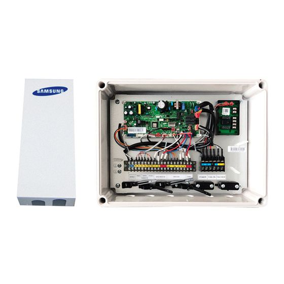
EXTERNAL APPEARANCE External Appearance EEV-KIT Parts and components EEV body (Coil wire : 2.5/5.0 HP = 2 m 7.5/10.0 HP = 7 m) Lower insulation Upper insulation Holder Cover Clamp EEV -Kit is not included in the Model "MXD-X000AN". Control-KIT Parts and components Controller board... -
Page 6: Accessories
ACCESSORIES Accessories Room/EVA IN EVA OUT EVA OUT sensor Disch. sensor EVA IN sensor holder ITEM sensor sensor holder Sensor clip (10 m) (OD Ø 6.8 mm) (10 m) (10 m) (OD Ø 7.8 mm) QUANTITY IMAGE ITEM Aluminum tape Rubber tape Insulator QUANTITY... -
Page 7: Before Installation
AHU-KIT doesn’t have the priority of control and operates according to the final signal. (SIMPLE BMS may indicate the different condition of AHU, if AHU was controlled by other controller finally.) Recommended AHU Size AHU Capacity ( ㎾ ) Heat Exchanger Volume ( ㎤ ) Model MXD-K025AN 1200 2000 MXD-K050AN 12.6 17.5... -
Page 8: Installation
INSTALLATION Control-KIT Installation • Make sure that Control-KIT should be installed within short distance from the EEV-KIT. - Supplied sensor in the Accessory box is 10 m. - 2.5/5.0HP EEV wire is 2 m - 7.5/10.0HP EEV wire is 7 m •... -
Page 9: Control-Kit Function
INSTALLATION (Continued) Control-KIT Function • Control-KIT uses EEV to control the amount of refrigerant flow and controls the system through outdoor unit and wired remote controller. • Control-KIT outputs the contact signal for AHU fan operation. Terminal block 1, 2 (Refer to page 10) outputs the AHU fan ON contact signal 220 - 240 V(208 - 230 V for US) for AHU when operating in Cool/Heat/Fan mode. -
Page 10: Control-Kit Circuit Diagram
INSTALLATION (Continued) Control-KIT Circuit Diagram AHU-KIT sensor has approximately 10㏀ of resistance value at indoor temperature of 25˚C. -
Page 11: External Controller Diagram
INSTALLATION (Continued) External Controller Diagram (MIM-B14) Circuit diagram of external Operation specification according to controller’s output AHU-KIT PBA Install option set up WIRE NO. Signal Install option AC LAMP 1, 2 Error check output 3, 4 Operation check output SEG 15 5, 6 ON/OFF input... -
Page 12: Setting The Temperature
INSTALLATION (Continued) Operational Voltage range against Setting temperature Room temperature setting Discharge temperature setting Set Temperature Set Temperature Set Temperature Simple BMS Simple BMS Simple BMS Voltage Range Voltage Range Voltage Range Heating Cooling Heating Cooling Heating Cooling 10.0 V ~ 9.6 V 30 ˚C 30 ˚C 10.00 V ~ 9.75 V... -
Page 13: Connecting The Power Terminal
INSTALLATION (Continued) Connecting the Power Terminal Connecting Power/Communication cable • Turn off the power before connecting the power terminal. • Maximum cable length and the amount of voltage drop for AHU power/communication cables should be under 10 %. • Consider power usage of the AHU when installing the ELB. •... -
Page 14: Control-Kit Connections
INSTALLATION (Continued) Control-KIT Connections POWER[AC] FAN ON[AC] FAN CHECK 1(L) 1(N) 1(L) 1(N) Fan status feedback (Non-voltage contact signal) 220 - 240 V(208 - 230 V for US), AHU fan ON contact signal 220 - 240 V(208 - 230 V for US), Power supply Outdoor unit Wired remote controller... -
Page 15: Eev-Kit Installation
INSTALLATION (Continued) EEV-KIT Installation • Make sure that EEV-KIT should be installed within 5m from the heat exchanger. (EEV -Kit is not included in the Model “MXD-X000AN”) 1) Open the EEV-KIT cover by unscrewing 4 screws on the side of the box. 2) Drill 4 holes on the correct position of the wall and fix the EEV-KIT securely. -
Page 16: Eva In/Out Sensor Installation
INSTALLATION (Continued) Sensor Installation These sensors are not included in the Model “MXD-X000AN”. • Please check sensor usage in label. EVA OUT DISCHARGE 1) EVA IN sensor should be attached after the distributor, on the coldest part of the heat exchanger pipe. 2) EVA OUT sensor should be installed approximately 200 mm behind the header of AHU heat exchanger. - Page 17 INSTALLATION (Continued) Sensor installation example 1 1) Check the sensor and the sensor holder. Sensor holder ID Type Sensor OD(mm) Sensor clip Sensor holder Note (mm) EVA IN sensor Ø 6 Ø 6.8 EVA OUT sensor Ø 7 Ø 7.8 Insulator Sensor 2) Braze the sensor holder on the selected location of the pipe.
- Page 18 INSTALLATION (Continued) Sensor installation example 2 1) Check the sensor and the sensor holder. Sensor Sensor holder ID Type Sensor OD (mm) Note (mm) Insulator Cable-tie EVA IN sensor Ø 6 Ø 6.8 EVA OUT sensor Ø 7 Ø 7.8 Aluminum tape Rubber tape 2) Put the sensor on the pipe.
-
Page 19: Function Setting
FUNCTION SETTING Setting an indoor unit address and installation option f Set the indoor unit address and installation option with remote controller option. Set the each option separately since you cannot set the ADDRESS setting and indoor unit installation setting option at the same time. You need to set twice when setting indoor unit address and installation option. - Page 20 FUNCTION SETTING (Continued) Option setting Status 1. Setting SEG2, SEG3 option Press Low Fan button( ) to enter SEG2 value. Press High Fan button( ) to enter SEG3 value. Each time you press the button, … will be selected in rotation. SEG2 SEG3 2.
- Page 21 FUNCTION SETTING (Continued) Option setting Status 1. Setting SEG16, SEG17 option Press Low Fan button( ) to enter SEG16 value. Press High Fan button( ) to enter SEG17 value. SEG16 SEG17 Each time you press the button, … will be selected in rotation. 2.
- Page 22 FUNCTION SETTING (Continued) Setting an indoor unit address (MAIN/RMC) 1. Check whether power is supplied or not. - When the indoor unit is not plugged in, there should be additional power supply in the indoor unit. 2. The reception part of a remote controller is built in the AHU KIT PBA. 3.
- Page 23 FUNCTION SETTING (Continued) Setting an indoor unit installation option (suitable for the condition of each installation location) 1. Check whether power is supplied or not. - When the indoor unit is not plugged in, there should be additional power supply in the indoor unit. 2.
- Page 24 FUNCTION SETTING (Continued) Option SEG7 SEG8 SEG9 SEG10 SEG11 SEG12 EEV Step when heating Explanation PAGE Use of hot water heater stops Remote Controller Display Indication Details Indication Details Indication Details Default Disuse value Indication and Details (*2) Noise decreasing setting (*2)
- Page 25 FUNCTION SETTING (Continued) 05 series installation option SEG1 SEG2 SEG3 SEG4 SEG5 SEG6 (When setting SEG3)Standard for Use of Auto Change Over (When setting SEG3)Standard (When setting SEG3)Standard for HR only in Auto mode heating temp. Offset cooling temp. Offset mode change Heating →...
- Page 26 FUNCTION SETTING (Continued) Temperature control Control variables when using hot water / Explanation by using simple BMS external heater Remote Controller Display Details Indication Details Indication Delay time Set temp. for heater On/Off for heater On At the same time as thermo on No delay At the same time as thermo on 10 minutes At the same time as thermo on 20 minutes Room...
-
Page 27: Changing A Particular Option
FUNCTION SETTING (Continued) SEG 3, 4, 5, 6, 8, 9 additional information When the SEG 3 is set as "1" and follow Auto Change Over for HR only operation, it will operate as follows. Standard temp. for Temp. → Heating Cooling Standard temp. -
Page 28: Troubleshooting
TROUBLESHOOTING Initial Check-up 1) Check the connection status between Indoor unit and the AHU-KIT. • Make sure you have followed instructions and wiring diagram shown in the installation manual. • Make sure AHU-KIT PBA is installed in a place where there are no influence from outdoor humidity, dust and temperature. -
Page 29: Sensor Error
TROUBLESHOOTING (Continued) Sensor Error AHU-KIT heat exchanger EVA IN sensor detachment error ↔ xxx (xxx : Address of an indoor unit with an error) Outdoor unit display Explanation Refer to below explanation. Reason Indoor heat exchanger EVA IN sensor detachment. 1) Explanation •... - Page 30 TROUBLESHOOTING (Continued) AHU-KIT temperature sensor OPEN/SHORT error (ROOM sensor OPEN/SHORT) (EVA IN sensor OPEN/SHORT) Outdoor unit display (EVA OUT sensor OPEN/SHORT) (Disch. sensor OPEN/SHORT) Explanation When OPEN/SHORT signal is received for temperature sensor of AHU-KIT Reason Poor connection between sensor and the PBA, or poor conditioned sensor. 1) Self check Is indoor room temperature sensor connector properly...
-
Page 31: Fan Error
TROUBLESHOOTING (Continued) Fan Error Outdoor unit display When Control-KIT outputs fan operation status signal and the fan feedback Explanation signal stays OPEN for more than 10 seconds. ( AHU-KIT only) • Poor AHU fan operation Reason • Missing or Incorrect circuit system for fan feedback check. 1) Self check Set the Install option 05 series SEG21 “0”. -
Page 32: How To Inspect Just In Case The Below Condition Is Satisfied
TROUBLESHOOTING (Continued) How to Inspect Just in Case the Below Condition is Satisfied Outdoor unit display In Cool mode, Min.100 and Max.480 EEV steps can be controlled. Explanation In Heat mode, Min 250 EEV steps can be controlled. • Inappropriate EVA IN/OUT sensor location •... -
Page 33: In-Tracking Error
TROUBLESHOOTING (Continued) In-tracking Error Error between AHU-KIT and outdoor unit at the beginning of operation(in tracking) Outdoor unit display Explanation Communication error between AHU-KIT and the outdoor unit Reason Refer to following self check 1) Self check Check the number of AHU-KIT set up on outdoor unit PBA is equal to actual number of AHU-KIT installed. - Page 34 TROUBLESHOOTING (Continued) Error between AHU-KIT and outdoor unit during operation(after tracking) Outdoor unit display Communication is off for 2 minutes between AHU-KIT and the outdoor unit during operation. Explanation (Ensure room) Reason Communication error between AHU-KIT and the outdoor or incorrect AHU-KIT number setting 1) Self check Press the reset KEY(K3) on the outdoor unit PBA and check the display.
-
Page 35: After Installation
AFTER INSTALLATION AHU-KIT Installation Check 1) Ensure that Control-KIT is correctly installed. • You can choose the built-in type or auxillary type depending on installation environment. • Ensure that the Control-KIT cables are correctly connected. • Control-KIT should be fireproofed and avoid direct sunlight upon installation. (Especially for individual type) •... -
Page 36: Test Operation
AFTER INSTALLATION (Continued) Test Operation 1) Before turning the power on, use DC 500V insulation tester to check the power terminal (L,N) and the earthing on AHU-KIT. • Resistance value should be over 30MΩ. 2) Test the voltage of power(L, N) before turning on the power. •... - Page 37 MEMO...
- Page 38 MEMO...
- Page 39 MEMO...