Table of Contents
Advertisement
Quick Links
Advertisement
Table of Contents

Related Manuals for Multitech MT-SMI-DK

Summary of Contents for Multitech MT-SMI-DK
- Page 1 Universal Socket MT-SMI-DK Developer Guide...
- Page 2 LEGAL NOTICES AND CONTACT INFORMATION Universal SocketModem Developer Guide S000342, Version V Use Rev S for all builds of the following devices. Consult model specific Device Guides for build options. If you have a older SocketModem, contact Multi-Tech for documentation. Cellular SocketModems MTSMC-G2 MTSMC-G3...
- Page 3 The Knowledge Base provides immediate access to support information and resolutions for all Multi-Tech products. Visit http://www.multitech.com/kb.go. Support Portal To create an account and submit a support case directly to our technical support team, visit: https://support.multitech.com Support Business Hours: M-F, 9am to 5pm CT...
-
Page 4: Table Of Contents
CONTENTS Contents Chapter 1 – Embedded Solutions ..........................7 Universal Socket Connectivity Features ..........................7 Universal IP ..................................7 Developer Documentation ..............................7 The Universal Socket Design ............................... 8 Embedded Modem and Device Servers ..........................9 Embedded Cellular Modems............................9 Embedded Analog Modems ............................9 Embedded Device Servers .............................. - Page 5 CONTENTS User Responsibility ................................ 33 Analog Telecom Safety Warnings ............................. 33 Chapter 6 – Labeling Requirements .......................... 34 Cellular Approvals and Labeling Requirements ........................ 34 Approvals and Certification ............................34 Analog Labeling Requirements ............................36 United States Labeling Requirements (for Dial-Up Modems) ..................36 Canadian Labeling Requirements (for Dial-Up Modems) .....................
- Page 6 CONTENTS HSPA / UMTS Antenna Requirements/Specifications ....................52 EV-DO and CDMA Antenna Requirements/Specifications ................... 53 GSM Antenna Requirements/Specifications ........................ 53 GPS Antenna Requirements/Specifications ........................53 Bluetooth Antenna Requirements/Specifications ......................53 Antennas Available from Multi-Tech ..........................54 Additional Sources of Bluetooth Antennas ........................55 Coaxial Cable Specifications ..............................
-
Page 7: Chapter 1 - Embedded Solutions
AT command interface. Universal IP provides developers a common programming interface effectively future proofing their application as new cellular technologies are introduced. Developer Documentation Download the documentation from www.multitech.com/support.go. Search on your model to access documentation for that device. ... -
Page 8: The Universal Socket Design
CHAPTER 1 – EMBEDDED SOLUTIONS The Universal Socket Design Each pin on a SocketModem corresponds to a particular function. The universal socket design provides a universal location for each pin. This allows each SocketModem to be used in a common board. Refer to Universal Socket Pinout for pinout details. -
Page 9: Embedded Modem And Device Servers
CHAPTER 1 – EMBEDDED SOLUTIONS Embedded Modem and Device Servers Embedded Cellular Modems Refer to Cellular SocketModems for details about specific models and related documentation. SocketModem iCell Complete, ready-to-integrate 2G and 3G, GSM and CDMA intelligent cellular modems using Multi-Tech's Universal Socket design and Universal IP stack for automatic/persistent connectivity and enhanced M2M (machine-to-machine) functionality. -
Page 10: Universal Developer Kit Contents
CHAPTER 1 – EMBEDDED SOLUTIONS Universal Developer Kit Contents Your Universal Developer Kit (MTSMI-UDK) includes the following: Developer Board One MTSMI-UDK Developer Board Power Supply One 100-240V 9V-1.7A power supply with removable blades One US blade/plug One EURO blade/plug One UK blade/plug Cables One RS-232 DB9F-DB25M serial cable One RJ-11 phone cable... - Page 11 CHAPTER 1 – EMBEDDED SOLUTIONS Latch Notch Sliding Lock Universal Socket Developer Guide...
-
Page 12: Chapter 2 - Universal Socket Pinout
CHAPTER 2 – UNIVERSAL SOCKET PINOUT Chapter 2 – Universal Socket Pinout Pinout Diagrams Universal SocketModem Pinout Note: Some modems do not include all the pins shown above. Refer to your model’s Device Guide for model specific pinout information. Signal Name In/Out Description Tip Signal from Telco. - Page 13 CHAPTER 2 – UNIVERSAL SOCKET PINOUT Signal Name In/Out Description Unused Reserved for future use. Unused Reserved for future use. Unused Reserved for future use. Unused Reserved for future use. Unused Reserved for future use. GPS-SDI GPS Data In. GPS-SDO GPS Data Out.
- Page 14 CHAPTER 2 – UNIVERSAL SOCKET PINOUT Signal Name In/Out Description –RXD Received Data. The SocketModem uses the RXD line to send data to the DTE and to send SocketModem responses to the DTE. In command mode, –RXD data presents the SocketModem responses to the DTE. SocketModem responses take priority over incoming data when the two signals are in competition for –RXD.
- Page 15 CHAPTER 2 – UNIVERSAL SOCKET PINOUT Signal Name In/Out Description –LED FDX LED Full Duplex (Active Low). LED Output. During normal operation, this pin lights the FDX LED to indicate a full duplex mode. –LED ACT LED Active (Active Low). LED Output. During normal operation, this pin lights the Activity LED when transmitting or receiving.
-
Page 16: Chapter 3 - Universal Design Considerations
CHAPTER 3 – UNIVERSAL DESIGN CONSIDERATIONS Chapter 3 – Universal Design Considerations Noise Suppression Design Considerations Adhere to engineering noise-suppression practices when designing a printed circuit board (PCB) containing the SocketModem. Noise suppression is essential to the proper operation and performance of the modem and surrounding equipment. -
Page 17: Electromagnetic Interference (Emi) Considerations
CHAPTER 3 – UNIVERSAL DESIGN CONSIDERATIONS Electromagnetic Interference (EMI) Considerations The following guidelines are offered specifically to help minimize EMI generation. Some of these guidelines are the same as, or similar to, the general guidelines. To minimize the contribution of the SocketModem-based design to EMI, you must understand the major sources of EMI and how to reduce them to acceptable levels. -
Page 18: Usb Design Considerations
Preheat zone 3: 175C Belt speed: 35.4 inches per minute Preheat zones have top and bottom heaters. WARNING: Do not wash. Washing may damage the device. NOTE: Conditions of Acceptability for UL are available upon request at https://support.multitech.com Universal Socket Developer Guide... -
Page 19: Chapter 4 - Developer Board And Schematics
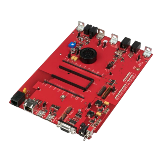
CHAPTER 4 – DEVELOPER BOARD AND SCHEMATICS Chapter 4 – Developer Board and Schematics Third-party components shown in the following drawings are included as examples only. Note: SocketModem Developer Board This developer board drawing shows the major board components for all SocketModems. Universal Socket Developer Guide... - Page 20 CHAPTER 4 – DEVELOPER BOARD AND SCHEMATICS Universal Socket Developer Guide...
-
Page 21: Socketmodem Developer Board Block Diagram
CHAPTER 4 – DEVELOPER BOARD AND SCHEMATICS SocketModem Developer Board Block Diagram Universal Socket Developer Guide... -
Page 22: Developer Board Schematics
CHAPTER 4 – DEVELOPER BOARD AND SCHEMATICS Developer Board Schematics Universal Socket Developer Guide... - Page 23 CHAPTER 4 – DEVELOPER BOARD AND SCHEMATICS Universal Socket Developer Guide...
- Page 24 CHAPTER 4 – DEVELOPER BOARD AND SCHEMATICS Universal Socket Developer Guide...
- Page 25 CHAPTER 4 – DEVELOPER BOARD AND SCHEMATICS Universal Socket Developer Guide...
- Page 26 CHAPTER 4 – DEVELOPER BOARD AND SCHEMATICS Universal Socket Developer Guide...
- Page 27 CHAPTER 4 – DEVELOPER BOARD AND SCHEMATICS Universal Socket Developer Guide...
- Page 28 CHAPTER 4 – DEVELOPER BOARD AND SCHEMATICS Universal Socket Developer Guide...
-
Page 29: Board Components
HAPTER 4 – DEVELOPER BOARD AND SCHEMATICS Board Components Schematic PCB Label or Description Jumper Label Location Next to Allows a stereo jack feed. Default is ON. If ON, then left and right stereo channels stereo jack. are combined and form a mono channel. J25&... -
Page 30: Installing A Universal Socket Communications Device Onto The Board
CHAPTER 4 – DEVELOPER BOARD AND SCHEMATICS Installing a Universal Socket Communications Device onto the Board To install a SMI/SMC modem: Align the pin of the universal socket communications device with pin 1 of the universal socket connector on the board and press firmly. Use the optional antenna lead to connect to the antenna connector on the modem. -
Page 31: Chapter 5 - Safety Notices And Warnings
CHAPTER 5 – SAFETY NOTICES AND WARNINGS Chapter 5 – Safety Notices and Warnings The following safety statements may be used in your product documentation. Cellular Safety RF Safety Due to the possibility of radio frequency (RF) interference, it is important that you follow any special regulations regarding the use of radio equipment. -
Page 32: Interference With Pacemakers And Other Medical Devices
CHAPTER 5 – SAFETY NOTICES AND WARNINGS non-respect de cette restriction peut entraîner la suspension ou le refus des services cellulaires au contrevenant, une action en justice, ou les deux. Éteignez votre appareil sans fil lorsque autour de l'essence ou pompes diesel-carburant et avant de remplir votre véhicule avec du carburant. -
Page 33: Device Maintenance
CHAPTER 5 – SAFETY NOTICES AND WARNINGS Device Maintenance Do not attempt to disassemble the device. There are no user serviceable parts inside. Do not expose your device to any extreme environment where the temperature or humidity is high. ... -
Page 34: Chapter 6 - Labeling Requirements
CHAPTER 6 – LABELING REQUIREMENTS Chapter 6 – Labeling Requirements Cellular Approvals and Labeling Requirements Note: For MTSMC LTE models, refer to the MTSMC-Lxx Device Guide for labeling requirements. Approvals and Certification The Multi-Tech SocketModem is an industry and/or carrier approved modem. In most cases, when integrated and used with an antenna system that was part of the Multi-Tech modem certification, additional approvals or certifications are not required for the device you develop as long as the following are met. - Page 35 CHAPTER 6 – LABELING REQUIREMENTS Universal Socket Developer Guide...
-
Page 36: Analog Labeling Requirements
CHAPTER 6 – LABELING REQUIREMENTS Example CDMA C1 SocketModem Label Notes: The label is shown larger than actual size. Actual labels will vary depending on the regulatory approval markings and content. Multi-Tech Model Identification Multi-Tech Ordering Part Number MEID (On EV2 Devices, the ESN is here.) Analog Labeling Requirements United States Labeling Requirements (for Dial-Up Modems) Telecom requirements apply to analog products only. -
Page 37: Canadian Labeling Requirements (For Dial-Up Modems)
CHAPTER 6 – LABELING REQUIREMENTS ## is the Ringer Equivalence Number without a decimal point (e.g. REN of 1.0 = 10, REN of 0.3 = 03). In the case of a “Z” ringer, ZZ shall appear. In the case of approved equipment without a network interface and equipment not connecting to circuits with analog ringing supplied then “NA”... - Page 38 CHAPTER 6 – LABELING REQUIREMENTS For terminal equipment intended for connection to loop-start or ground-start interfaces, the Ringer Equivalence Number (REN) must be calculated as per Section 1.8 of CS-03, Part I. A REN higher than that determined may be assigned by manufacturers to allow for production variations.
- Page 39 CHAPTER 6 – LABELING REQUIREMENTS For a new model that is registered to a family of previously certified TE, the self-marking format shall be: IC: XXXXXX-ZZZZZZZZ Where: “XXXXXX” is the Company Number, as in (d) above; and “ZZZZZZZZ” is either the old certification number minus the old company number, or a new Unique Product Number assigned by the applicant.
-
Page 40: Chinese Labeling Requirement
CHAPTER 6 – LABELING REQUIREMENTS Chinese Labeling Requirement For the MT5692SMI SocketModem, the following graphics need to appear on any product in China. Universal Socket Developer Guide... -
Page 41: Chapter 7 - Regulatory Information
After the initial release, products may be tested and certified for other countries or regions. For a current list of SocketModem approvals, check the Multi-Tech Systems www.multitech.com/global/approvals.go or contact Multi-Tech at oemsales@multitech.com. Notes: Some countries or regions have special import rules that require us assist customers with additional applications. Contact Multi-Tech at oemsales@multitech.com... -
Page 42: International Modem Restrictions
CHAPTER 7 – REGULATORY COMPLIANCE STATEMENTS International Modem Restrictions Some dialing and answering defaults and restrictions may vary for international modems. Changing settings may cause a modem to become non-compliant with national regulatory requirements in specific countries. Also note that some software packages may have features or lack restrictions that may cause the modem to become non- compliant. -
Page 43: 47 Cfr Part 68 Telecom
CHAPTER 7 – REGULATORY COMPLIANCE STATEMENTS 47 CFR Part 68 Telecom This equipment complies with Part 68 of the 47 CFR rules and the requirements adopted by the ACTA. Located on this equipment is a label that contains, among other information, the registration number and Ringer Equivalence Number (REN) for this equipment or a product identifier in the format: For current products: US:AAAEQ##Txxxx. -
Page 44: South African Statement
CHAPTER 7 – REGULATORY COMPLIANCE STATEMENTS Modular Jack (USOC): RJ11C or RJ11W (single line) Service Center in USA: Multi-Tech Systems, Inc. 2205 Woodale Drive Mounds View, MN 55112 USA (763) 785-3500 (763) 785-9874 Fax South African Statement This modem must be used in conjunction with an approved surge protection device. Thailand Approval for MT9234SMI and MT5692SMI This telecom device conforms to NTC requirements. -
Page 45: Brazil Approval For The Mt9234Smi
CHAPTER 7 – REGULATORY COMPLIANCE STATEMENTS For repeat calls to the same number: There shall be no more than 10 call attempts to the same number within any 30 minute period for any single manual call initiation, and The equipment shall go on-hook for a period of not less than 30 seconds between the end of one attempt and the beginning of the next attempt. -
Page 46: Korea Class B Statement
CHAPTER 7 – REGULATORY COMPLIANCE STATEMENTS Korea Class B Statement Equipment (Residential Use) 이 기기는 가정용(B급) 전자파적합기기로서 주로 가정에서 사용하는 것을 목적으로 하며, 모든 지역에서 사용할 수 있습니다. Japan Requirements These devices conform to (JATE) Japan Approval Institute for Telecommunications Equipment: MT5692SMI –... -
Page 47: Waste Electrical And Electronic Equipment Statement
CHAPTER 7 – REGULATORY COMPLIANCE STATEMENTS Waste Electrical and Electronic Equipment Statement This statement may be used in documentation for your final product applications. Note: WEEE Directive The WEEE Directive places an obligation on EU-based manufacturers, distributors, retailers, and importers to take- back electronics products at the end of their useful life. -
Page 48: Reach Statement
CHAPTER 7 – REGULATORY COMPLIANCE STATEMENTS REACH Statement Registration of Substances After careful review of the legislation and specifically the definition of an “article” as defined in EC Regulation 1907/2006, Title II, Chapter 1, Article 7.1(a)(b), it is our current view Multi-Tech Systems, Inc. products would be considered as “articles”. -
Page 49: Restriction Of The Use Of Hazardous Substances (Rohs)
CHAPTER 7 – REGULATORY COMPLIANCE STATEMENTS Restriction of the Use of Hazardous Substances (RoHS) Multi-Tech Systems, Inc. Certificate of Compliance 2011/65/EU Multi-Tech Systems confirms that its embedded products comply with the chemical concentration limitations set forth in the directive 2011/65/EU of the European Parliament (Restriction of the use of certain Hazardous Substances in electrical and electronic equipment - RoHS) These Multi-Tech products do not contain the following banned chemicals ... -
Page 50: Information On Hs/Ts Substances According To Chinese Standards
CHAPTER 7 – REGULATORY COMPLIANCE STATEMENTS Information on HS/TS Substances According to Chinese Standards In accordance with China’s Administrative Measures on the Control of Pollution Caused by Electronic Information Products (EIP) # 39, also known as China RoHS, the following information is provided regarding the names and concentration levels of Toxic Substances (TS) or Hazardous Substances (HS) which may be contained in Multi-Tech Systems Inc. -
Page 51: Information On Hs/Ts Substances According To Chinese Standards (In Chinese)
CHAPTER 7 – REGULATORY COMPLIANCE STATEMENTS Information on HS/TS Substances According to Chinese Standards (in Chinese) 依照中国标准的有毒有害物质信息 根据中华人民共和国信息产业部 (MII) 制定的电子信息产品 (EIP) 标准-中华人民共和国《电子信息产品污 染控制管理办法》(第 39 号),也称作中国 RoHS,下表列出了 Multi-Tech Systems, Inc. 产品中可能含有的 有毒物质 (TS) 或有害物质 (HS) 的名称及含量水平方面的信息。 有害/有毒物质/元素 成分名称 铅 汞 镉 六价铬... -
Page 52: Chapter 8 - Antennas, Cables, And Gps
CHAPTER 8 – ANTENNAS, CABLES, AND GPS Chapter 8 – Antennas, Cables, and GPS Note: For MTSMC LTE models, refer to the MTSMC-Lxx Device Guide for antenna information. Antenna System for Cellular Devices Cellular/wireless performance depends completely on implementation and antenna design. Integrating the antenna system into the product is a critical part of the design process;... -
Page 53: Ev-Do And Cdma Antenna Requirements/Specifications
CHAPTER 8 – ANTENNAS, CABLES, AND GPS EV-DO and CDMA Antenna Requirements/Specifications Category Description Frequency Range 824 – 894 MHz / 1850 – 1990 MHz Impedance 50 Ohms VSWR VSWR should not exceed 2.0:1 at any point across the bands of operation Typical Radiated Gain 2 dBi on azimuth plane Radiation... -
Page 54: Antennas Available From Multi-Tech
CHAPTER 8 – ANTENNAS, CABLES, AND GPS Antennas Available from Multi-Tech Part Number Description Quantity Quad Band ANQB-1HRA Hinged Right Angle 800/900/1800/1900 MHz Cellular Antenna, 7.5" ANQB-10HRA Hinged Right Angle 800/900/1800/1900 MHz Cellular Antenna, 7.5" ANQB-50HRA Hinged Right Angle 800/900/1800/1900 MHz Cellular Antenna, 7.5" Penta Band ANPB-1HRA Hinged Right Angle Penta Band Antenna... -
Page 55: Additional Sources Of Bluetooth Antennas
CHAPTER 8 – ANTENNAS, CABLES, AND GPS Additional Sources of Bluetooth Antennas Bluetooth antennas can be ordered from the following manufacturers. For the manufacturers listed without specific part numbers, be sure to select the antenna that meets the requirements/specifications. www.nearson.com (part number: S131AH-2450S) ... -
Page 56: Sma-To-Mmcx Connector
CHAPTER 8 – ANTENNAS, CABLES, AND GPS The SMA-to-MMCX cable is included in the Developer Kit for use with SocketModem EDGE (MTSMC-E1). The RSMA-to-MMCX cable is included in the Developer Kit for use with SocketWireless Bluetooth (MTS2BTSMI). Coax Cable Specifications Cable Type Coaxial Cable Attenuation... -
Page 57: Oem Integration
CHAPTER 8 – ANTENNAS, CABLES, AND GPS OEM Integration Follow the FCC notes in this document and product specific FCC grants and limitations in the Device Guide. Otherwise, further testing and device approvals may be necessary. FCC Notes The antenna gain, including cable loss, for the device you are incorporating into your product design must not exceed the requirements at 850 MHz and 1900 MHz as specified by the FCC grant for mobile operations and fixed mounted operations as defined in FCC CFR Title 47 Part 2.1091 and FCC CFR Title 47 Part 1.1307 of the FCC rules for satisfying RF exposure compliance. -
Page 58: Host Labeling
CHAPTER 8 – ANTENNAS, CABLES, AND GPS When one of the following test exclusion conditions is satisfied for all combinations of simultaneous transmission configurations, further equipment approval is not required to incorporate transmitter modules in host devices that operate in the mixed mobile and portable host platform exposure conditions. The grantee is responsible for documenting this according to Class I permissive change requirements. -
Page 59: Using Antenna Diversity
CHAPTER 8 – ANTENNAS, CABLES, AND GPS Antenna diversity provides an advantage in complex environments because if one receive antenna has a poor signal due to an interference null pattern, the other antenna is likely not in the null and will have better reception. The radio compares the reception from both receive antennas and uses the one with the strongest signal. -
Page 60: Global Positioning System (Gps)
CHAPTER 8 – ANTENNAS, CABLES, AND GPS Global Positioning System (GPS) This information applies only to the SocketModem models with the GPS option. Technical Specifications Category Description Receiver Type L1 Frequency GPS C/A code SBAS Capable 51 Channel Acquisitions 14 Channel Tracking Accuracy Position 2.5m CEP Velocity 0.1m/sec... - Page 61 CHAPTER 8 – ANTENNAS, CABLES, AND GPS Underwriters Laboratories requis Global Positioning System (GPS) Déclaration Underwriters Laboratories Inc. (UL) n'a pas testé la performance ou la fiabilité du matériel du système mondial de localisation (GPS), du logiciel d’exploitation du GPS, ou d'autres aspects liés au GPS de ce produit. UL a uniquement réalisé...
-
Page 62: Chapter 9 - Upgrading Modem Firmware
For most modems, it can be updated when new features are added. Check the multitech.com/support.go page to determine if there is an upgrade for your model. Updating radio code takes special tools and certification; contact Multi-Tech if you have questions. -
Page 63: Chapter 10 - Cellular Socketmodems
Each service provider has its own process for adding devices to their network. To find activation steps for your device: Go to http://www.multitech.com/support. Select your device. Scroll to Activation and click Download. -
Page 64: Chapter 11 - Analog Socketmodems
CHAPTER 11 – ANALOG SOCKETMODEMS Chapter 11 – Analog SocketModems Models and Documentation Note that build options for each device are included in the model’s Device Guide. Modem Models Device Guide AT Command Guide Other Guides SocketModem MT9234SMI S000534 S000434 S000262 Class 1 Fax Commands S000239 Class 2 Fax Commands SocketModem MT5692SMI... -
Page 65: Telecom
CHAPTER 11 – ANALOG SOCKETMODEMS Manufacturer Part Number Littlefuse P4202SCLRP ST Microelectronics SMP100MC-400 Recommended Poly Switch Thermal Fuse (SMT) RayChem / Tyco Electronics TS600-170F Recommended Poly Switch Thermal Fuse (Thru-Hole) Meritek MPTH600V150M-MT RayChem / Tyco Electronics TRF600-150 The Fuse & Sidactor are required in order to comply with UL60950 for protection against over-voltages Note: from power line cross. -
Page 66: Chapter 12 - Embedded Device Servers
CHAPTER 12 – EMBEDDED DEVICE SERVERS Chapter 12 – Embedded Device Servers Models and Documentation Note that build options for each device are included in the model’s Device Guide. Modem Models Device Guide AT Command Guide SocketEthernet IP MT100SEM-IP S000537 S000457 Universal IP Commands SocketWireless Bluetooth MTS2BTSMI... -
Page 67: Index
INDEX Index EMI ................17 activation ..............62 analog modem types ............9 FCC ................41 antennas................ 53 definitions ..............57 Bluetooth ..............54 notes ................. 56 approvals ............... 40 firmware ............... 61 Flash Wizard ..............61 Bluetooth Antenna Specifications ........ 52 Brazil Regulatory Statement ......... - Page 68 INDEX model identification ............34 safety notice Telecom ..............33 safety notices ..............31 soldering ............... 18 New Zealand Telecom Warning Notice ......43 South African Statement, Regulations......43 noise suppression ............16 stereo jack feed jumper ..........29 parts, recommended for analog ........63 Thailand Regulatory Statement ........