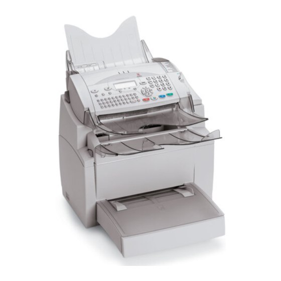
Xerox FaxCentre F116 Service Manual
Hide thumbs
Also See for FaxCentre F116:
- Specifications (2 pages) ,
- User manual (141 pages) ,
- Quick reference manual (2 pages)
Table of Contents
Advertisement
Quick Links
Advertisement
Chapters
Table of Contents
Troubleshooting

Related Manuals for Xerox FaxCentre F116


Summary of Contents for Xerox FaxCentre F116
- Page 1 FaxCentre F116/F116L SERVICE MANUAL 708P87887 9/04...
- Page 2 Xerox service documentation is intended for use by certified, product trained service per- sonnel only. Xerox does not warrant or represent that it will notify or provide to such customer any future change to this documentation. Customer performed service of equipment, or modules, components or parts of such equipment may affect whether Xerox is responsible to fix machine defects under the warranty offered by Xerox with respect to such equipment.
-
Page 3: Table Of Contents
Section Contents ........................2. Repair Analysis Procedures Section Contents ........................3. Image Quality Section Contents ........................4. Repairs/Adjustments Section Contents ........................5. Parts List Section Contents ........................6. General Procedures/Information Section Contents ........................7. Wiring Data Section Contents ........................FaxCentre F116/F116L 9/04... - Page 4 Introduction Page intentionally blank 9/04 FaxCentre F116/F116L...
-
Page 5: Introduction
Used to call the service technician attention to what is graphically represented inside the marking (including a warning). Used to prohibit the service technician from doing what is graphically represented inside the marking. Used to instruct the service technician to do what is graphically represented inside the marking. FaxCentre F116/F116L 9/04... -
Page 6: Warnings
• A part marked with the symbol shown on the left carries a high voltage. Touching it could result in an electric shock or burn. Be sure to unplug the power cord before servicing this part or the parts near it. 9/04 FaxCentre F116/F116L... - Page 7 • To promote safety, make sure that all tubing and other insulating materials are returned to their original positions. Make sure that floating components mounted on the circuit boards are at their correct distance and position off the boards. FaxCentre F116/F116L 9/04...
-
Page 8: Cautions
• Provide good ventilation at regular intervals if a service job must be done in a con- fined space for a long period of time. • Avoid dusty locations and places exposed to oil or steam. • Avoid working positions that may block the ventilation ports of the product. 9/04 FaxCentre F116/F116L... - Page 9 Precautions for storing the toner or drum cartridge. • Be sure to keep the toner or drum cartridge out of the reach of children. Licking the imaging cartridge or ingesting its contents is harmful to your health. FaxCentre F116/F116L 9/04...
- Page 10 Använd samma batterityp eller en ekvivalent typ som rekommenderas av apparattillverkaren. Kassera använt batteri enligt fabrikantens instruktion. Norway ADVARSEL Eksplosjonsfare ved feilaktig skifte av batteri. Benytt samme batteritype eller en tilsvarende type anbefalt av apparatfabrikanten. Brukte batterier kasseres i henhold til fabrikantens instruksjoner. viii 9/04 FaxCentre F116/F116L...
-
Page 11: Other Precautions
• Be sure to unplug the machine from the outlet before attempting to service the machine. • The basic rule is not to operate the machine anytime during disassembly. If it is absolutely necessary to run the machine with its covers removed, use care not to allow your clothing to FaxCentre F116/F116L 9/04... - Page 12 Handling of Other Parts • The magnetic roll in the toner cartridge generates a strong magnetic field. Do not bring it near a watch, floppy disk, magnetic card, or CRT tube. Handling of the Drum Cartridge During Transportation/Storage 9/04 FaxCentre F116/F116L...
- Page 13 • Use care not to contaminate the surface of the Drum with oil-base solvent, fingerprints, and other foreign matter. • Do not scratch the surface of the Drum. • Do not attempt to wipe clean the surface of the Drum. FaxCentre F116/F116L 9/04...
-
Page 14: Safety Information
• The ROS unit is NOT A FIELD SERVICE ITEM. Therefore, the ROS unit should not be opened under any circumstances. Laser Aperture of the ROS Unit This figure shows the view inside the Top Cover with the Toner Cartridge and the Drum Cartridge removed. Figure 1. 9/04 FaxCentre F116/F116L... - Page 15 770-795 nm Denmark ADVARSEL Usynlig laserstråling ved åbning, når sikkerhedsafbrydere er ude af funktion. Undgå udsættelse for stråling. Klasse 1 laser produkt der opfylder IEC60825 sikkerheds kravene. halvlederlaser Laserdiodens højeste styrke 5 mW bølgelængden 770-795 nm FaxCentre F116/F116L 9/04 xiii...
- Page 16 ADVERSEL Dersom apparatet brukes på annen måte enn spesifisert i denne bruksanvisning, kan bruk- eren utsettes för unsynlig laserstrålning, som overskrider grensen for laser klass 1. halvleder laser Maksimal effekt till laserdiode 5 mW bølgelengde 770-795 nm 9/04 FaxCentre F116/F116L...
- Page 17 • A laser safety label is attached to the outside of the machine as shown below. Laser safety label Figure 2. Laser Caution Label • A laser caution label is attached to the inside of the machine as shown below. Figure 3. FaxCentre F116/F116L 9/04...
-
Page 18: Precaution For Handling The Laser Equipment
• If the job requires that the machine be left ON, take off your watch and ring and wear laser protective goggles. • A highly reflective tool can be dangerous if it is brought into the laser beam path. Use utmost care when handling tools on the user’s premises. 9/04 FaxCentre F116/F116L... - Page 19 (equipment and materials) at customer locations. II. Scope Xerox Corporation and subsidiaries worldwide. III. Objective To enable prompt resolution of health and safety incidents involving Xerox products and to ensure Xerox regulatory compliance. IV. Definitions Incident: An event or condition occurring in a customer account that has resulted in injury, illness or prop- erty damage.
- Page 20 Fund all field retrofits. 2. Field Service Operations shall: a. Preserve the Xerox product involved and the scene of the incident inclusive of any associ- ated equipment located in the vicinity of the incident. b. Return any affected equipment/part(s) to the location designated by Xerox EH&S and/or the Business Division.
-
Page 21: Service Call Procedures
Service Call Procedures 1. Service Call Procedures SCP 1 Preventive Maintenance ................... SCP 2 Maintenance Schedule List..................FaxCentre F116/F116L 9/04... - Page 22 Service Call Procedures Page intentionally blank 9/04 FaxCentre F116/F116L...
- Page 23 Document transport rollers Document transport rollers Retard pad window Opening lever Figure 1. • Set the on/off switch to “O” (off). • Open the control panel/scanner by actuating the opening lever located on the left of the machine. FaxCentre F116/F116L 9/04...
- Page 24 • Wipe the scanner window with a lint-free cloth moistened with water, or with antistatic paper tissues as used for cleaning optical glass. Recommended interval: to be defined depending on utilization. After cleaning, is advised to make a local copy to check the cleanliness of the window. 9/04 FaxCentre F116/F116L...
- Page 25 SCP 2 Maintenance Schedule List. Error messages and corrective measures Refer to GP 21 Scanning and communication error codes and Repairs Analysis Procedures Repair Refer to Repairs and Adjustments. Disassembly/assembly worksheets Refer to REP 1 Disassembly Procedure Chart. FaxCentre F116/F116L 9/04...
- Page 26 *The Toner Cartridge and Drum Cartridge are customer replaceable units. Refer to Table 2. Table 2: Drum and toner cartridge part numbers Part name Part No. (110V) Part No. (240V) Drum cartridge (20K) 113R00655 113R00655 Toner cartridge (6K) 006R01218 106R00685 9/04 FaxCentre F116/F116L...
- Page 27 Malfunction of the Main Drive Motor..................Malfunction of the Fuser Temperature low/ Malfunction of the Fuser Warm up/ Malfunction of the Fuser Overheat ..................Malfunction of the Fuser Fan 6 Malfunction of the HVPS ...................... Malfunction of the Engine I/F....................FaxCentre F116/F116L 9/04...
-
Page 28: Repair Analysis Procedures
Repair Analysis Procedures Page intentionally blank 9/04 FaxCentre F116/F116L... -
Page 29: Troubleshooting For Paper Misfeeds Rap
PL 1 item dirty with paper dust? ↓ → Correct the Sensor Actuator movement. Does the Paper Feed Sensor Actua- → tor move correctly? Replace PS1, P/O PL 10 item Replace the Print Engine Board, PL 11 item 5. FaxCentre F116/F116L 9/04... -
Page 30: Paper Misfeed Occurred At The Paper Exit Section
Does the Paper Exit Roller rotate? Replace the Top Cover Assy, PL 7, item ↓ → Replace PS3, P/O PL 9 item Does the Paper Exit Sensor (PS3) → actuator move correctly? Replace the Print Engine Board, PL 11 item 5. 9/04 FaxCentre F116/F116L... -
Page 31: Troubleshooting For Malfunctions Rap
SOS Sensor malfunction Replace the Print Engine Board, PL 11 item 5. Malfunction of the Polygon Motor Cause Remedy Replace the ROS Unit, PL 11, item Polygon Motor malfunction Replace the Print Engine Board, PL 11 item 5. FaxCentre F116/F116L 9/04... -
Page 32: Malfunction Of The Main Drive Motor
Replace the Print Engine Board, PL 11 item 5. Malfunction of the H.V.P.S. Cause Remedy Replace the HVPS, PL 11, item 1 High voltage malfunction Replace the Print Engine Board, PL 11 item 5. 9/04 FaxCentre F116/F116L... -
Page 33: Malfunction Of The Engine I/F
Repair Analysis Procedures Malfunction of the Engine I/F FATAL Error Remedy Engine I/F Replace the Print Engine Board, PL 11 item 5. FaxCentre F116/F116L 9/04... - Page 34 Repair Analysis Procedures Page intentionally blank 9/04 FaxCentre F116/F116L...
- Page 35 Image Quality 3. Image Quality IQ 1 Image Quality Troubleshooting..................IQ 2 Image Quality Defects ....................FaxCentre F116/F116L 9/04...
- Page 36 Image Quality Page intentionally blank 9/04 FaxCentre F116/F116L...
- Page 37 94.2 mm Drum Cartridge Bias Transfer Roller (φ 16 mm) 50.3 mm Bias Transfer Roller, PL10, item Fuser Roll (φ 20 mm) 62.8 mm Fuser Assy, PL 9, item 1 Pressure Roll (φ 24 mm) 75.36 mm FaxCentre F116/F116L 9/04...
- Page 38 The paper may have absorbed some moisture due to high Replace the paper. humidity. Replace Bias Transfer Roller, PL10, item Replace the HVPS, PL 11, item Poor image transfer Replace the Print Engine Board, PL 11 item 5. 0951o220 9/04 FaxCentre F116/F116L...
- Page 39 Replace the Print Engine Board, PL 11 item 5. Foggy background Replace the HVPS, PL 11, item Poor development Replace the Print Engine Board, PL 11 item 5. Defective Drum Replace the Drum Cartridge. (end of life) 0951o218 FaxCentre F116/F116L 9/04...
- Page 40 Defective ROS unit Replace the Print Engine Board, PL 11 item 5. 0951o222 Offset image Replace the Fuser Assy, PL 9, Defective Fuser Roll item Replace the Bias Transfer Roller, Defective Bias Transfer Roller PL10, item 0951o219 9/04 FaxCentre F116/F116L...
- Page 41 REP 21 CIS Motor......................4-32 REP 22 Control Panel - Equipped Control Panel - Control Panel Flat Cable - Chassis..4-33 REP 23 Replacing the CPU Board..................4-35 REP 24 Replacing the Scanner (IIT) .................. 4-36 ADJ 1 Adjustments......................4-37 FaxCentre F116/F116L 9/04...
- Page 42 Repairs/Adjustments Page intentionally blank 9/04 FaxCentre F116/F116L...
-
Page 43: Repairs/Adjustments
Paper Feed Roll (REP 11) Top Cover, Rear Cover (REP 12) Fuser Assy (REP 13) (REP 14) LVPS (PU1) Main Drive Motor (M1) (REP 13) (REP 13) HVPS (HV1) Paper Feed Sensor (PS1) (REP 13) Fuser Fan (M2) FaxCentre F116/F116L 9/04... -
Page 44: Rep 2 Toner Cartridge, Drum Cartridge
1. Push the Top Cover Release Button and fully open the Top Cover. 2. Remove the Toner Cartridge. 3. Remove the Drum Cartridge. Drum Cartridge 4127s028a Toner Cartridge 4127s028b Main Paper Tray/Multi- purpose Tray 4127s101 Figure 1. 9/04 FaxCentre F116/F116L... -
Page 45: Rep 3 Replacing The Bias Transfer Roller (Btr)
2. Remove the bushings and gears from both ends of the Bias Transfer Roller and install them on the new Bias Transfer Roller. 3. Insert the Bias Transfer Roller in the Bias Transfer Roller Holder and swing the levers of the bushings up to the rear. 4127s032 4127s031 Figure 2. FaxCentre F116/F116L 9/04... -
Page 46: Rep 4 Removal Of The Retard Unit
Repairs/Adjustments REP 4 Removal of the Retard Unit Parts List on PL 8. 1. Place the machine with its backside down and remove the Paper Retard Unit (four screws). 4127s033 Figure 1. 9/04 FaxCentre F116/F116L... -
Page 47: Rep 5 Removal Of The Right Cover
5. Remove the Right Cover (two screws and tabs at three places). NOTE • When reinstalling the Right Cover, first align tabs (at three places) of the Right Cover into the frame of the machine. 4127s102 Figure 1. FaxCentre F116/F116L 9/04... -
Page 48: Rep 6 Removal Of The Left Cover
1. Remove the Left Cover (two screws and tabs at two places). NOTE • When reinstalling the Left Cover, first align tabs (at two places on the bottom) of the Left Cover into the frame of the machine. 4127s104 Figure 1. 9/04 FaxCentre F116/F116L... -
Page 49: Rep 7 Removal Of The Front Cover
5. Place the machine in the normal position and remove the Front Cover (tabs at four places). NOTE • When reinstalling the Front Cover, first align tabs (at two places on the bottom) of the Front Cover into the frame of the machine. 4127s039 Figure 2. FaxCentre F116/F116L 9/04... -
Page 50: Rep 8 Replacement Of The Paper Feed Roll
2. Place the machine with its backside down. 3. Unhook the spring and remove the right-hand side of the Paper Feed Roll shaft from its bush- ing. 4. Remove the Paper Feed Roll. 4127s040 Figure 1. 4-10 9/04 FaxCentre F116/F116L... -
Page 51: Rep 9 Removal Of The Ros Unit
3. Unplug the connectors (PJ5 and PJ9) from the Print Engine Board and remove the harness from the cord holder. 4. Remove the Toner Cartridge. 5. Remove the ROS Unit (six screws). Main Drive Motor 4127s105 Figure 1. FaxCentre F116/F116L 9/04 4-11... -
Page 52: Rep 10 Removal Of The Paper Empty Sensor (Pe1)
REP 10 Removal of the Paper Empty Sensor (PE1) Parts List on PL 8. 1. Remove the ROS Unit, 2. Remove the sensor fixing bracket and remove the Paper Empty Sensor (one connector). 4127s042 Figure 1. 4-12 9/04 FaxCentre F116/F116L... -
Page 53: Rep 11 Removal Of The Top Cover And Rear Cover
REP 11 Removal of the Top Cover and Rear Cover Parts List on PL 7 1. Remove the Right Cover, 2. Remove the Left Cover, 3. Remove the Top Cover and Rear Cover (six screws). 4127s043 Figure 1. FaxCentre F116/F116L 9/04 4-13... -
Page 54: Rep 12 Removal Of The Fuser Assembly
4. Remove the Fuser Assembly (three screws and three connectors). NOTE • The Fuser Assembly is to be replaced as a unit at about every 50,000 printed pages. 4127s044 Figure 1. *Replace as complete assembly only. 4-14 9/04 FaxCentre F116/F116L... -
Page 55: Rep 13 Removal Of The Lvps, Hvps And Paper Feed Sensor
4. Unplug the connectors (CN1 and CN3) from the LVPS and remove the harness from the cord holder. 4127s052 Figure 1. 5. Remove the LVPS (four screws). 6. Remove the HVPS (one screw). 7. Remove the Fuser Fan (two screws). Fuser Fan LVPS (PU1) HVPS (HV1) 4127s107 Figure 2. FaxCentre F116/F116L 9/04 4-15... - Page 56 Repairs/Adjustments 8. Remove the Paper Feed Sensor (one connector). 4121s078 4127s055 Figure 3. 4-16 9/04 FaxCentre F116/F116L...
-
Page 57: Rep 14 Removal Of The Main Drive Motor
Parts List on PL 10 1. Remove the LVPS, 2. Remove the gear plate (four screws). 3. Remove two gears. 4127s062 Figure 1. 4. Remove the left side plate (four screws and one connector). 4127s063 Figure 2. FaxCentre F116/F116L 9/04 4-17... - Page 58 Repairs/Adjustments 5. Remove the cartridge positioning plate (tabs at four places). 4127s064 Figure 3. 6. Remove the Main Drive Motor (four screws). 4127s065 Figure 4. 4-18 9/04 FaxCentre F116/F116L...
-
Page 59: Rep 15 White Roller
REP 15 White Roller Parts List on PL 3 Tools • None. Preliminary Steps • None. Disassembly • Stand at the back of the machine. Latch Opening limiter Stop White roller White roller end housings Figure 1. FaxCentre F116/F116L 9/04 4-19... - Page 60 • Press on the latch and place the other end of the white roller in end housing A. • Press on the latch and close the control panel, letting the stop lock behind the latch. 4-20 9/04 FaxCentre F116/F116L...
-
Page 61: Rep 16 Paper Separator
Retard pad Slide plate Figure 1. • Press the control panel opening lever. • Press outwards on the latch and release the stop. • Hold the retard pad assembly while removing the mounting screw. Remove the assembly. FaxCentre F116/F116L 9/04 4-21... - Page 62 Make sure the parts are oriented correctly. Insert the mounting screw, screw it in and tighten it. • Press on the latch (see 15) and close the control panel, letting the stop lock behind the latch. 4-22 9/04 FaxCentre F116/F116L...
-
Page 63: Rep 17 Control Panel, Circuit Board, Key Pad, Display, Glass, Top Cover
Control panel Figure 1. • Use a flat screwdriver as a lever at the four locations shown on the figure above to unclip and remove the top cover of the control panel, then close the chassis again. FaxCentre F116/F116L 9/04 4-23... - Page 64 Screw in and tighten the eight mounting screws. • Connect the connectors of the loudspeaker and of the display. • Connect the CIS flat cable to the connector on the control panel board. 4-24 9/04 FaxCentre F116/F116L...
- Page 65 • Position the lower part of the control panel on the chassis and clip it in place. Press down on the upper part of the control panel to complete the assembly. Mounting screws Control panel board Key pad Display Display window Equipped top cover Figure 3. FaxCentre F116/F116L 9/04 4-25...
-
Page 66: Rep 18 Rack - Cpu Board
• Push the slide lock towards the inside of the rack, pull out the rack, hold it and discon- nect the control panel and CIS flat cables, then remove the rack. • Completely remove the warranty label and clean its location with solvent. • Remove the four mounting screws and remove the CPU board. 4-26 9/04 FaxCentre F116/F116L... - Page 67 • Insert the rack into the rails up to the slide lock, reconnect the CIS motor and the printer cable. Completely push in the rack. • Screw in and tighten the two mounting screws. FaxCentre F116/F116L 9/04 4-27...
-
Page 68: Rep 19 Control Panel / Scanner Chassis - Printer
• Close the control panel and open the scanner chassis by means of its lever. Hold the scanner chassis/control panel, and use a flat screwdriver as a lever in the two notches indicated by the arrows in the figure above to loosen the mounting clips and remove the scanner chassis/control panel. 4-28 9/04 FaxCentre F116/F116L... - Page 69 • Put the control panel chassis in place. Open the control panel by means of its lever. • Screw in and tighten the two mounting screws. Close the control panel. • Refer to REP 18 for the connection of the flat cables and the CIS motor supply. FaxCentre F116/F116L 9/04 4-29...
-
Page 70: Rep 20 Cis Support - Cis Flat Cable
• Remove the four mounting screws. Remove the CIS support while releasing the con- trol panel flat cable. Mounting screws Slot for the control panel flat cable Figure 1. • Disconnect the CIS flat cable and its connector. Remove the CIS flat cable. 4-30 9/04 FaxCentre F116/F116L... - Page 71 • Put the CIS support in place, screw in and tighten the four mounting screws. • Pass the control panel flat cable into its cable guide. Pass the control panel and CIS flat cables under the control panel unlocking shaft. FaxCentre F116/F116L 9/04 4-31...
-
Page 72: Rep 21 Cis Motor
• Unpack and visually inspect the new parts. • Mount the 44/18 pinion gear on the CIS motor. • Pass the wires in the wire guide. Connect the grounding lug in the original location. • Screw in and tighten the two mounting screws. 4-32 9/04 FaxCentre F116/F116L... -
Page 73: Rep 22 Control Panel - Equipped Control Panel - Control Panel Flat Cable - Chassis
Disconnect the control panel grounding wire and remove the chassis. Left joint Control panel Right joint Chassis Figure 1. • Free the control panel flat cable from the cable guide and remove it. FaxCentre F116/F116L 9/04 4-33... - Page 74 • Press on the latch and close the control panel, letting the stop lock behind the latch. 4-34 9/04 FaxCentre F116/F116L...
-
Page 75: Rep 23 Replacing The Cpu Board
It is essential that the EEPROM memory “stays” with the machine, because this memory contains: - the consumables counters, - the counters of the number of printed pages, - the remote readout counters, - the network option (kit LAN). FaxCentre F116/F116L 9/04 4-35... -
Page 76: Rep 24 Replacing The Scanner (Iit)
Assembly • Replace the scanner. • Restore directory and parameters from the EEPROM card (MENU * 9). • Perform a remote readout (if the function has been enabled). • Perform a scanner calibration (MENU 8 0). 4-36 9/04 FaxCentre F116/F116L... -
Page 77: Adj 1 Adjustments
In the case of a scanner problem, repeat the calibration procedure above. In the case of a printer problem (the result remains unsatisfactory after scanner calibration): • Print the logs to check the print engine component of the machine. • Check the consumable. FaxCentre F116/F116L 9/04 4-37... - Page 78 Repairs/Adjustments Page intentionally blank 4-38 9/04 FaxCentre F116/F116L...
- Page 79 PL 7 - Printer Rack (1)......................5-16 PL 8 - Printer Rack (2)......................5-18 PL 9 - Fusing Unit....................... 5-20 PL 10 - Drive/Transfer Unit ....................5-22 PL 11 - Electrical Components................... 5-24 PL 12 - Required Service Tools/Screws................5-26 FaxCentre F116/F116L 9/04...
-
Page 80: Parts List
Parts List Page intentionally blank 9/04 FaxCentre F116/F116L... -
Page 81: Using The Part List Tables
Note 2: An item may be illustrated in a figure without being listed in the corresponding part list: such an article cannot be replaced other than by replacing the subassembly of which it is part. • REFERENCE column : Xerox part number. • DESCRIPTION column: description of the item. • QTY column : quantity. -
Page 82: Pl 1 - F116 Assembly And Trays
Réceptacle de sortie imprimante 002N02323 Paper feed tray Bac papier imprimante 117N01660 AC Power cord Cordon d’alimentation secteur 117N01661 Telephone line cord Cordon ligne téléphonique 497N00174 EEPROM card (Directory card) 097N01440 2nd Paper Tray Module (Not shown in illustration) 9/04 FaxCentre F116/F116L... - Page 83 Parts List Figure 1 / Planche 1 FaxCentre F116/F116L 9/04...
-
Page 84: Pl 2 - Control Panel - Scanner Chassis Assembly And Printer
PL 2 - Control Panel - Scanner Chassis Assembly and Printer ITEM No. PART No. DESCRIPTION Not Spared Control panel/scanner chassis assembly, (REP Ensemble pupitre-châssis scanner Not Spared Mounting screws for printer / control panel - scanner Vis de fixation imprimante pupitre-scanner 9/04 FaxCentre F116/F116L... - Page 85 Parts List Figure 2 / Planche 2 FaxCentre F116/F116L 9/04...
-
Page 86: Pl 3 - Retard Pad And White Roller Assemblies
Retard pad assembly, (REP 16) Kit déliasseur 101N01369 Scanner chassis assembly, (REP 24) Ensemble châssis scanner 007N01275 37/29 pinion gear, (REP 15) Pignon 37/29 013N13815 Bearing, (REP 15) Palier 022N02089 White roller, (REP 15) Rouleau blanc 013N13816 Bearing Palier 9/04 FaxCentre F116/F116L... - Page 87 Parts List Figure 3 / Planche 3 FaxCentre F116/F116L 9/04...
-
Page 88: Pl 4 - Control Panel Assembly
Afficheur LCD 019N00808 Key pad, (REP 17) Elastomère 140N62928 Control panel board, (REP 17) Cartre pupitre Not Spared Mounting screws for control panel board Vis de fixation carte pupitre 152N11570 Control panel flat cable Nappe pupitre 5-10 9/04 FaxCentre F116/F116L... - Page 89 Parts List Figure 4 / Planche 4 FaxCentre F116/F116L 9/04 5-11...
-
Page 90: Pl 5 - Rack - Cpu Board Assembly
Tiroir Not Spared Mounting screws for CPU board Vis de fixation carte UC 537N00169 EEPROM EEPROM 140N62935 CPU board and Dual Line Board Assembly (F116L), REP 18 REP 23 Kit Carte UC + Carte Biligne (F116L) 5-12 9/04 FaxCentre F116/F116L... - Page 91 Parts List Figure 5 / Planche 5 FaxCentre F116/F116L 9/04 5-13...
-
Page 92: Pl 6 - Cis Support And Cis Motor Assemblies
CIS flat cable, (REP 20) Nappe CIS 007N01276 CIS motor, (REP 21) Motorisation 007N01277 44/18 pinion gear Pignon 44/18 Not Spared Mounting screws for CIS motor Vis de fixation motorisation 117N01663 Grounding wire Fil de masse 5-14 9/04 FaxCentre F116/F116L... - Page 93 Parts List Figure 6 / Planche 6 FaxCentre F116/F116L 9/04 5-15...
-
Page 94: Pl 7 - Printer Rack (1)
022N02090 Roller Rouleau 007N01272 Gear assy Engrenage 101N01373 Cover, (REP 6) Couvercle 015N00536 Regulating plate assy Plateau assemblé 002N02323 Paper tray assembly Kit bac papier assemblé (REP 7) 002N02322 Front cover assembly, Kit capot avant assemblé 5-16 9/04 FaxCentre F116/F116L... - Page 95 Parts List Figure 7 / Planche 7 FaxCentre F116/F116L 9/04 5-17...
-
Page 96: Pl 8 - Printer Rack (2)
Paper out sensor, (REP 10) Interrupteur photo 007N01278 Roller gear Pignon chargeur 038N00447 Separator guide assembly Kit guide déliasseur assemblé 009N01486 Pressure spring Ressort de pression 009N01481 Tension spring Ressort de tension 019N00803 Separator Pad Déliasseur 5-18 9/04 FaxCentre F116/F116L... - Page 97 Parts List Figure 8 / Planche 8 FaxCentre F116/F116L 9/04 5-19...
-
Page 98: Pl 9 - Fusing Unit
Parts List PL 9 - Fusing Unit ITEM No. PART No. DESCRIPTION 126N00231 Fuser assembly, (REP 12) Unité four 5-20 9/04 FaxCentre F116/F116L... - Page 99 Parts List Figure 9 / Planche 9 FaxCentre F116/F116L 9/04 5-21...
-
Page 100: Pl 10 - Drive/Transfer Unit
PART No. DESCRIPTION 038N00446 Guide assembly Guide assemblé 007N01274 Drive gear assembly Engrenage d’entraînement assemblé 038N00445 Transfer guide assembly Guide transfert assemblé 127N07332 Main drive motor, (REP 14) Moteur 022N02095 Transfer roller, (REP 3) Rouleau transfert 5-22 9/04 FaxCentre F116/F116L... - Page 101 Parts List Figure 10 / Planche 10 FaxCentre F116/F116L 9/04 5-23...
-
Page 102: Pl 11 - Electrical Components
ITEM No. PART No. DESCRIPTION 105N02040 HVPS, (REP 13) Transformateur haut voltage 127N07329 Fuser Fan, (REP 13) Ventilateur 105N02042 LVPS, (REP 13) Alimentation 500N00110 ROS assembly, (REP 9) Tête d’impression assemblé 140N62937 Print engine board PNB assemblé 5-24 9/04 FaxCentre F116/F116L... - Page 103 Parts List Figure 11 / Planche 11 FaxCentre F116/F116L 9/04 5-25...
-
Page 104: Pl 12 - Required Service Tools/Screws
Illust D x L (mm) Illust D x L (mm) 1305 Screw (with 3704 Tapping screw 1318 spring washer) 3727 9739 9646 3501 3504 3505 Tapping screw 3923 Tapping screw 3541 9735 9742 3544 5-26 9/04 FaxCentre F116/F116L... - Page 105 GP 18 General Information ....................6-55 GP 19 Component Location ....................6-57 GP 20 Timing Chart......................6-59 GP 21 Scanning and communication error codes.............. 6-60 GP 22 Paper Misfeed Detection..................6-64 GP 23 Malfunction Detection....................6-66 GP 24 Functioning......................6-68 FaxCentre F116/F116L 9/04...
- Page 106 General Procedures/Information Page intentionally blank 9/04 FaxCentre F116/F116L...
-
Page 107: Gp 1 Machine Specifications
Dimensions (width x depth x height, without trays) 15.30 x 18.10 x 15.35 inch 389 x 460 x 390 mm Weight 24.25 lbs - 11 kg Consumables Reference Paper (RP) Type Letter: 20 lbs/m - 75 g/m FaxCentre F116/F116L 9/04... - Page 108 Scan speed for color document: • 300 x 300 dpi 16 sec. Zoom in steps of 1 % 25 % to 400 % Contrast 7 levels Brightness 7 levels Margin adjustment in steps of 0.5 mm. 7 levels 9/04 FaxCentre F116/F116L...
- Page 109 • Maximum starter toner cartridge life (in A4/ 2,000 letter pages at 5% area coverage) Consumables management By smart card Weight of drum 0.66 lbs - 300 g Weight of toner cartridge 1.1 lbs - 500 g FaxCentre F116/F116L 9/04...
- Page 110 Internet access Type PSTN-V90 Maximum speed in bps (V90) 56,000 Modem error correction mode Data compression V42bis ISP subscriptions 1 to 6 only 1 active ISP access protocol • ISP access security PAP & CHAP-MD5C Internet protocol TCP/IP 9/04 FaxCentre F116/F116L...
- Page 111 Legal: 8.5 x 14 inch 216 x 356 mm A4: 8.3 x 11.75 inch 210 x 297 mm Maximum speed with resolution 300 x 200 (fast) 16.5 ppm Multicopy 1 to 99 Zoom 25 % to 400 % Zoom steps FaxCentre F116/F116L 9/04...
- Page 112 Furthermore, it is essential to initialize the change of consumables, by means of the smart card supplied with the product (refer to the User Guide). 9/04 FaxCentre F116/F116L...
-
Page 113: Gp 2 Machine Components
Document output tray Paper output tray Printer cover opening lever Printer engine Paper feed tray On/off switch Phone line 2 connector (F116L only) Rack - CPU board USB connector Phone line 1 connector LAN connector Power outlet Figure 1. FaxCentre F116/F116L 9/04... -
Page 114: General Description
• A smart card reader used to initialize the consumables. It can also be used to store user functions (directory and user parameter). When replacing all or part of the consumables, perform the installation procedure for the new con- sumable item(s) (refer to the User Guide). 6-10 9/04 FaxCentre F116/F116L... -
Page 115: Gp 3 Installation Requirements
General Procedures/Information GP 3 Installation requirements Machine dimensions Figure 1. Figure 1 shows the overall dimensions of the machine, optional accessories not included. FaxCentre F116/F116L 9/04 6-11... -
Page 116: Environmental Conditions
• Avoid locations where frequent vibrations occur. • Avoid locations where water or other products might be splashed on the machine. • The machine should not be installed directly on the floor. • Place the machine on a flat horizontal support. 6-12 9/04 FaxCentre F116/F116L... -
Page 117: Package Contents
(the types of connector may vary depending on the coun- try). • If the machine is equipped with a second telephone socket (depending on the model), plug one end of the telephone lead (1) into socket (B) of the machine and the other end FaxCentre F116/F116L 9/04 6-13... - Page 118 • Connect one end of the USB cable to the PC connector (D) located at the back of your machine. • Connect the other end of the USB cable to the USB port of your PC. 6-14 9/04 FaxCentre F116/F116L...
-
Page 119: Paper Supply
Using the left and right notches of the machine as a guide, carefully push in the tray until it stops (as shown in Figure 3). Figure 3. Put the tray cover in place. Installing an additional paper tray (option) Refer to the User Guide. Figure 4. FaxCentre F116/F116L 9/04 6-15... - Page 120 Install the tray by clipping the two lugs in the corresponding openings at the back of the machine. Figure 5. Document output tray Install the tray by clipping the two lugs in the corresponding openings at the front near the top of the machine. Figure 6. 6-16 9/04 FaxCentre F116/F116L...
-
Page 121: Installing The Consumables
Release the tray so that it resumes its initial shape. If necessary, push against the tray at its base and in the middle so that it clips into place behind notch (A). Figure 7. Installing the consumables Refer to the User Guide. FaxCentre F116/F116L 9/04 6-17... -
Page 122: Gp 4 Start-Up And Software Configuration
MENU * # The description of these parameters can be found below. They are modified in the same manner as all other parameters. Position of the bits on display: Bit 8 Bit 1 6-18 9/04 FaxCentre F116/F116L... - Page 123 Reserved SOS-SEUILREC: Reception threshold 1 Values: # 0 (-43 dB)1 (-47 dB) SOS - EPTV29: Use Echo Protect Tone with V29 Values: #0: (No) 1: (Yes) SOS - ECHO: Echo cancelling Values: #0: (No) 1: (Yes) FaxCentre F116/F116L 9/04 6-19...
- Page 124 Naming Value Reserved Reserved Reserved Reserved SOS-HP: Speacker line monitoring during fax comm. Values: # 0 (No)1 (Yes) Reserved Reserved Reserved Soft-switch 6: Line Adjustment Default Naming Value Reserved Reserved Reserved Reserved Reserved Reserved Reserved Reserved 6-20 9/04 FaxCentre F116/F116L...
- Page 125 Naming Value SOS-AFFVIT: Communication rate display Values: # 0 (No) the page number is displayed 1 (Yes) the comm. rate is displayed. SOS-BTYPNUM: Access to impulse/DTMF parameter Values: 0 (Yes) Reserved # 1 (No) Reserved Reserved FaxCentre F116/F116L 9/04 6-21...
- Page 126 Values: 0 (No) # 1 (Yes) SOS-PROMONET: Auto directory enrichment (Internet promotion) Values: 0 (No automatic enrichment of directory) #1 (automatic enrichment of directory enabled) SOS-VIDEMBOX: Delete first message in the mailbox Values: # 0 (No) 1 (Systematically delete first document) 6-22 9/04 FaxCentre F116/F116L...
- Page 127 Values: 0 (No compression) 1 (compression enabled) SOS-REPSMTP: Wait for 2 packets after HELO command in SMTP Values: # 0 (Normal, wait for single rely packet) 1 (Wait for a second packet if the first one is empty) Reserved Reserved Reserved Reserved FaxCentre F116/F116L 9/04 6-23...
- Page 128 Default Naming Value SOS-CODMEM: Stored document encoding type Values: 00 (RL encoding) 01 (MH encoding) 10 (MR encoding) #11 (MMR encoding) SOS-CODCOM: COM negotiated encoding type Values: 01 (MH encoding) 10 (MR encoding) #11 (MMR encoding) 6-24 9/04 FaxCentre F116/F116L...
- Page 129 Values: 0 (For each line with an error) # 1 (Only once, then destroy) Reserved Reserved Reserved SOS-GARBAGE-FLASH: Flash memory garbage collection method Values: 0 (garbage collection when application terminates) # 1 (garbage collection as background task) ATTENTION : taken into account only after reboot of the CPU FaxCentre F116/F116L 9/04 6-25...
- Page 130 SOS-DEBRIDAGE-JAUGE: Acceptation of EEPROM cards at any moment Values: # 0 (No) 1 (Yes) Return to 0 after removing the card Reserved SOS-POINT-FINAL-SEUL: Final DATA_SMTP point on its own in the TCP frame ("Peltex" problem) Values: # 0 (Disabled)1 (Enabled) Reserved 6-26 9/04 FaxCentre F116/F116L...
- Page 131 # 0: No 1: Yes ATTENTION: If the directory is exported to a machine which does not support this format, the machine (receiver) will loose its current directory, and won’t be able to restore the new one. FaxCentre F116/F116L 9/04 6-27...
- Page 132 06 = 60 + 6*30 ms = 240 ms ..0F = 60 + 15*30 ms = 510 ms Soft-switch 28: Miscellaneous Default Naming Value Reserved Reserved Disable the 1 second timer before the hanging up #0: Enabled 1: Disabled 6-28 9/04 FaxCentre F116/F116L...
- Page 133 Activation of the validated menu #0: Enabled 1: Disabled Force the V29 modulation for 9600 and 7200 rates #0: Enabled 1: Disabled Reserved Reserved Reserved Reserved Soft-switch 30: Miscellaneous Default Naming Value Reserved Reserved Reserved Reserved Reserved Reserved Reserved Reserved FaxCentre F116/F116L 9/04 6-29...
-
Page 134: Gp 5 Software Download
Also, verify that SOS1 bit number 8 (the first number) is 0. Refer to the top of the last page. • The machine is now ready for use. 6-30 9/04 FaxCentre F116/F116L... - Page 135 At the end of download, the machine reboots. - Check that the download was successful by typing the following sequence on the machine keyboard: !, *, V. The machine display shows the software version and the checksum. FaxCentre F116/F116L 9/04 6-31...
-
Page 136: Gp 6 Saving Data On Eeprom Card
- CIS/Scanner/printer settings - Management modes of the paper trays - Enabling of fax answering secure mode • Fax Communication Parameters - Type of STN network - Transmission mode - Transmission report printout mode - Fax transmission/reception rate 6-32 9/04 FaxCentre F116/F116L... - Page 137 - Fixed times for Internet access - Prohibited time period for periodic connection - Internet connection/transmission modes - Internet rerouting mode - LAN configuration mode (manual/automatic) - Internet provider connection/mail service/servers/authentication parameters des providers internet - LAN mail service/server/authentication parameters. FaxCentre F116/F116L 9/04 6-33...
-
Page 138: Gp 7 Packing And Transport Of The Machine
4 - Pack the document and paper trays in their original plastic bags and packing boxes. Pack the machine in its original plastic cover and place it in the original packing box together with the accessories (trays, documentation, etc.). 5 - Seal the packing box with adhesive tape. Figure 1. 6-34 9/04 FaxCentre F116/F116L... -
Page 139: Gp 8 Functions Of The Service Provider
• Erase all, including the e-mail addresses stored in the directory, except for the other data in the directory. Reset to default configuration (combination of functions 0, 2, 6, 8): MENU • Erase all documents in memory (documents to be transmitted, received documents and deposited documents): MENU FaxCentre F116/F116L 9/04 6-35... -
Page 140: Other Functions
• Save the directory and the parameters on an EEPROM card via the smart card reader: MENU • Restore directory and parameters from an EEPROM card via the smart card reader: MENU • Start feeder scanner calibration: MENU • Display main software version: MENU 6-36 9/04 FaxCentre F116/F116L... - Page 141 • Manually reboot the machine (with SOS 1 bit 8 set to 1): MENU • Display PCL/SG Script fonts checksum: MENU • Retransmission of faxes to print to rerouting mail: MENU • Activation of dump RAM server: MENU • Accept soft download via internet or Intranet: MENU FaxCentre F116/F116L 9/04 6-37...
-
Page 142: Gp 9 Mechanical/Electrical
Paper Exit Roller. After this, the paper is fed out onto the Paper Output Tray Face-down Exit Laser Exposure Fusing ROS Unit Drum Charge PC Drum Development Manual Feed Tray Image Transfer Main Paper Tray/Multi- Paper Take-up Paper Take-up 4127s020 Second Paper Cassette Unit (option) Figure 1. 6-38 9/04 FaxCentre F116/F116L... - Page 143 Depressing Sensor (PS1) Paper Empty Sensor (PE1) Paper Tray 4127s021 Paper Feed Solenoid (SL1) Paper Feed Gear Clutch Figure 1. When SL1 is de-energized When SL1 is energized Depressing Cam Paper Tray 4127s022 4127s023 Figure 2. FaxCentre F116/F116L 9/04 6-39...
- Page 144 Second Paper Cassette Unit. When there is paper, the actuator is raised and thus the sensor light is blocked. When paper runs out, the actuator drops into a cutout in the Paper Lifting Plate, thus unblocking the sensor light. 6-40 9/04 FaxCentre F116/F116L...
-
Page 145: Gp 11 Drum Charge
• The electric potential on the surface of the charged Drum is approximately-800 V. Drum Cartridge Laser Exposure Cleaning blade Dev Mag Roll Pre-charge Film Bias Transfer Roller Drum 4121s030 Drum Cover 1. BCR 2. Drum 3. Ground 4. BCR voltage 4110s031 Figure 1. FaxCentre F116/F116L 9/04 6-41... -
Page 146: Gp 12 Laser Exposure
• The controller determines the start point of printing according to the TOD signal (sub-scanning direction) sent from the engine (Print Engine Board) and the HSYNC signal. • Laser exposure is started when the print head receives the VIDEO signal. 6-42 9/04 FaxCentre F116/F116L... - Page 147 General Procedures/Information /HSYNC /VIDEO 0.15 in (4 mm) Print Area 0.15 in 4 mm Figure 2. FaxCentre F116/F116L 9/04 6-43...
-
Page 148: Gp 13 Development
General Procedures/Information GP 13 Development Overview Toner is applied to the invisible static image on the Drum and a toner image (developed image) is created on the drum surface Toner Cartridge 4121s032 4121s031 4110s034 0992s24 Figure 1. 6-44 9/04 FaxCentre F116/F116L... - Page 149 Drum, from the Resin Sleeve and returns it back to the sump. Developing Blade DC-550V (DC-700 V max.) Voltage terminal (VBL) Developing Voltage ter- DC-300V (DC-400 V max.) minal (VB) Developing Lower Seal DC-300V (DC-400 V max.) Voltage terminal (VSS) FaxCentre F116/F116L 9/04 6-45...
-
Page 150: Gp 14 Image Transfer
• When cleaning the BTR and before printing, reverse bias is applied. • The residual electric potential on the paper is dissipated via a discharge needle. PC Drum Paper 4121s034 Paper Discharge Needle Drum Image Transfer Bias Reverse Bias 4127s026 Figure 1. 6-46 9/04 FaxCentre F116/F116L... -
Page 151: Gp 15 Fusing
(if the surface temperature of the Fuser Roll exceeds 230°C), the signal from IC1-79 changes from L to H to turn OFF the Fuser Lamp. PWB-A CMPIN/AN8/P63 DC5V +24V HEAT_N N.C. FUSER_LAMP HEAT_L CMPOUT DC5V H1: ON H1: OFF 4121s037 Figure 2. FaxCentre F116/F116L 9/04 6-47... - Page 152 ° ° The temperature is controlled to maintain at about 155 C during printing and at about 125 C dur- ing standby. This mode is maintained unless an error occurs or the Top Cover is opened. 6-48 9/04 FaxCentre F116/F116L...
- Page 153 The state before tempera- 50°C or more, less than 125 less than 50°C 125°C or more °C ture control is stopped Mode 1, Mode 1 warming-up Mode 2, 3 or Power OFF Mode 1 Mode 2 Mode 3 FaxCentre F116/F116L 9/04 6-49...
-
Page 154: Gp 16 Precautions For Disassembly
• When removing a board from its conductive bag or case, do not touch the pins of the ICs or the printed pattern. Place it in position by holding only the edges of the board. • Before plugging connectors into the board, make sure that the power cord has been unplugged from the power outlet. 6-50 9/04 FaxCentre F116/F116L... - Page 155 Drum to direct sunlight for long periods of time. • Use care not to contaminate the surface of the Drum with oil-base solvent, fingerprints, and other foreign matter. • Do not scratch the surface of the Drum. FaxCentre F116/F116L 9/04 6-51...
-
Page 156: Gp 17 Specifications
Within 21 sec. (when the rated voltage is supplied at Warm-up Time ° Recovery time from power saver mode: within 8 sec. ° (when the rated voltage is supplied at 23 System Speed 94.886 mm/sec (3.74 in/sec) 47.443 mm/sec (1.87 in/sec) (during half-speed control) 6-52 9/04 FaxCentre F116/F116L... - Page 157 850 W or less (220-240 V area) Continuation printing (average): 370 W or less Standby (fuser off): 15 W or less Standby (fuser on): 75 W or less (average) Standby (sleep): 15 W or less Acoustic noise Printing: 67 dB or less FaxCentre F116/F116L 9/04 6-53...
- Page 158 (DC24V, DC5V) Drive Source supply from main unit Width: 15.0 in (382 mm) Depth: 12.0 in (305 mm) Dimensions Height: 5.3 in (135 mm) (without Paper Cassette) approx. 4 lbs (1.8 kg) Weight *without Paper Cassette 6-54 9/04 FaxCentre F116/F116L...
-
Page 159: Gp 18 General Information
The following items should be checked periodically: • Make sure the power cord does not feel warm. • The power cord should be free of cracks and scratches. • The power cord should be firmly plugged into the power outlet. FaxCentre F116/F116L 9/04 6-55... - Page 160 General Procedures/Information Parts Identification 4127s006a Figure 1. Face-down Tray Manual Feed Tray Main Paper Tray/Multi-purpose Tray Second Paper Cassette (Option) Second Paper Cassette Unit (Option) Power Switch Top Cover Release Button Drum Cartridge Toner Cartridge 6-56 9/04 FaxCentre F116/F116L...
-
Page 161: Gp 19 Component Location
20 Paper guides for manual feed tray Drum 21 Paper Empty Sensor (PE1) 10 Bias Transfer Roll 22 ROS Unit Paper Feed Sensor 23 Document Output Tray (PS1) Second Paper Tray * 12, 14, 15, 16, and 17: Options Module * FaxCentre F116/F116L 9/04 6-57... - Page 162 Toner Transport Roller Paper Exit Roller (Face-down) 10 Paper Feed Roller Fuser Roller 11 Drive Transmission Gear Second Paper Cassette Module Bias Transfer Roll Section (option) 13 2nd Paper Feed Roller Drum 14 Main Drive Motor (M1) 6-58 9/04 FaxCentre F116/F116L...
-
Page 163: Gp 20 Timing Chart
Drum Charge (output) Exposure (output) Development (output) Image Transfer 4127s070 (output) Figure 1. Print Ending Paper Exit Sensor (PS3) Polygon Motor (M5) Main Drive Motor Exposure (output) Drum Charge (output) Development (output) Image Transfer (output) 4127s071 Figure 2. FaxCentre F116/F116L 9/04 6-59... -
Page 164: Gp 21 Scanning And Communication Error Codes
Code 0A - No document to recover You have attempted to recover a document from a sender, but the latter has not prepared (stored) the document or the password that was entered is wrong. 6-60 9/04 FaxCentre F116/F116L... - Page 165 You have requested the retransmission of a document by a machine that does not have a retransmit function. Code 19 - Stopped by sender Communication stopped by the sender (for example, a fax attempts to recover a document from your machine, while there is no document waiting for this sender). FaxCentre F116/F116L 9/04 6-61...
- Page 166 Disconnect of the POP3 server to receive mail. The service has become momentarily unavail- able: try to connect again later. Code 48 - Internet disconnect The service has become momentarily unavailable: try to connect again later. 6-62 9/04 FaxCentre F116/F116L...
- Page 167 To verify the Internet parameters, print them out by entering the key sequence MENU, 9, 4, 5 followed by the OK key. Code 50 - Server Error Verify the parameters SMS server number or a communication error occurred during data transfer. FaxCentre F116/F116L 9/04 6-63...
-
Page 168: Gp 22 Paper Misfeed Detection
6. The Paper Feed Sensor (PS1) is in the activated state when the Power Switch (S1) is turned ON or the cover is closed. 7. The Paper Exit Sensor (PS3) is in the activated state when the Power Switch (S1) is turned ON or the cover is closed. 6-64 9/04 FaxCentre F116/F116L... - Page 169 General Procedures/Information How to Reset a Paper Misfeed Close the Top Cover after the misfed sheet of paper has been cleared. FaxCentre F116/F116L 9/04 6-65...
-
Page 170: Gp 23 Malfunction Detection
C at 600 dpi and 110 C at 1200 dpi during printing, and 70 C during standby). Fuser Fan Malfunction The FAN_LOCK signal remains HIGH or LOW for a continuous 2-sec. period while the Fuser Fan (M2) is turning. 6-66 9/04 FaxCentre F116/F116L... - Page 171 1. The drum charge monitor voltage (C_MON) falls outside the specified range at any time 0.5 sec. after the power has been turned ON. 2. The image transfer monitor voltage (T_MON_V, T_MON_I) signal falls outside the specified range. FaxCentre F116/F116L 9/04 6-67...
-
Page 172: Gp 24 Functioning
Before performing any service on the CPU electronic circuit board, it is also preferable to: • Disconnect the phone line • Set the power switch to the OFF position. • Disconnect all external interconnect leads (LAN, ECP). • Disconnect the power cord. 6-68 9/04 FaxCentre F116/F116L... - Page 173 Wiring Data 7. Wiring Data Control Panel Board ......................Sensors ..........................CPU Board Information ......................Connector Locations ......................List of connectors ......................... Wiring Schematics......................7-12 Electrical Components Layout.................... 7-14 Electrical Parts Function..................... 7-16 Wiring Diagram........................7-19 FaxCentre F116/F116L 9/04...
- Page 174 Wiring Data Page intentionally blank 9/04 FaxCentre F116/F116L...
-
Page 175: Control Panel Board
• PSF: document present, detects the insertion of a document to be scanned. • DA: start of scan, used to position the document relative to the CIS. • OUV: cover open, detects the opening of the scanner cover: the motor is then stopped automatically. FaxCentre F116/F116L 9/04... - Page 176 Not used STSC* Start of scan sensor PSF* Sheet present sensor OUVCAP* Cover open sensor P3V3 3.3 V supply VALIM 5 V supply ALIMCOUPE 5 V supply Differential LF signal to loudspeaker Differential LF signal to loudspeaker 9/04 FaxCentre F116/F116L...
-
Page 177: Cpu Board Information
The code is loaded from this flash memory into SDRAM, and the microprocessor executes its instructions from the SDRAM. Before printing, the documents to be printed are stored as bitmaps in SDRAM. The SDRAM is also used as the working memory for the Digicolor2. FaxCentre F116/F116L 9/04... - Page 178 USB slave 16 bits SDRAM SDRAM Bus périphérique/ Peripheral bus Flash Carte à puce/Smart card ISO 7816 8 bits adapt Modem 16 bits Interface ligne/ Line Interface PSTN Connecteur interne/ Internal connector Connecteur externe/ External connector Figure 1. 9/04 FaxCentre F116/F116L...
-
Page 179: Connector Locations
Wiring Data Connector Locations Diagram of the connector locations (Not (STN) used) Moteur CIS (CIS motor) Imprimante (printer) Pupitre (control panel) Figure 1. FaxCentre F116/F116L 9/04... -
Page 180: List Of Connectors
TXIMP CPU command (serial data transmitted to printer) VSYNC Vertical sync (page) Engine status busy Controller status busy Ground Pull-up to 5 V Print* (not used) 5 V supply Ground 5 V supply P24V 24V supply 9/04 FaxCentre F116/F116L... - Page 181 ALIMCIS 5 V supply VREFCIS CIS reference voltage SPCIS CIS start pulse (line sync) CLKCIS CIS pixel clock (point sync) ALIMLED LED supply (current) GNDLEDB Blue LED cathode GNDLEDV Green LED cathode GNDLEDR Red LED cathode Ground FaxCentre F116/F116L 9/04...
- Page 182 Ground USB: USB interface Signal Input/Output VBUS_USB Supply from master USBN Differential pair USBP Differential pair Ground LAN: local area network interface Signal Input/Output Network transmission differential pair Network transmission differential pair Network reception differential pair 7-10 9/04 FaxCentre F116/F116L...
- Page 183 Signal Input/Output Not connected Not connected Network reception differential pair Not connected Not connected STN (“RTC”): switched telephone network interface Signal Input/Output Not connected Loopback L1 Telephone line pair Telephone line pair Loopback L2 Not connected FaxCentre F116/F116L 9/04 7-11...
-
Page 184: Wiring Schematics
Resistors R4044 and R4045 5 V regulator Z113 ANAVCC Vcc ana Z4376 3V regulator Resistors R4395 and R4397 ALIM CIS command + 5 V : VCC 3.3 V regulator + 3.3 V : P3V3 Z1020 Figure 1. 7-12 9/04 FaxCentre F116/F116L... - Page 185 29.4912 MHz Y550 25 MHz Y8800 Figure 2. Reset Low voltage detect modem reset (I/O) Modem MAX809 - T : 3.08 V 3.3 V Z210 DIGICOLOR2 /max809 reset Storage flash memory nPwr_rst LAN reset (I/O) Figure 3. FaxCentre F116/F116L 9/04 7-13...
-
Page 186: Electrical Components Layout
Electrical Components Layout Printer Engine 4127M004AA Figure 1. Main Drive Motor Interlock Switch Fuser Fan Paper Empty Sensor Fuser Lamp Paper Feed Sensor Thermistor Paper Exit Sensor Thermostat Paper Feed Solenoid ROS Unit LVPS Power Switch HVPS 7-14 9/04 FaxCentre F116/F116L... - Page 187 Second Paper Cassette Module (option) SL21 4127s014 Figure 2. Paper Empty Sensor PWB-A Connecting Board SL21 Paper Feed Solenoid Cassette Type Detecting SW21 Switch Print Engine Board Print engine board Figure 3. PWB-A Print Engine Board FaxCentre F116/F116L 9/04 7-15...
-
Page 188: Electrical Parts Function
PC Drum with the laser beam according to the image signals. Power Switch Turns ON or OFF the machine. Detects the opening or closing of the Top Interlock switch Cover. Cuts output voltage (except 5 VDC) when the Top Cover is open. 7-16 9/04 FaxCentre F116/F116L... - Page 189 Connecting Board from the machine to/from components in the Second Paper Cassette Module. * Displayed in the Status Monitor (within the printer status window box) of the PC. PU1 (LVPS) CN1(2P) CN3(2P) VR61 CN2(7P) 4127s016 Figure 1. FaxCentre F116/F116L 9/04 7-17...
- Page 190 Developing Voltage terminal (DC-400 V max)) Developing Lower Seal Voltage terminal (DC-400 V max) Developing Toner Blade Voltage terminal (DC-700 V max) Image Transfer terminal (DC4300 V max/ DC-600 V max.) VR51 For factory setting only [Do not touch] 7-18 9/04 FaxCentre F116/F116L...
-
Page 191: Wiring Diagram
Wiring Data Wiring Diagram Figure 1. FaxCentre F116/F116L 9/04 7-19... - Page 192 Wiring Data Page intentionally blank 7-20 9/04 FaxCentre F116/F116L...
- Page 193 Page 1 of 2 APPENDIX A: Health & Safety Incident Report Involving a Xerox Product Customer Identification Customer Name: Name of Customer Contact Person: Address: E-mail: Telephone : Fax : Customer Service Engineer Identification Name: Employee : Pager : Location:...
- Page 194 E-Mail: Mailing Address: Date Report Submitted: Instructions: E-mail or fax this completed form to EH&S: ž For incidents in Xerox Europe and Developing Markets East (Middle East, Africa, India, China, and Hong Kong) please e-mail: Elaine.Grange@gbr.xerox.com or fax: +44 (0) 1707 35 3914 [intelnet 8*668 3914] Note: - If you fax this form, please also send original by internal mail ž...
- Page 195 XEROX EUROPE PUBLICATION COMMENT SHEET Please copy this master sheet and use it to help us to improve this publication. We would like you to tell us about improvements to its accuracy, format and quality. Please give specific references, i.e.: page numbers and figure numbers and attach marked up photocopies wher- ever possible.
- Page 196 XEROX EUROPE...