
Related Manuals for Extron electronics MTP SW6


Summary of Contents for Extron electronics MTP SW6
- Page 1 User Manual Twisted Pair MTP SW6 Six Input MTP Twisted Pair Switcher 68-1462-01 Rev. B 02 10...
- Page 2 Safety Instructions • English Warning Power sources • This equipment should be operated only from the power source indicated on the product. This This symbol is intended to alert the user of important operating and mainte- equipment is intended to be used with a main power system with a grounded (neutral) conductor. The third nance (servicing) instructions in the literature provided with the equipment.
- Page 3 Operation of this equipment in a residential area is likely to cause harmful interference, in which case the user will be required to correct the interference at his own expense. Copyright © 2010 Extron Electronics. All rights reserved. Trademarks All trademarks mentioned in this manual are the properties of their respective owners.
-
Page 4: Table Of Contents
Remote Control ........About this Manual ........... 1 Simple Instruction Set ™ Control ...... 20 About the MTP SW6 Switcher ......1 Host-to-Interface Communications ..... 20 RS-232 Function .......... 2 Symbol Deinitions ........20 Twisted Pair (TP) Cable Advantages ....3 Unit-Initiated Messages ...... -
Page 5: Introduction
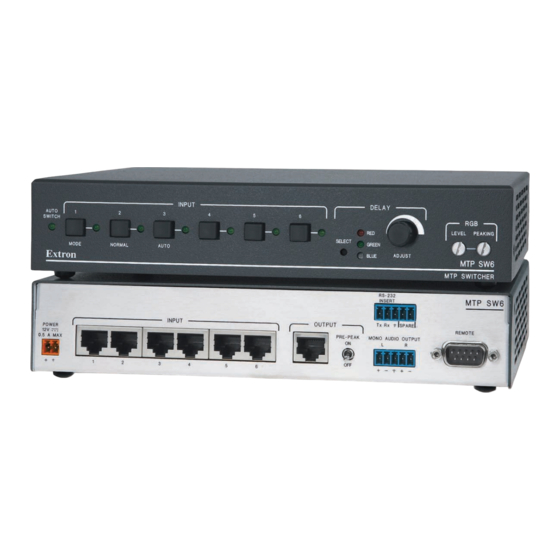
MTP SW6 twisted pair switcher. About the MTP SW6 Switcher The Extron MTP SW6 is a 6-input, 1-output twisted pair switcher that is compatible with the entire line of Extron MTP transmitters and receivers. The Extron MTP transmitters and receivers are a system for long-distance distribution of video and either audio or RS-232 communications. -
Page 6: Rs-232 Function
• Supports baud rates up to 38,400, data bits, parity, stop bits, and data format without coniguration. NOTE: Higher rates are possible, but performance will vary as a function of baud rate and TP cable length. MTP SW6 • Introduction... -
Page 7: Twisted Pair (Tp) Cable Advantages
Cables terminated on site should be tested before use to ensure that they comply with Category 5 speciications. • Resolutions marked with an asterisk in table 1 have the same range speciications at 75 Hz. MTP SW6 • Introduction... - Page 8 <250' (75 m) >300' (90 m) 300' (90 m) 250' (75 m) 400' (120 m) 400' (120 m) HDTV 1080p <250' (75 m) >300' (90 m) 300' (90 m) 250' (75 m) 400' (120 m) 400' (120 m) MTP SW6 • Introduction...
-
Page 9: Features
MTP transmitter into two channels for direct connection of audio equipment that is located within the same rack as the MTP SW6. Local audio output volume adjustment and muting — A local line level output has volume and muting control via RS-232 that can be set dynamically to feed an audio ampliier, eliminating the need for a preampliier in many systems. -
Page 10: Installation And Operation
• Optimizing the Video Mounting the MTP SW6 The MTP SW6 can be set on a table, mounted on a rack shelf, or mounted under a desk, podium, or tabletop. Tabletop Use Four self-adhesive rubber feet are included with the switcher. For tabletop use, attach one foot at each corner on the bottom of the unit and place the unit in the desired location. - Page 11 (such as the use of power strips). Rack shelf mounting instructions Remove feet from the bottom of the MTP SW6 if installed. Mount the switcher on the rack shelf, using two 4-40 x 3/16” screws in opposite (diagonal) corners to secure it to the shelf (figure 3).
-
Page 12: Furniture Mounting
For furniture mounting, do not attach the rubber feet. Furniture mount the switcher using the optional MBU 125 under desk mounting kit (part #70-077-01) as follows: Remove feet from the bottom of the MTP SW6 if installed. Attach the furniture mounting brackets to the switcher with the four machine screws supplied with the mounting kit (igure 5). -
Page 13: Connectors And Settings
• For best results, use a combined cable length of at least 50 feet (15 m) between the transmitter and the receiver on the MTP SW6 output. • RJ-45 termination with CAT 5, CAT 5e, or CAT 6 cable must comply with the TIA/EIA T568A or TIA/EIA T568B wiring standards for all connections. - Page 14 See the Input SIS Commands for details. selection MTP SW6 • Installation and Operation...
- Page 15 NOTE: The cable used to connect the Remote port to a computer, control, contact closure device, or IR control kit may need to be modiied by removing pins or cutting wires. If unneeded pins are connected, the switcher may hang up. See for additional information. Remote Control MTP SW6 • Installation and Operation...
-
Page 16: Making Connections
Rather than the included power supply, you can use an optional Extron PS 123 Universal 12 VDC Power Supply, part #60-814-01, can power multiple Extron 12 VDC devices using only one AC power connector. MTP SW6 • Installation and Operation... -
Page 17: Tp Cable Termination
• The green, brown, and blue wire pairs of this cable have virtually identical lengths and should be used to transmit the RGB signals. • The orange wire pair of this cable has a different length and should not be used to transmit the RGB signals. MTP SW6 • Installation and Operation... -
Page 18: Receiver Considerations
If a receiver is the last receiver in a daisy chain, its end unit DIP switch setting needs to be changed. Refer to the MTP 15HD RS Series User’s Manual that applies to your receiver or details. MTP SW6 • Installation and Operation... -
Page 19: Operation
Select button ( f ) for skew adjustment using the Adjust control ( h ). The LED for the selected color lashes when the skew compensation for that color’s video signal has reached the minimum or maximum limit. MTP SW6 • Installation and Operation... -
Page 20: Switch Mode
Press and hold the Mode (Input 1) button. Press and release the Normal (Input 2) button. The Auto Switch Active LED goes off. Release the Mode button. NOTE: When the switcher exits auto switch mode, it deselects all inputs (no output). MTP SW6 • Installation and Operation... -
Page 21: Optimizing The Video
MTP SW6 is > 300 feet, turn the transmitter’s Pre-Peak switch on. For shorter cables, turn the switch off. For the output — If the cable between the MTP SW6 and the receiver is > 300 feet, turn the switcher’s Pre-Peak switch on. For shorter cables, turn the switch off. -
Page 22: Skew Delay Compensation
10-second timeout to elapse. If one of the remaining colors is left shifted, repeat steps 3 and 4. Repeat step 1 through 5 for each input. MTP SW6 • Installation and Operation... -
Page 23: Remote Control
Remote Control This section discusses how to connect and conigure the MTP SW6. Topics that are covered, include: Simple Instruction Set Control • • Windows-Based Program Control Contact Closure Control • • IR 102 Infrared Remote Control The switcher can be remotely controlled via its rear panel Remote connector (Figure 13). -
Page 24: Simple Instruction Set Control
1 – 18 (1 dB/step) = Volume adjustment range 0 – 100 = Mute, Front panel lock 0 = off 1 = on = Switch mode 1 = normal (manual) 2 = auto = Firmware version v.vv MTP SW6 • Remote Control... -
Page 25: Unit-Initiated Messages
When a local event, such as a front panel operation, auto switch, or error condition, occurs, the unit responds by sending a message to the host. The unit-initiated messages are listed below: (c)COPYRIGHT 2008, EXTRON ELECTRONICS “MTP SW6”, v.vv The connected unit issues the appropriate copyright message (above) when it irst powers is the irmware version number. -
Page 26: Timeout
Symbols are used throughout the table to represent variables in the command/response ields. Command and response examples are shown throughout the table. The ASCII to HEX conversion table below is for use with the command/response table. ASCII to HEX Conversion Table Space MTP SW6 • Remote Control... -
Page 27: Command/Response Table For Sis Commands
Decrease level setting 1 step. -ILVL Ilvl Show level ILVL NOTE: = Input number = Threshold 0 = outside threshold 1 = within threshold = Input peaking range 00 - 65 = Input level range 000 - 255 MTP SW6 • Remote Control... - Page 28 1 = RS-232 = Video plane 0 = red 1 = green 2 = blue = RS-232 insert status 0= disabled 1 = enabled = Audio/RS-232 wire pair input type 0 = audio 1 = RS-232 MTP SW6 • Remote Control...
- Page 29 0 = outside threshold 1 = within threshold = Volume adjustment range 0 - 100 = Mute, front panel lock 0 = off 1 = on = Switch mode 1 = normal (manual) 2 = auto = Firmware version v.vv MTP SW6 • Remote Control...
-
Page 30: Windows-Based Program Control
The Windows-based Extron Universal Switcher Control Program, which communicates with the switcher via the Remote port, provides an easy way to conigure and operate the MTP SW6 switcher. The program is compatible with Windows 2000 and Windows XP or higher versions. -
Page 31: Using The Software
Using the Software Run the program as follows: Click Start > Programs > Extron Electronics > Universal Switcher (New) > Universal Switcher Control Pgm. Click the comm port that is connected to the switcher’s RS-232 port. The Extron Universal Switcher Control Program window (igure 16) displays the selected video and audio input. -
Page 32: Ir 102 Infrared Remote Control
REMOTE POWER PRE-PEAK Tx Rx SPARE MONO AUDIO OUTPUT 0.5A MAX 3' Cable RS-232 Control 6' Cable IR-102 IR 102 Remote IR Detector IR 102 Remote Control Control Receiver Figure 17. IR 102 Remote application MTP SW6 • Remote Control... -
Page 33: Reference Information
Reference Information This section discusses the speciications, part numbers, and accessories for the MTP SW6. Topics that are covered, include: • Speciications • Part Numbers Speciications Video Gain ������������������������������������������������� Unity Video input — see MTP Series transmitter speciications Number/signal type ��������������������� 6 sets of proprietary analog signals Connectors �������������������������������������... - Page 34 EMI/EMC �������������������������� CE, C-tick, FCC Class A, ICES, VCCI MTBF ����������������������������������������������� 30,000 hours Warranty ����������������������������������������� 3 years parts and labor NOTE: All nominal levels are at ±10%. NOTE: Speciications are subject to change without notice. MTP SW6 • Reference Information...
-
Page 35: Part Numbers
Part Numbers Included Parts These items are included in each order for an MTP SW6: Included parts Part number MTP SW6 switcher 60-928-01 IEC power cord Tweeker (small screwdriver) MTP SW6 Setup Guide Desktop power supply, 12 V, 2 A 70-775-01 Captive screw 5-pole connectors (qty. -
Page 36: Connectors
CAT 6 jack (blue), qty. 10 100-478-01 CAT 6 jack (orange), qty. 10 100-479-01 CAT 6 jack (gray), qty. 10 100-480-01 CAT 6 jack (white), qty. 10 100-481-01 CAT 6 jack (ivory), qty. 10 100-482-01 MTP SW6 • Reference Information... -
Page 37: Extron Warranty
Extron Electronics makes no further warranties either expressed or implied with respect to the product and its quality, performance, merchantability, or itness for any particular use. In no event will Extron Electronics be liable for direct, indirect, or consequential damages resulting from any defect in this product even if Extron Electronics has been advised of such damage. - Page 38 Inside Europe Only Inside Asia Only +81.3.3511.7656 FAX Inside China Only +971.4.2991880 FAX +800.633.9876 Inside USA / Canada Only +1.919.863.1794 +31.33.453.4040 +65.6383.4400 +86.21.3760.1568 +1.919.863.1797 FAX +31.33.453.4050 FAX +65.6383.4664 FAX +86.21.3760.1566 FAX +1.714.491.1500 +1.714.491.1517 FAX © 2010 Extron Electronics. All rights reserved. www.extron.com...