
Related Manuals for King Industrial KC-12RAS-230-3


Summary of Contents for King Industrial KC-12RAS-230-3
-
Page 1: Instruction Manual
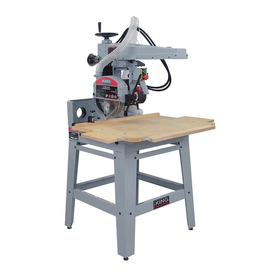
12” RADIAL ARM SAW 04/2017 MODELS: KC-12RAS (220V, 2 HP 1 PHASE) INSTRUCTION MANUAL KC-12RAS-230-3 (230V, 3 HP 3 PHASE) COPYRIGHT © 2016 ALL RIGHTS RESERVED BY KING CANADA TOOLS INC. -
Page 2: Warranty Information
WARRANTY INFORMATION 2-YEAR KING CANADA TOOLS LIMITED WARRANTY OFFERS A 2-YEAR LIMITED WARRANTY FOR THIS 12” RADIAL ARM SAW FOR COMMERCIAL USE. PROOF OF PURCHASE Please keep your dated proof of purchase for warranty and servicing purposes. REPLACEMENT PARTS Replacement parts for this product are available at our authorized King Canada service centres across Canada. LIMITED TOOL WARRANTY King Canada makes every effort to ensure that this product meets high quality and durability standards. -
Page 3: General Safety Instructions
GENERAL SAFETY INSTRUCTIONS VOLTAGE WARNING: Before connecting the machine to a power source (receptacle, outlet, etc.) be sure the voltage supplied is the same as that specified on the nameplate. A power source with voltage greater than specified can result in SERIOUS INJURY to the user - as well as damage the machine. -
Page 4: Electrical Information
2HP SINGLE PHASE MOTOR (MODEL KC-12RAS) OR A 230V, 3 HP Fig.3 is turned to the On position. To turn the machine “On” press the 3 PHASE MOTOR (KC-12RAS-230-3). IT IS VERY IMPORTANT TO green button (C) Fig.3. To stop the machine, push the red emergency MAKE SURE YOUR ELECTRICAL SYSTEM IS SUITABLE FOR THIS stop button (D). -
Page 5: Specifications
21. Head pivoting release/locking lever 28. Miter angle locking lever 22. Head locking handle 29. Column locking lock handle (top) SPECIFICATIONS MODEL KC-12RAS KC-12RAS-230-3 Blade diameter 12” 12” Blade arbor (with 1” bushing) 5/8” 5/8” Maximum depth of cut (10”/12” blade) 2”/ 3”... -
Page 6: Assembly And Setup
ASSEMbLY & SETUP WARNING! MAKE SURE THE SWITCH IS IN THE “OFF” POSITION AND THE POWER CORD IS UNPLUGGED. DO NOT PLUG POWER CORD OR TURN ON THE MACHINE UNTIL ALL ASSEMBLY AND INSTALLATION STEPS HAVE BEEN COMPLETED. ASSEMbLING STAND 1. Loosely assemble the stand legs (A) Fig.4 and the lower cross braces (B) together using carriage bolts and flange head hex. - Page 7 ASSEMbLY & SETUP INSTALLING DUST HOSE 1. Position a wire clamp (A) Fig.9 over one end of the clear flex dust hose (B). Slide hose onto blade guard (C) and secure hose to fitting by tightening the screw on the wire clamp (A). 2.
- Page 8 ASSEMbLY ADDENDUM WARNING! MAKE SURE THE SWITCH IS IN THE “OFF” POSITION AND THE POWER CORD IS UNPLUGGED. DO NOT PLUG POWER CORD OR TURN ON THE MACHINE UNTIL ALL ASSEMBLY AND INSTALLATION STEPS HAVE BEEN COMPLETED. ASSEMbLING HOLD DOWN 1. Thread the hold down threaded shaft (A) Fig.1 into the fixing bracket (B) then press the rubber hold down (C) to the end of the threaded shaft.
- Page 9 ASSEMbLY & SETUP INSTALLING bLADE WARNING! MAKE SURE THE SWITCH IS IN THE “OFF” POSITION AND THE POWER CORD IS UNPLUGGED. DO NOT PLUG POWER CORD OR TURN ON THE MACHINE UNTIL ALL BLADE INSTALLATION STEPS HAVE BEEN COMPLETED. 1. Unlock the head by turning lock lever (A) Fig.12 to the left. FIGURE 12 2.
-
Page 10: Assembly And Adjustments
ASSEMbLY & ADJUSTMENTS INSTALLING bLADE continued... WARNING! MAKE SURE THE SWITCH IS IN THE “OFF” POSITION AND THE POWER CORD IS UNPLUGGED. DO NOT PLUG POWER CORD OR TURN ON THE MACHINE UNTIL ALL BLADE INSTALLATION STEPS HAVE BEEN COMPLETED. 8. Install the 3 included laser batteries (LR44 1.5V batteries). Loosen and remove the two screws (A) Fig.16 and remove battery cover (B). - Page 11 ADJUSTMENTS ADJUSTING THE POSITION OF THE RADIAL HEAD 1. Loosen lock handle (A) Fig.20. 2. Slide the head to the desired position along the radial arm, retighten lock handle (A). FIGURE 20 ADJUSTING THE HEAD FOR MITER CUTS 1. Loosen lock handle (A) Fig.21. 2.
- Page 12 ADJUSTMENTS ADJUSTING THE HEAD FOR RIP CUTS continued... 3. Pull the head release lever (A) Fig.24 towards you, hold lever in place and rotate the head completely to the right as shown. 4. Push the head release lever (A) back to its original position as shown to secure. The head must be perfectly aligned in order for the lever to re-engage the locked position.
- Page 13 ADJUSTMENTS & OPERATION ADJUSTING ANTI-KICKbACK FINGERS TO PREVENT THE SAW “KERF” FROM CLOSING AND BINDING THE BLADE, WHICH CAN OVERLOAD AND/OR STALL THE MOTOR OR CAUSE THE BLADE TO LIFT AND EJECT THE WORKPIECE TOWARDS THE FRONT OF THE SAW AT VERY HIGH SPEEDS, ALWAYS USE THE ANTI-KICKBACK FINGERS AND RIVING DISC.
-
Page 14: Operation
OPERATION CONNECTING SAW TO DUST COLLECTOR IT IS HIGH RECOMMENDED TO CONNECT THIS MACHINE TO AN ADEQUATE DUST COLLECTOR. ALWAYS TURN DUST COLLECTOR ON BEFORE TURNING ON MACHINE. 1. Dual 4” dust ports (A) Fig.32 are provided to connect to a dust collector (not included) which has more than one inlet (2 required). - Page 15 OPERATION TYPES OF CUTS Inboard Rip Cuts NEVER USE THE SAW WITHOUT SAFETY GUARDS IN PLACE. MAKE SURE THE BLADE IS NOT IN CONTACT WITH THE WORKPIECE BEFORE STARTING SAW. 1. Disconnect the spring return (B) Fig.11 so the head can slide freely. 2.
-
Page 16: Operation And Maintenance
OPERATION & MAINTENANCE TYPES OF CUTS bevel Cuts NEVER USE THE SAW WITHOUT SAFETY GUARDS IN PLACE. MAKE SURE THE BLADE IS NOT IN CONTACT WITH THE WORKPIECE BEFORE STARTING SAW. 1. Raise the head to its highest position, this will allow space to tilt the head. 2. -
Page 17: Maintenance
MAINTENANCE MAINTENANCE MAKE SURE THE MACHINE HAS BEEN TURNED OFF AND UNPLUGGED FROM THE POWER SOURCE BEFORE PERFORMING ANY MAINTENANCE. SqUARING THE bLADE TO THE FENCE The blade is pre-set square (90°) to the fence at the factory, no further adjustments are required.