Table of Contents
Advertisement
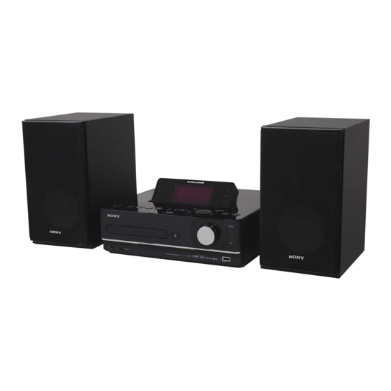
NAS-E35HD/SS-CE
SERVICE MANUAL
Ver. 1.0 2008.05
• SS-CE35HD is the speaker system of
NAS-E35HD.
Trademarks, etc.
You agree that you will use Gracenote Data, the Gracenote
• "GIGA JUKE" and its logo are trademarks of Sony
non-commercial use only. You agree not to assign, copy,
Corporation.
• Title Updater is a trademark of Sony Corporation.
Gracenote Data to any third party. YOU AGREE NOT
• "WALKMAN",
and
are
TO USE OR EXPLOIT GRACENOTE DATA, THE
registered trademarks of Sony Corporation.
GRACENOTE SOFTWARE, OR GRACENOTE SERVERS,
• MICROVAULT is a trademark of Sony Corporation.
EXCEPT AS EXPRESSLY PERMITTED HEREIN.
• MPEG Layer-3 audio coding technology and patents
You agree that your non-exclusive license to use the
•
Servers will terminate if you violate these restrictions.
Media are trademarks or registered trademarks of
If your license terminates, you agree to cease any and
countries.
and Gracenote Servers. Gracenote reserves all rights
•
Gracenote Servers, including all ownership rights. Under
such technology outside of this product is prohibited
no circumstances will Gracenote become liable for any
payment to you for any information that you provide. You
agree that Gracenote, Inc. may enforce its rights under this
• Built with Linter Database.
Agreement against you directly in its own name.
Copyright © 2006-2007, Brycen Corp., Ltd.
Copyright © 1990-2003, Relex, Inc., All rights reserved.
• Music recognition technology and related data are
provided by Gracenote®. Gracenote is the industry
service to count queries without knowing anything about
standard in music recognition technology and related
who you are. For more information, see the web page for
content delivery. For more information, please visit
the Gracenote Privacy Policy for the Gracenote service.
www.gracenote.com.
CD and music-related data from Gracenote, Inc.,
Data are licensed to you "AS IS. " Gracenote makes
no representations or warranties, express or implied,
regarding the accuracy of any Gracenote Data from in
service may practice one or more of the following U.S.
the Gracenote Servers. Gracenote reserves the right to
Patents: #5,987,525; #6,061,680; #6,154,773, #6,161,132,
delete data from the Gracenote Servers or to change data
#6,230,192, #6,230,207, #6,240,459, #6,330,593, and
other patents issued or pending. Some services supplied
under license from Open Globe, Inc. for U.S. Patent:
Gracenote Servers are error-free or that functioning
#6,304,523.
Gracenote and CDDB are registered trademarks of
uninterrupted. Gracenote is not obligated to provide you
with new enhanced or additional data types or categories
the "Powered by Gracenote" logo are trademarks of
that Gracenote may provide in the future and is free to
Gracenote.
discontinue its services at any time.
GRACENOTE DISCLAIMS ALL WARRANTIES
EXPRESS OR IMPLIED, INCLUDING, BUT
NOT LIMITED TO, IMPLIED WARRANTIES OF
MERCHANTABILITY, FITNESS FOR A PARTICULAR
PURPOSE, TITLE, AND NON-INFRINGEMENT.
GRACENOTE DOES NOT WARRANT THE RESULTS
Gracenote® End User License
THAT WILL BE OBTAINED BY YOUR USE OF THE
Agreement
GRACENOTE SOFTWARE OR ANY GRACENOTE
SERVER. IN NO CASE WILL GRACENOTE BE LIABLE
FOR ANY CONSEQUENTIAL OR INCIDENTAL
Gracenote, Inc. of Emeryville, California ("Gracenote").
DAMAGES OR FOR ANY LOST PROFITS OR LOST
REVENUES.
including name, artist, track, and title information
("Gracenote Data") from online servers or embedded
this manual are generally the trademarks or registered
databases (collectively, "Gracenote Servers") and to
trademarks of the manufacturer.
perform other functions. You may use Gracenote Data
™ and ® marks are omitted in this manual.
only by means of the intended End-User functions of this
application or device.
Sony Corporation
9-889-128-01
2008E05-1
Audio Business Group
©
2008.05
Published by Sony Techno Create Corporation
CD Section
HD Section
European model:
DIN power output (rated):
24 + 24 W (8 Ω at 1 kHz, DIN)
Continuous RMS power output
(reference):
30 + 30 W (8 Ω at 1 kHz, 10 % THD)
Music Power output (reference):
30 + 30 W (8 Ω at 1 kHz, 10 % THD)
Other models:
DIN power output (rated):
24 + 24 W (8 Ω at 1 kHz, DIN)
Continuous RMS power output
(reference):
30 + 30 W (8 Ω at 1 kHz, 10 % THD)
HDD Jukebox section
Capacity:
80 GB*
* A portion of the memory is used
for system management functions.
Actual available memory is approx.
72 GB.
names and product names indicated in
Model Name Using Similar Drive
Optical Pick-up Block Name
Model Name Using Similar Drive
Hard Disc Drive Name
SPECIFICATIONS
Recording system:
MP3
Maximum recording time (measured
with MP3 128 kbps):
About 1,300 h
Maximum number of tracks:
20,000
Maximum number of albums:
2,000
CD player section
System:
Compact disc and digital audio
system
Laser Diode Properties:
Emission duration: continuous
Laser Output*: Less than 44.6 μw
*
at a distance of 200 mm from the
objective lens surface on the Optical
Pick-up Block with 7 mm aperture.
Frequency response:
20 Hz - 20 kHz
HDD AUDIO SYSTEM
35HD
AEP Model
UK Model
E Model
Australian Model
NEW
KSM215DHAP
NEW
HDD/SG-NIGHTHAWK-S (80GB)
USB section
Supported bit rate
MP3 (MPEG-1 Audio Layer3):
32 - 320 kbps, VBR
WMA:
48 - 192 kbps, VBR
AAC:
48 - 320 kbps
Sampling frequencies
MP3 (MPEG-1 Audio Layer3):
32/44.1/48 kHz
WMA:
44.1 kHz
AAC:
44.1 kHz
– Continued on next page –
NAS-E35HD
SS-CE35HD
SPEAKER SYSTEM
Advertisement
Table of Contents

Related Manuals for Sony NAS-E35HD


Summary of Contents for Sony NAS-E35HD
-
Page 1: Specifications
SPECIFICATIONS Trademarks, etc. You agree that you will use Gracenote Data, the Gracenote • “GIGA JUKE” and its logo are trademarks of Sony non-commercial use only. You agree not to assign, copy, Corporation. • Title Updater is a trademark of Sony Corporation. -
Page 2: Notes On Chip Component Replacement
THE PARTS LIST ARE CRITICAL TO SAFE OPERATION. a CLASS 1 LASER product. REPLACE THESE COMPONENTS WITH SONY PARTS This marking is located on the WHOSE PART NUMBERS APPEAR AS SHOWN IN THIS rear or bottom exterior. MANUAL OR IN SUPPLEMENTS PUBLISHED BY SONY. -
Page 3: Table Of Contents
NAS-E35HD/SS-CE35HD TABLE OF CONTENTS SERVICING NOTES EXPLODED VIEWS ..........7-1. Panel Section ..............73 GENERAL 7-2. Top Panel Section ............74 ..............7-3. Main Section ..............75 7-4. HDD Section ..............76 DISASSEMBLY 7-5. Chassis Section ............... 77 3-1. Disassembly Flow ............ -
Page 4: Servicing Notes
NAS-E35HD/SS-CE35HD SECTION 1 SERVICING NOTES NOTE THE IC1, IC5 AND IC13 ON THE USB MICOM NOTES ON HANDLING THE OPTICAL PICK-UP BOARD REPLACING BLOCK OR BASE UNIT IC1, IC5 and IC13 on the USB MICOM board cannot exchange with single. When IC1, IC5 and IC13 on the USB MICOM board The laser diode in the optical pick-up block may suffer electrostat- are damaged, exchange the entire mounted board. - Page 5 NAS-E35HD/SS-CE35HD HOW TO OPEN THE TRAY WHEN POWER SWITCH TURN OFF Note: Please insert a screwdriver after removing the panel (side L). About disassembly of the panel (side L), please refer to “3-2. Panel (Side L/R)” (page 13). Open the tray.
-
Page 6: General
NAS-E35HD/SS-CE35HD SECTION 2 This section is extracted GENERAL from instruction manual. Remote control CLOCK/TIMER buttons SLEEP button timer Use to set the clock or timer. • SELECT button setting. Playback buttons timer setting. Use to select the function directly and •... - Page 7 NAS-E35HD/SS-CE35HD Top of the main unit FUNCTION button Menu operation buttons Use to select menu items and enter menu Use to select a function. settings. Playback buttons • , , and buttons Use to select the function directly and start Use to select a menu item or to change a playback at the same time.
-
Page 8: Disassembly
NAS-E35HD/SS-CE35HD SECTION 3 DISASSEMBLY • This set can be disassembled in the order shown below. 3-1. DISASSEMBLY FLOW 3-2. PANEL (SIDE L/R) (Page 9) 3-3. TOP PANEL BLOCK (Page 9) 3-4. HP JACK BOARD, 3-6. FL BLOCK KEY (FRONT) BOARD,... -
Page 9: Panel (Side L/R)
NAS-E35HD/SS-CE35HD Note: Follow the disassembly procedure in the numerical order given. 3-2. PANEL (SIDE L/R) screw (BVTP3 × 8) panel (side L) screw (BVTP3 × 8) screw (BVTP3 × 6) panel (side R) screw (BVTP3 × 6) 3-3. TOP PANEL BLOCK... -
Page 10: Hp Jack Board, Key (Front) Board, Panel (Front) Assy
NAS-E35HD/SS-CE35HD 3-4. HP JACK BOARD, KEY (FRONT) BOARD, PANEL (FRONT) ASSY connector (CN303) two screws (B2.6) screw (B2.6) hold board HP JACK board screw (BVTP3 × 6) plate (key front PWB) flexible flat cable (5 core) (CNP601) four screws (B2.6) -
Page 11: Fl Block
NAS-E35HD/SS-CE35HD 3-6. FL BLOCK Note: This illustration is seeing of top panel block from the inside. two screws (BVTP3 × 6) flexible flat cable (9 core) (CNP404) screw (BVTP3 × 6) FL block 3-7. DISPLAY BOARD Remove solders. case (FL) assy... -
Page 12: Dab Board, Dmp Board, Tuner (Fm/Am)
NAS-E35HD/SS-CE35HD 3-8. DAB BOARD, DMP BOARD, TUNER (FM/AM) screw (BVTP3 × 6) barrier (tuner) two screws (BVTP3 × 6) shield plate (tuner) bracket (DMP) DMP board two screws (BVTP3 × 6) tuner (FM/AM) Remove the solder. two screws coaxial connector (B2.6) -
Page 13: Main Board
NAS-E35HD/SS-CE35HD 3-9. MAIN BOARD flexible flat cable (5 core) four screws (CNP810) (BVTP3 × 6) flexible flat cable (5 core) (CNP601) MAIN board (with flexible flat cable (11 core/5core)) Remove the solder. Remove the solder. flexible flat cable (11 core) -
Page 14: Usb Micom Board
NAS-E35HD/SS-CE35HD 3-11. USB MICOM BOARD flexible flat cable (5 core) (CN2) shield plate (USB MICOM PWB) four screws (BVTP3 × 6) flexible flat cable (17 core) USB MICOM board (CN3) four screws chassis (USB MICOM PWB) (BVTP3 × 6) connector (CN7) -
Page 15: Base Unit
NAS-E35HD/SS-CE35HD 3-13. BASE UNIT floating screw insulator two floating screws two springs (insulator) two floating screws insulator two springs (insulator) base unit insulator insulator loading (BK) assy – Bottom view – 3-14. BELT position of belt belt belt claw claw... -
Page 16: Op Base Assy (Ksm215Dhap)
NAS-E35HD/SS-CE35HD 3-15. OP BASE ASSY (KSM215DHAP) op base assy (KSM215DHAP) flexible flat cable (16 core) (CN301) CD board Remove four solders. -
Page 17: Test Mode
NAS-E35HD/SS-CE35HD SECTION 4 TEST MODE COLD RESET CD TRAY LOCK The cold reset clears all data including preset data stored in the This mode is for the antitheft of CD disc in shop. (not for trans- memory to initial conditions. Execute this mode when returning port) the set to the customer. - Page 18 3. The version of CDDB is displayed on the fl uorescent indicator 6. Initialization Mode For Factory tube. The user use areas other than the “Sony Demo” artist in HDD are initialized, and the cold reset is executed. 2. Custom DB Initialization Procedure: The initialization of custom DB recorded in HDD is executed.
- Page 19 NAS-E35HD/SS-CE35HD HDD TITLE UPDATE TEST MODE The title updater version display and title updater update can be executed in this mode. Enter The HDD Title Update Test Mode Procedure: 1. In the standby status, press the [ ] button to turn the power 2.
-
Page 20: Electrical Checks
NAS-E35HD/SS-CE35HD SECTION 5 ELECTRICAL CHECKS Connecting and Adjustment Location: CD board CD SECTION – CD BOARD (CONDUCTOR SIDE) – Note: 1. CD Block is basically designed to operate without adjustment. There- fore, check each item in order given. 2. Use YEDS-18 disc (3-702-101-01) unless otherwise indicated. -
Page 21: Diagrams
NAS-E35HD/SS-CE35HD SECTION 6 DIAGRAMS 6-1. BLOCK DIAGRAM - CD SERVO, PANEL Section - DISPLAY CONTROLLER IC403 DIGITAL SERVO, DIGITAL SIGNAL PROCESSOR, D/A CONVERTER OPTICAL PICK-UP IC201 D410 BLOCK LED DRIVE LED_HDD 18 (KSM215DHAP) XOUT Q410 (Page 23) CD-L AOUT1 X401... -
Page 22: Block Diagram - Usb, Hdd Section
NAS-E35HD/SS-CE35HD 6-2. BLOCK DIAGRAM - USB, HDD Section - DATA BUFFER IC11 USB SYSTEM CONTROLLER IC2 (2/2) A/D CONVERTER, D/A CONVERTER IC12 (Page 23) LRCKO 12 LRCKI SDTI 8 DOUT VOUTL 8 BCKI 9 DIN VOUTR R–CH BCKO SDTO_O (Page 21) -
Page 23: Block Diagram - Main Section
NAS-E35HD/SS-CE35HD 6-3. BLOCK DIAGRAM - MAIN Section - J303 INPUT SELECTOR INPUT SELECTOR, ELECTRICAL VOLUME IC351 IC302 DIGITAL POWER AMP SPEAKER IC352 LINE (Page 22) X 13 IN-L1 OUT L 23 5 LINP LOUTP IC307 LOUTP LOUTN – (Page 21) -
Page 24: Block Diagram - Power Supply Section
NAS-E35HD/SS-CE35HD 6-4. BLOCK DIAGRAM - POWER SUPPLY Section - D913 PROTECT D914, 929 D912 D928 D925 P MONI SWITCH Q802 D926 D927 Q904 D920 MAIN POWER D922 REGULATOR TRANSFORMER IC301 B+ Q302 D919 D905 D906 D918 RECT REGULATOR D903 IC908... - Page 25 NAS-E35HD/SS-CE35HD THIS NOTE IS COMMON FOR PRINTED WIRING BOARDS AND SCHEMATIC DIAGRAMS. • Circuit Boards Location (In addition to this, the necessary note is printed in each block.) DMP board For Printed Wiring Boards. For Schematic Diagrams. Note: Note: D/D CON board •...
-
Page 26: Printed Wiring Board - Cd Board
NAS-E35HD/SS-CE35HD 6-5. PRINTED WIRING BOARD - CD Board - • See page 25 for Circuit Boards Location. • : Uses unleaded solder. (Page 37) IC201 C259 NAS-E35HD/SS-CE35HD... -
Page 27: Schematic Diagram - Cd Board
NAS-E35HD/SS-CE35HD 6-6. SCHEMATIC DIAGRAM - CD Board - • See page 43 for waveforms. • See page 54 for IC Block Diagrams. CD BOARD R302 CN301 TP313 R301 C301 TP312 C323 R321 TP311 C264 C208 TP314 R324 TP310 C322 R260... -
Page 28: Schematic Diagram - Usb Micom Board (1/4)
NAS-E35HD/SS-CE35HD 6-7. SCHEMATIC DIAGRAM - USB MICOM Board (1/4) - • See page 43 for waveforms. • See page 54 for IC Block Diagrams. • See page 64 for IC Pin Function Description. USB MICOM BOARD (1/4) IC B/D C133... -
Page 29: Schematic Diagram - Usb Micom Board (2/4)
NAS-E35HD/SS-CE35HD 6-8. SCHEMATIC DIAGRAM - USB MICOM Board (2/4) - • See page 43 for waveforms. • See page 54 for IC Block Diagrams. • See page 64 for IC Pin Function Description. USB MICOM BOARD (2/4) R75 0 C144... -
Page 30: Schematic Diagram - Usb Micom Board (3/4)
NAS-E35HD/SS-CE35HD 6-9. SCHEMATIC DIAGRAM - USB MICOM Board (3/4) - • See page 43 for waveforms. • See page 54 for IC Block Diagrams. (Page 28) (Page 29) USB MICOM USB MICOM BOARD BOARD (1/4) (2/4) USB MICOM BOARD (3/4) -
Page 31: Schematic Diagram - Usb Micom Board (4/4)
NAS-E35HD/SS-CE35HD 6-10. SCHEMATIC DIAGRAM - USB MICOM Board (4/4) - • See page 43 for waveforms. • See page 54 for IC Block Diagrams. • See page 64 for IC Pin Function Description. (Page 28) (Page 29) USB MICOM USB MICOM... -
Page 32: Printed Wiring Board - Usb Micom Board
NAS-E35HD/SS-CE35HD 6-11. PRINTED WIRING BOARD - USB MICOM Board - • See page 25 for Circuit Boards Location. • : Uses unleaded solder. USB MICOM BOARD (COMPONENT SIDE) USB MICOM BOARD (CONDUCTOR SIDE) D/D CON BOARD KH907 (Page 50) R150... -
Page 33: Schematic Diagram - Main Board (1/3)
NAS-E35HD/SS-CE35HD 6-12. SCHEMATIC DIAGRAM - MAIN Board (1/3) - • See page 43 for waveforms. • See page 54 for IC Block Diagrams. • See page 64 for IC Pin Function Description. (1/3) OPEN/CLOSE OPEN/CLOSE VOLUME SIRCS DGND EVER3.3V FFC809 FFC808 3.3V... -
Page 34: Schematic Diagram - Main Board (2/3)
NAS-E35HD/SS-CE35HD 6-13. SCHEMATIC DIAGRAM - MAIN Board (2/3) - • See page 54 for IC Block Diagrams. ANTENNA (Page 39) (Page 41) 75Ω (Page 39) TUNER (FM/AM) CNP801 11P (AEP,UK) CNP803 CNP808 (EXCEPT AEP,UK) (AEP,UK) CNP802 CNP301 (2/3) R113 R214... -
Page 35: Schematic Diagram - Main Board (3/3)
NAS-E35HD/SS-CE35HD 6-14. SCHEMATIC DIAGRAM - MAIN Board (3/3) - • See page 54 for IC Block Diagrams. (Page 34) (3/3) C105 0.47 C152 0.47 C136 C134 C205 R134 R234 0.47 R133 Q305 C117 1 50V RT1N141C C137 C252 INVERTER 0.47... -
Page 36: Main Board (Component Side)
NAS-E35HD/SS-CE35HD • Semiconductor 6-15. PRINTED WIRING BOARD - MAIN Board (Component Side) - • See page 25 for Circuit Boards Location. • : Uses unleaded solder. Location Ref. No. Location D801 D803 MAIN BOARD (COMPONENT SIDE) D805 D809 IC301 IC302... -
Page 37: Printed Wiring Board - Main Board (Conductor Side)
NAS-E35HD/SS-CE35HD 6-16. PRINTED WIRING BOARD - MAIN Board (Conductor Side) - • Semiconductor • See page 25 for Circuit Boards Location. • : Uses unleaded solder. Location Ref. No. Location D804 (Page 32) (Page 26) (Page 54) D806 USB MICOM... -
Page 38: Printed Wiring Boards - Dab, Dmp Section
NAS-E35HD/SS-CE35HD • See page 25 for Circuit Boards Location. • : Uses unleaded solder. 6-17. PRINTED WIRING BOARDS - DAB, DMP Section - DAB BOARD DMP BOARD (SIDE B) DMP BOARD (SIDE A) IC651 C673 J811 DMPORT R659 IC652 R974... -
Page 39: Schematic Diagram - Dab, Dmp Section
NAS-E35HD/SS-CE35HD 6-18. SCHEMATIC DIAGRAM - DAB, DMP Section - • See page 54 for IC Block Diagrams. (UK) C173 R320 100k J601 DAB601 DAB TUNER MODULE 75Ω LINE AMP C273 CN602 R323 IC304 100k NJM4558M-TE2 R325 4.7k C176 470p R176... -
Page 40: Printed Wiring Board - D-Amp Board
NAS-E35HD/SS-CE35HD 6-19. PRINTED WIRING BOARD - D-AMP Board - • See page 25 for Circuit Boards Location. • : Uses unleaded solder. (Page 42) SP TERMINAL (COMPONENT SIDE) D-AMP BORD (CONDUCTOR SIDE) D-AMP BORD BOARD CN306 R257 KH352 R258 Q355... -
Page 41: Schematic Diagram - D-Amp Board
NAS-E35HD/SS-CE35HD 6-20. SCHEMATIC DIAGRAM - D-AMP Board - • See page 43 for waveforms. • See page 54 for IC Block Diagrams. CNP351 PROTECT SHUTDOWN SP_MUTE Q353 R356 AGND-R D351 2SC3052 MAZ8150G0LS0 AMP-R RESET SWITCH R378 C355 EB351 R375 C356... -
Page 42: Printed Wiring Boards - Speaker Section
NAS-E35HD/SS-CE35HD 6-21. PRINTED WIRING BOARDS - SPEAKER Section - 6-22. SCHEMATIC DIAGRAM - SPEAKER Section - • See page 25 for Circuit Boards Location. • : Uses unleaded solder. SP TERMINAL BOARD J303 SPEAKER D-AMP BOARD KH352 (Page 40) CN306... - Page 43 NAS-E35HD/SS-CE35HD • Waveforms – D-AMP Board – – DISPLAY Board – – CD Board – – USB MICOM Board – – MAIN Board – IC201 (TEI) IC10 (1A) IC803 (XCOUT) IC352 (ROSC) IC403 (XOUT) (CD play mode) (USB play mode) Approx.
-
Page 44: Display Board (Component Side)
NAS-E35HD/SS-CE35HD 6-23. PRINTED WIRING BOARD - DISPLAY Board (Component Side) - • See page 25 for Circuit Boards Location. • : Uses unleaded solder. DISPLAY BOARD (COMPONENT SIDE) 1-876-376- (11) NAS-E35HD/SS-CE35HD... -
Page 45: Printed Wiring Board - Display Board (Conductor Side)
NAS-E35HD/SS-CE35HD 6-24. PRINTED WIRING BOARD - DISPLAY Board (Conductor Side) - • See page 25 for Circuit Boards Location. • : Uses unleaded solder. (CONDUCTOR SIDE) (NC) DISPLAY BOARD FFC405 TUNER DMPORT FL401 FLUORESCENT INDICATOR TUBE AUDIO IN (11) D/D CON... -
Page 46: Schematic Diagram - Display Board (1/2)
NAS-E35HD/SS-CE35HD 6-25. SCHEMATIC DIAGRAM - DISPLAY Board (1/2) - • See page 43 for waveforms. • See page 54 for IC Block Diagrams. • See page 64 for IC Pin Function Description. (1/2) CNP404 EVER 3.3V STBY LED POWER KEY... -
Page 47: Schematic Diagram - Display Board (2/2)
NAS-E35HD/SS-CE35HD 6-26. SCHEMATIC DIAGRAM - DISPLAY Board (2/2) - • See page 43 for waveforms. • See page 54 for IC Block Diagrams. (2/2) FL401 VACUUM FLUORESCENT DISPLAY R447 R531 R532 R546 R547 R552 R553 R536 R537 R556 R557 R541... -
Page 48: Printed Wiring Boards - Panel Section
NAS-E35HD/SS-CE35HD • See page 25 for Circuit Boards Location. • : Uses unleaded solder. 6-27. PRINTED WIRING BOARDS - PANEL Section - • Semiconductor KEY (FRONT) BOARD Location KEY (R) BOARD KEY (L) BOARD Ref. No. Location D601 D851 TUNE +... -
Page 49: Schematic Diagram - Panel Section
NAS-E35HD/SS-CE35HD 6-28. SCHEMATIC DIAGRAM - PANEL Section - D601,S610 S602 ROTARY S610 ENCODER IC601 NJL24H400B R615 VOLUME D601 SLR-343VCT32 LED DRIVE REMOTE CONTROL Q601 2SC3052 RECEIVER EVER 3.3V R614 LED DRIVE S601 STBY LED POWER KEY DGND FFC601 R601 CNP601... -
Page 50: Printed Wiring Board - D/D Con Board
NAS-E35HD/SS-CE35HD 6-29. PRINTED WIRING BOARD - D/D CON Board - • See page 25 for Circuit Boards Location. • : Uses unleaded solder. • Semiconductor Location Ref. No. Location D/D CON BOARD D905 D906 USB MICOM BOARD D908 D916 D909... -
Page 51: Schematic Diagram - D/D Con Board
NAS-E35HD/SS-CE35HD 6-30. SCHEMATIC DIAGRAM - D/D CON Board - • See page 54 for IC Block Diagrams. R959 C925 C954 CN903 220k FAN12/10V M901 R970 47 1/2W (FAN) R958 220k IC908 R957 KIA7809API +9V REGULATOR REGULATOR C953 C950 IC905 CNP904... -
Page 52: Printed Wiring Board - Power Board
NAS-E35HD/SS-CE35HD 6-31. PRINTED WIRING BOARD - POWER Board - • See page 25 for Circuit Boards Location. • : Uses unleaded solder. POWER BOARD VOLTAGE SELECTOR 220 – 240V 120V (E51) JW011 JW01 (MX) JW008 TH01 JW009 IC02 (E51) VR002... -
Page 53: Schematic Diagram - Power Board
NAS-E35HD/SS-CE35HD 6-32. SCHEMATIC DIAGRAM - POWER Board - • See page 54 for IC Block Diagrams. • See page 64 for IC Pin Function Description. CNP902 R914 R915 POWER_ON CN01 +4VSB T5AL (AC IN) FH01 DGND 250V FH02 R919 AC_L... -
Page 54: Printed Wiring Board - Motor Board
NAS-E35HD/SS-CE35HD 6-33. PRINTED WIRING BOARD - MOTOR Board - • IC Block Diagrams • See page 25 for Circuit Boards Location. • : Uses unleaded solder. – CD Board – IC201 CXD3059AR MOTOR BOARD 116 115 114 112 111 110 109... - Page 55 NAS-E35HD/SS-CE35HD IC401 AN41050 PVCC/2 DIRECTION DETECTION DIRECTION DETECTION DIRECTION DETECTION PVCC/2 DIRECTION DETECTION RESET CIRCUIT . STANDBY . BAND-GAP . SVCC...
- Page 56 NAS-E35HD/SS-CE35HD – USB MICOM Board – IC4 S1R72005F00A300 37 36 35 34 33 32 XI CLKs CONTROLLER 31 XO HVSS 30 LVDD FIFO SDRAM 29 TIN0 (2.5KB) 28 TIN1 CD15 27 TIN2 CD14 CD13 26 ID CD12 HOST CD11 25 xRPUEN...
- Page 57 NAS-E35HD/SS-CE35HD IC6 MM1663DHBE IC7 SN74LVC138APWR-12 DATA OUTPUTS 8 7 6 5 THERMAL BIAS SHUTDOWN DRIVER CURRENT LIMITTER REFERENCE OUTPUT SELECT ENABLE IC8 S-1132B25-U5T1G IC10 TC7WHU04FU (TE12R) VOUT 1 OVERCURRENT PROTECTION ON/OFF ON/OFF CONTROL – VSS 2 REFERENCE VOLTAGE NC 3...
- Page 58 NAS-E35HD/SS-CE35HD IC11 DIR9001S1PWRG4 18 17 16 FUNCTION RESET CONTROL PREAMBLE DETECTOR CHARGE PUMP CLOCK BIPHASE DECODER DATA DECODER SERIAL AUDIO DATA CLOCK AND DATA RECOVERY FORMATTER AUDIO DATA MUTE CONTROL ERROR DIVIDER DIVIDER DECODER DETECTOR CHANNEL STATUS USER DATA OUTPUT...
- Page 59 NAS-E35HD/SS-CE35HD IC14 TPS2051BDRG4 CHARGE PUMP CURRENT DRIVER LIMIT UVLO THERMAL SENCE – DAB Board – IC651 TK11133CSCL-G IC652 MM3291CNRE REGULATOR VDD 1 VOUT GND 2 OVER HEAT & CE 3 OVER CURRENT PROTECTION CONTROL – CIRCUIT BANDGAP REFERENCE – MAIN Board –...
- Page 60 NAS-E35HD/SS-CE35HD IC351 BU4052BCF-E2 IC801 PST3629NR OUT 1 VDD 2 2-COM – 1-COM VREF GND 3 IC805 BA6956AN IC981, 982 TK11133CSCL-G OVER HEAT & OVER CURRENT CONTROL LOGIC PROTECTION CONTROL – CIRCUIT BANDGAP REFERENCE...
- Page 61 NAS-E35HD/SS-CE35HD – D-AMP Board – IC352 TPA3100D2PHPR 48 47 AVCC SC DETECT VBYP AVCC THERMAL VREG BIASES STARTUP & PROTECTION VREGOK REGULATOR REFERENCE LOGIC AVCC VCCOK TLL INPUT BUFFER (VCC COMPLIANT) TLL INPUT BUFFER (VCC COMPLIANT) VREG GAIN GAIN VCLAMP...
- Page 62 NAS-E35HD/SS-CE35HD – DISPLAY Board – IC401 SN74LV123ANSR IC404 TK11133CSCL-G OVER HEAT & OVER CURRENT PROTECTION CONTROL – CIRCUIT BANDGAP REFERENCE – D/D CON Board – IC904, 906 SI-8050S-LF1101 IC902 PQ1CG2032FZ IC907 SI-8120S OVER VOLTAGE ON/OFF REGULATOR CURRENT REGULATOR CIRCUIT PROTECTOR...
- Page 63 NAS-E35HD/SS-CE35HD – POWER Board – IC01 MIP2F20MS1SO 6.6V 8 SOURCE 7 SOURCE VDD CLAMP ILIMIT CIRCUIT CONSTANT CORRECTION CURRENT CIRCUIT SOURCE CLAMP CIRCUIT – (ILIMIT SETTING) DRAIN CURRENT DETECT FOR LIGHT LOAD DETECTION INTERMITTENT OSCILLATION CONTROL – AT TURNING ON VCL.OUT...
- Page 64 NAS-E35HD/SS-CE35HD • IC Pin Function Description USB MICOM BOARD IC2 D708E001BRFP266 (USB SYSTEM CONTROLLER) Pin No. Pin Name Description Ground terminal EM_A (_18), 2, 3 Address signal output to the fl ash memory EM_A (_13) CD-PO Power supply on/off control signal output terminal for the CD section "H": power on...
- Page 65 NAS-E35HD/SS-CE35HD Pin No. Pin Name Description 63, 64 EM_D (10), EM_D (9) Two-way data bus with the SDRAM, fl ash memory and USB interface CVDD Power supply terminal (+1.2V) EM_D (8) Two-way data bus with the SDRAM, fl ash memory and USB interface...
- Page 66 NAS-E35HD/SS-CE35HD Pin No. Pin Name Description Ground terminal DVDD Power supply terminal (+3.3V) USB_INT Interrupt signal input from the USB interface AC_DET Power failure detection output terminal for the USB section CVDD Power supply terminal (+1.2V) Ground terminal BD_XTACN Oscillation circuit on/off control signal output to the digital servo EM_A (_14) Address signal output to the fl...
- Page 67 NAS-E35HD/SS-CE35HD USB MICOM BOARD IC9 JM20339-LGCA0C (HARD DISK DRIVER) Pin No. Pin Name Description 1 to 3 GPIO21 to GPIO23 Not used MODE2 Not used 5, 6 Not used DGND Ground terminal VCCO Power supply terminal (+3.3V) 9, 10 Not used...
- Page 68 NAS-E35HD/SS-CE35HD USB MICOM BOARD IC13 USB2512-AEZG (USB 2.0 HUB CONTROLLER) Pin No. Pin Name Description USBDN1_DM, 1, 2 Audio serial data input/output with the USB connector USBDN1_DP USBDN2_DM, 3, 4 Audio serial data input/output with the hard disk driver USBDN2_DP VDDA33 Power supply terminal (+3.3V)
- Page 69 NAS-E35HD/SS-CE35HD MAIN BOARD IC803 R5F3640DDFA (SYSTEM CONTROLLER) Pin No. Pin Name Description Audio source selection signal output to the input selector HP DET Headphone detection signal input terminal "H": headphone has been inserted GC_RESET Reset signal output to the display controller "L": reset...
- Page 70 NAS-E35HD/SS-CE35HD Pin No. Pin Name Description KEY_WAKE_UP_ Key input terminal for the power key (A/D input) POWER Not used XDM_PROTECT Protect signal input from the DMPORT section CLINK_TXD_OUT Serial data output to the DMPORT connector CLINK_RXD_IN Serial data input from the DMPORT connector...
- Page 71 NAS-E35HD/SS-CE35HD DISPLAY BOARD IC403 R5F3640DDFA (DISPLAY CONTROLLER) Pin No. Pin Name Description Not used SOFT-TEST Not used Not used Power supply ON/OFF control signal output terminal for the liquid crystal display VFD_POWER "H": power ON LED_DATA Not used LED_LAT Not used...
- Page 72 NAS-E35HD/SS-CE35HD POWER BOARD IC02 CXD9841P (POWER CONTROL) Pin No. Pin Name Description VSENSE AC line input voltage detection signal input terminal Feedback signal input terminal for frequency modulation of oscillator External capacitor connection terminal for oscillator External resistor connection terminal for oscillator...
-
Page 73: Exploded Views
NAS-E35HD/SS-CE35HD SECTION 7 EXPLODED VIEWS Note: • -XX and -X mean standardized parts, so • Color Indication of Appearance Parts Ex- The components identifi ed by mark 0 they may have some difference from the ample: or dotted line with mark 0 are critical for original one. -
Page 74: Top Panel Section
NAS-E35HD/SS-CE35HD 7-2. TOP PANEL SECTION FL401 not supplied not supplied DISPLAY board not supplied not supplied not supplied (KEY (L) board) not supplied (KEY (R) board) not supplied Ref. No. Part No. Description Remark Ref. No. Part No. Description Remark 2-633-134-01 SCREW (B2.6), (+) BV TAPPING... -
Page 75: Main Section
NAS-E35HD/SS-CE35HD 7-3. MAIN SECTION not supplied not supplied loading mechanism section HDD section Ref. No. Part No. Description Remark Ref. No. Part No. Description Remark A-1498-599-A MAIN BOARD, COMPLETE (AEP) 3-280-185-01 PLATE (CD TRAY), ORNAMENTAL A-1536-379-A MAIN BOARD, COMPLETE (RU) -
Page 76: Hdd Section
NAS-E35HD/SS-CE35HD 7-4. HDD SECTION not supplied not supplied (USB MICOM board) not supplied (AUS) (AEP, UK, RU, E51. MX) not supplied chassis section not supplied not supplied not supplied (USB JACK board) not supplied Ref. No. Part No. Description Remark Ref. -
Page 77: Chassis Section
NAS-E35HD/SS-CE35HD 7-5. CHASSIS SECTION not supplied not supplied DAB601 (UK) (AUS) J601 not supplied supplied not supplied (UK) not supplied not supplied supplied (SP TERMINAL board) not supplied supplied not supplied Ref. No. Part No. Description Remark Ref. No. Part No. -
Page 78: Loading Mechanism Section
NAS-E35HD/SS-CE35HD 7-6. LOADING MECHANISM SECTION not supplied not supplied (MOTOR board) not supplied base unit section Ref. No. Part No. Description Remark Ref. No. Part No. Description Remark A-1242-967-A LOADING (BK) ASSY 4-227-045-41 SPRING (INSULATOR) 3-080-478-01 BELT 4-229-005-41 INSULATOR 4-985-672-01... -
Page 79: Base Unit Section
NAS-E35HD/SS-CE35HD 7-7. BASE UNIT SECTION (including sled motor (M402), spindle motor (M401)) spindle motor (M401) sled motor (M402) Ref. No. Part No. Description Remark Ref. No. Part No. Description Remark A-1498-560-A CD BOARD, COMPLETE 0 301 8-820-272-02 OPTICAL PICK-UP BLOCK (KSM215DHAP/C2NP) -
Page 80: Speaker Section (Ss-Ce35Hd)
NAS-E35HD/SS-CE35HD 7-8. SPEAKER SECTION (SS-CE35HD) not supplied Ref. No. Part No. Description Remark Ref. No. Part No. Description Remark A-1508-681-A SYSTEM (L) ASSY (Lch) (AEP, UK, RU, AUS) A-1508-707-A SYSTEM (R) ASSY (Rch) (E51, MX, AR) A-1508-706-A SYSTEM (L) ASSY (Lch) (E51, MX, AR) -
Page 81: Electrical Parts List
NAS-E35HD/SS-CE35HD SECTION 8 ELECTRICAL PARTS LIST Note: • Due to standardization, replacements in • COILS • Abbreviation the parts list may be different from the uH: μH : Australian model parts specifi ed in the diagrams or the com- • RESISTORS : Chilean and Peruvian models ponents used on the set. - Page 82 NAS-E35HD/SS-CE35HD D-AMP Ref. No. Part No. Description Remark Ref. No. Part No. Description Remark C158 1-137-980-91 CERAMIC CHIP 0.47uF R252 1-216-835-11 METAL CHIP 1/10W C161 1-115-339-11 CERAMIC CHIP 0.1uF R253 1-216-821-11 METAL CHIP 1/10W C162 1-137-980-91 CERAMIC CHIP 0.47uF R254...
- Page 83 NAS-E35HD/SS-CE35HD D-AMP D/D CON Ref. No. Part No. Description Remark Ref. No. Part No. Description Remark < COIL > C922 1-107-826-11 CERAMIC CHIP 0.1uF C923 1-112-231-11 ELECT 2200uF L151 1-457-387-11 INDUCTOR 22uH C924 1-127-715-11 CERAMIC CHIP 0.22uF L251 1-457-387-11 INDUCTOR...
- Page 84 NAS-E35HD/SS-CE35HD D/D CON Ref. No. Part No. Description Remark Ref. No. Part No. Description Remark R980 1-216-829-11 METAL CHIP 4.7K 1/10W < IC > ************************************************************ IC902 8-759-640-19 IC PQ1CG2032FZ A-1536-385-A DAB BOARD, COMPLETE (UK) IC904 8-759-474-09 IC SI-8050S-LF1101 ******************** IC905...
- Page 85 NAS-E35HD/SS-CE35HD DISPLAY Ref. No. Part No. Description Remark Ref. No. Part No. Description Remark < COIL > C429 1-107-826-11 CERAMIC CHIP 0.1uF C430 1-107-826-11 CERAMIC CHIP 0.1uF L651 1-469-152-11 FERRITE, EMI (SMD) (2012) C431 1-164-156-11 CERAMIC CHIP 0.1uF L652 1-469-152-11...
- Page 86 NAS-E35HD/SS-CE35HD DISPLAY Ref. No. Part No. Description Remark Ref. No. Part No. Description Remark Q412 8-729-620-07 TRANSISTOR 2SC3052EF-T1-LEF Q413 8-729-620-07 TRANSISTOR 2SC3052EF-T1-LEF R466 1-216-809-11 METAL CHIP 1/10W Q414 8-729-620-07 TRANSISTOR 2SC3052EF-T1-LEF R467 1-216-833-11 METAL CHIP 1/10W Q415 8-729-620-07 TRANSISTOR 2SC3052EF-T1-LEF...
- Page 87 NAS-E35HD/SS-CE35HD HP JACK KEY (FRONT) KEY (L) Ref. No. Part No. Description Remark Ref. No. Part No. Description Remark < FERRITE BEAD/RESISTOR > C239 1-126-193-11 ELECT CHIP C964 1-126-205-11 ELECT CHIP 47uF 6.3V FB101 1-469-324-21 FERRITE, EMI (SMD) (2012) C965 1-164-156-11 CERAMIC CHIP 0.1uF...
- Page 88 NAS-E35HD/SS-CE35HD KEY (L) KEY (R) MAIN Ref. No. Part No. Description Remark Ref. No. Part No. Description Remark C107 1-115-467-11 CERAMIC CHIP 0.22uF R612 1-216-821-11 METAL CHIP 1/10W C108 1-164-360-11 CERAMIC CHIP 0.1uF R614 1-216-833-11 METAL CHIP 1/10W C110 1-162-962-11...
- Page 89 NAS-E35HD/SS-CE35HD MAIN Ref. No. Part No. Description Remark Ref. No. Part No. Description Remark C241 1-164-360-11 CERAMIC CHIP 0.1uF C986 1-126-157-11 ELECT 10uF C242 1-126-160-11 ELECT 50V (UK) C987 1-164-360-11 CERAMIC CHIP 0.1uF C243 1-126-160-11 ELECT C988 1-164-360-11 CERAMIC CHIP 0.1uF...
- Page 90 NAS-E35HD/SS-CE35HD MAIN Ref. No. Part No. Description Remark Ref. No. Part No. Description Remark R126 1-216-837-11 METAL CHIP 1/10W < COIL > (E51, MX, AR) R128 1-216-821-11 METAL CHIP 1/10W L803 1-410-509-11 INDUCTOR 10uH (UK) L804 1-410-509-11 INDUCTOR 10uH R129...
- Page 91 NAS-E35HD/SS-CE35HD MAIN Ref. No. Part No. Description Remark Ref. No. Part No. Description Remark R231 1-216-821-11 METAL CHIP 1/10W R714 1-216-821-11 METAL CHIP 1/10W R716 1-216-821-11 METAL CHIP 1/10W R232 1-216-841-11 METAL CHIP 1/10W R800 1-216-821-11 METAL CHIP 1/10W R233...
- Page 92 NAS-E35HD/SS-CE35HD MAIN MOTOR POWER Ref. No. Part No. Description Remark Ref. No. Part No. Description Remark R853 1-216-821-11 METAL CHIP 1/10W < SWITCH > R854 1-216-821-11 METAL CHIP 1/10W R855 1-216-821-11 METAL CHIP 1/10W S001 1-786-514-21 SWITCH, LEVER (SLIDE) R856...
- Page 93 NAS-E35HD/SS-CE35HD POWER Ref. No. Part No. Description Remark Ref. No. Part No. Description Remark < DIODE > 0 R04 1-219-759-22 METAL 1/2W (E51) 0 D01 8-719-077-77 DIODE D3SB60F3 0 R05 1-249-401-81 CARBON 1/4W 0 D02 8-719-081-58 DIODE S2V60-TA (E51, MX)
- Page 94 NAS-E35HD/SS-CE35HD POWER SP TERMINAL USB JACK USB MICOM Ref. No. Part No. Description Remark Ref. No. Part No. Description Remark < JACK > 0 TH02 1-805-901-11 THERMISTOR, NTC (E51, MX) J852 1-794-548-21 CONNECTOR, USB (A) (USB) < VARISTOR > < JUMPER RESISTOR >...
- Page 95 NAS-E35HD/SS-CE35HD USB MICOM Ref. No. Part No. Description Remark Ref. No. Part No. Description Remark 1-125-777-11 CERAMIC CHIP 0.1uF C114 1-165-989-11 CERAMIC CHIP 10uF 6.3V 1-125-777-11 CERAMIC CHIP 0.1uF C115 1-165-989-11 CERAMIC CHIP 10uF 6.3V 1-125-777-11 CERAMIC CHIP 0.1uF C116...
- Page 96 NAS-E35HD/SS-CE35HD USB MICOM Ref. No. Part No. Description Remark Ref. No. Part No. Description Remark 1-216-295-91 SHORT CHIP 1-218-847-11 METAL CHIP 0.5% 1/10W 1-218-847-11 METAL CHIP 0.5% 1/10W < IC > 1-218-941-81 RES-CHIP 1/16W (Not supplied) IC MX29LV160CTTI-70G-E35HD-03 1-218-990-81 SHORT CHIP...
- Page 97 NAS-E35HD/SS-CE35HD USB MICOM Ref. No. Part No. Description Remark Ref. No. Part No. Description Remark R118 1-218-990-81 SHORT CHIP 1-400-932-11 FILTER, CLAMP R119 1-218-990-81 SHORT CHIP 1-965-828-11 HARNESS R120 1-218-937-11 RES-CHIP 1/16W A-1554-741-A HDD ASSY (GENERAL) (AEP, UK, RU, AUS)
- Page 98 NAS-E35HD/SS-CE35HD Ref. No. Part No. Description Remark Ref. No. Part No. Description Remark ACCESSORIES ************ 1-569-008-22 ADAPTOR, CONVERSION 2P (E51) 1-770-019-61 ADAPTOR, CONVERSION PLUG (UK) 3-292-247-11 MANUAL, INSTRUCTION (ENGLISH) (AEP, UK, E51, AUS, AR) 3-292-247-21 MANUAL, INSTRUCTION (FRENCH) (AEP) 3-292-247-31...
- Page 99 NAS-E35HD/SS-CE35HD MEMO...
-
Page 100: Revision History
NAS-E35HD/SS-CE35HD REVISION HISTORY Checking the version allows you to jump to the revised page. Also, clicking the version at the top of the revised page allows you to jump to the next revised page. Ver. Date Description of Revision 2008.05...