Table of Contents
Advertisement
Quick Links
ENGLISH
SERVICE STATION INFORMATION
See page 1-1
Engine oil recommendation:
Gasoline engine:
Quality: SG, SH, SJ, SL or SM
Viscosity: SAE 5W-30
Diesel engine:
Synthetic oil, Quality:
With DPF ® : ACEA C3
Without DPF ® : ACEA B4 or C3
Viscosity: SAE 5W-30
For further details, see "Engine Oil and Filter" in the
"INSPECTION AND MAINTENANCE" section.
Suzuki Red: PANTONE 485
Suzuki Blue: PANTONE 294
Brake and clutch fluid:
DOT3 or SAE J1703
Automatic transmission fluid:
SUZUKI ATF 3317 or Mobil ATF 3309
Tire cold pressure:
See the "Tire Information Label" located on the
driver's door lock pillar.
Printed in Brazil
13.5 mm
OWNER'S MANUAL
Keep With Vehicle At All Times.
Contains Important Information
On Safety, Operation & Maintenance.
Part No. 99011-78KS0-37E
June, 2008
Advertisement
Table of Contents

Related Manuals for Suzuki GRAND VITARA 2008


Summary of Contents for Suzuki GRAND VITARA 2008
- Page 1 Brake and clutch fluid: See page 1-1 DOT3 or SAE J1703 Engine oil recommendation: Automatic transmission fluid: SUZUKI ATF 3317 or Mobil ATF 3309 Gasoline engine: Quality: SG, SH, SJ, SL or SM Tire cold pressure: Viscosity: SAE 5W-30 See the “Tire Information Label” located on the Diesel engine: driver’s door lock pillar.
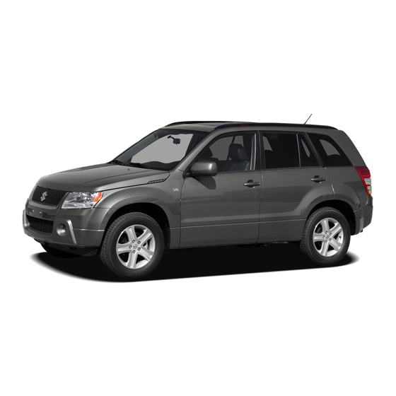
- Page 2 This owner’s manual applies to the GRAND VITARA series. 79K092 NOTE: The illustrated model is one of the GRAND VITARA series. © COPYRIGHT SUZUKI MOTOR CORPORATION 2008 78KS0-37E...
- Page 3 Please read this manual carefully WARNING, CAUTION and NOTE have tion in this manual and your vehicle. before operating your new SUZUKI and special meanings. These special mean- SUZUKI MOTOR CORPORATION review the manual from time to time.
- Page 4 CB (Citizen’s Band) radios may cause electronic interfer- ence with your vehicle’s ignition sys- tem, resulting in vehicle performance problems. Consult your SUZUKI dealer or qualified service technician for advice on installing such mobile communication equipment. 78KS0-37E...
- Page 5 INTRODUCTION Thank you for choosing SUZUKI and welcome to our growing family. Your choice was a wise one; SUZUKI products are a great value that will give you years of driving pleasure. This Owner’s Manual was prepared to help you have a safe, enjoyable, and trouble-free experience with your SUZUKI. In it you will learn about the vehicle’s operation, its safety features and maintenance requirements.
- Page 6 A wide variety of non-genuine replacement parts and accessories for SUZUKI vehicles are currently available in the market. Using these parts and accessories can affect the vehicle performance and shorten its useful life. Therefore, installation of non-genuine SUZUKI parts and accessories is not covered under warranty.
- Page 7 SERVICE STATION GUIDE 1. Fuel (see section 1) 2. Engine hood (see section 5) 3. Tire changing tools (see section 8) 4. Engine oil dipstick <Yellow> (see section 7) (RHD) 5. Automatic transmission fluid dipstick <Red> (see section 7) 6. Engine coolant (see section 7) (RHD) 7.
- Page 8 MEMO 78KS0-37E...
-
Page 9: Table Of Contents
TABLE OF CONTENTS FUEL RECOMMENDATION BEFORE DRIVING OPERATING YOUR VEHICLE DRIVING TIPS OTHER CONTROLS AND EQUIPMENT VEHICLE LOADING AND TOWING INSPECTION AND MAINTENANCE EMERGENCY SERVICE APPEARANCE CARE GENERAL INFORMATION SPECIFICATIONS INDEX 78KS0-37E... - Page 10 ILLUSTRATED TABLE OF CONTENTS EXTERIOR EXAMPLE 1. Rear Window Wiper (P.2-68) 2. Engine Hood (P.5-50) 3. Windshield Wiper (P.2-66) 4. Roof Rails or Roof Rack Anchors (if equipped) (P.5-66) 5. Radio Antenna (P.5-8) 6. Spare Wheel (P.8-3) 7. Tailgate (P.2-4) 8.
- Page 11 ILLUSTRATED TABLE OF CONTENTS INTERIOR EXAMPLE 1. Interior Light (P.5-51, P.7-35) 2. Seat Belts (P.2-22) 3. Coat hooks (if equipped) (P.5-58) 4. Side Curtain Air Bags (if equipped) (P.2-40) 5. Sun Visor (P.5-51) 6. Eyeglasses Holder (if equipped) (P.5-58) 7. Spot Light (P.5-53, P.7-35) 8.
- Page 12 ILLUSTRATED TABLE OF CONTENTS INSTRUMENT PANEL EXAMPLE 1. Electric Window Controls (if equipped) (P.2-12) 2. Electric Mirror Control (if equipped) (P.2-14) 3. Remote Audio Controls (if equipped) (P.5-26, P.5-47) 4. Front Air Bags (P.2-38) 5. Cruise Control (if equipped) (P.3-29) 6.
- Page 13 ILLUSTRATED TABLE OF CONTENTS INSTRUMENT PANEL EXAMPLE 1. Lighting Control Lever (P.2-63)/ Turn Signal Control Lever (P.2-65) 2. Instrument Cluster (P.2-44) 3. Windshield Wiper and Washer Lever (P.2-66)/Rear Window Wiper and Washer Switch (P.2-68) 4. Heated Rear Window and Heated Outside Rearview Mirrors Switch (if equipped) (P.2-69) 5.
- Page 14 ILLUSTRATED TABLE OF CONTENTS MEMO 78KS0-37E...
- Page 15 FUEL RECOMMENDATION FUEL RECOMMENDATION Fuel Recommendation ............1-1 65D394 78KS0-37E...
- Page 16 64J020 less than 350 ppm (parts per million). You responsibility of SUZUKI and may not be If your vehicle is not fitted with a restrictor should use the diesel fuel conformable to covered under the New Vehicle Warranty.
- Page 17 FUEL RECOMMENDATION CAUTION The fuel tank has an air space to allow for fuel expansion in hot weather. If you continue to add fuel after the filler nozzle has automati- cally shut off or an initial blowback occurs, the air chamber will become full.
- Page 18 FUEL RECOMMENDATION MEMO 78KS0-37E...
-
Page 19: Before Driving
BEFORE DRIVING BEFORE DRIVING Keys ..................2-1 Door Locks ................2-2 Keyless Start System Remote Controller/Keyless Entry System Transmitter ............. 2-5 Theft Deterrent Light ............2-11 Windows ................2-12 Mirrors .................. 2-13 Front Seats ................2-15 Rear Seats ................2-18 Seat Belts and Child Restraint Systems ...... - Page 20 A key made by an NOTE: • If you lose your immobilizer ignition key, ordinary locksmith will not work. see your SUZUKI dealer as soon as pos- 62J098 For gasoline engine model sible to have the lost one deactivated, Your vehicle comes with a pair of identical then have the new key made by them.
- Page 21 Keys: 8 BEFORE DRIVING Door Locks CAUTION Side Door Locks UNLOCK LOCK The immobilizer key is a sensitive electronic instrument. To avoid dam- aging the immobilizer key: • Do not expose it to impacts, mois- UNLOCK ture or high temperature such as on the dashboard under direct sun- LOCK light.
- Page 22 Spare Tire Nut Lock: 5 Door Locks: 3, 5, 8 BEFORE DRIVING Central Door Locking System passenger’s door lock) and turn the top of (if equipped) the key toward the rear of the vehicle twice. EXAMPLE To unlock the driver’s door (or the front passenger’s door) only, insert the key in that door lock and turn the top of the key UNLOCK...
- Page 23 Door Locks: 3, 5, 8 BEFORE DRIVING Child-Proof Locks Tailgate If you can not unlock the tailgate due to a You can lock or unlock the tailgate by using discharged battery or malfunction, follow the key in the driver’s door lock. the procedures below to unlock the tailgate from inside the vehicle.
-
Page 24: Operating Your Vehicle
The transmitter has only a keyless After using the emergency lever, be sure to entry system. For details, refer to the fol- see your SUZUKI dealer. lowing explanations. 62J010 (1) “LOCK” button (2) “UNLOCK”... - Page 25 • If you lose one of the remote controllers, two, then push the “UNLOCK” button (2) To unlock a door or all doors: ask your SUZUKI dealer as soon as pos- a second time. If you “double-click” too • Push the request switch on the door sible for a replacement.
- Page 26 The remote controller is a sensitive • If you lose one of the remote controllers, electronic instrument. To avoid dam- ask your SUZUKI dealer as soon as pos- When the remote controller is within aging the remote controller: sible for a replacement. Be sure to have approximately 80 cm (2 1/2 feet) from a •...
- Page 27 Door Locks: 3, 5, 8 BEFORE DRIVING Reminder function • If you open the driver’s door and lock the door by turning the lock knob forward or pushing the power door locking switch, the driver’s door will be automatically unlocked. •...
- Page 28 Door Locks: 3, 5, 8 BEFORE DRIVING Replacement of the battery If the remote controller becomes unreli- CAUTION able, replace the battery. The remote controller is a sensitive To replace the battery of the remote con- electronic instrument. To avoid dam- troller: aging it, do not expose it to dust or moisture or tamper with internal...
- Page 29 • To unlock other doors, wait a second or • If you lose one of the transmitters, ask two, then push the “UNLOCK” button (2) your SUZUKI dealer as soon as possible a second time. If you “double-click” too for a replacement. Be sure to have your fast, the doors will not unlock.
- Page 30 Door Locks: 3, 5, 8 BEFORE DRIVING 2) Remove the transmitter (2). Theft Deterrent Light WARNING Swallowing a lithium battery may EXAMPLE cause serious internal injury. Do not allow anyone to swallow a lithium battery. Keep lithium batteries away from children and pets. If swallowed, contact a physician immediately.
- Page 31 Door Locks: 3, 5, 8 BEFORE DRIVING Windows Passenger’s door EXAMPLE CLOSE Electric Window Controls (if equipped) The electric windows can only be operated when the ignition switch is in the “ON” posi- tion. Driver’s side OPEN EXAMPLE 81A009 64J012 To open a window, push the top part of the The passenger’s door has a switch (3) to switch and to close the window lift up the...
- Page 32 Door Locks: 3, 5, 8 Windows: 3, 8 BEFORE DRIVING Lock switch Mirrors WARNING EXAMPLE Inside Rearview Mirror • You should always lock the passen- ger’s window operation when there are children in the vehicle. Children can be seriously injured if they get part of their body caught by the window during operation.
- Page 33 Windows: 3, 8 BEFORE DRIVING Outside Rearview Mirrors Electric Mirrors (if equipped) WARNING • Always adjust the mirror with the selector set to the day position. • Only use the night position if it is necessary to reduce glare from the headlights of vehicles behind you.
- Page 34 Windows: 3, 8 Mirrors: 3, 8 BEFORE DRIVING view Mirrors (if equipped) Switch” in this Front Seats Adjusting Seat Position section. Seat Adjustment WARNING Never attempt to adjust the driver’s seat or seatback while driving. The seat or seatback could move unex- pectedly, causing loss of control.
- Page 35 Mirrors: 3, 8 BEFORE DRIVING Adjusting Seatbacks Adjustable Head Restraints (if equipped) WARNING All seatbacks should always be in an upright position when driving, or seat belt effectiveness may be reduced. Seat belts are designed to offer maxi- mum protection when seatbacks are in the upright position.
- Page 36 Seat Adjustment: 3 BEFORE DRIVING Front Seat Heater (if equipped) EXAMPLE EXAMPLE 78K035 79K036 78K018 To raise the front head restraint, pull To reinstall the head restraint, insert the upward on the restraint until it clicks. To head restraint bars into the holes (2) and With the ignition switch in the “ON”...
- Page 37 Seat Adjustment: 3 BEFORE DRIVING Rear Seats CAUTION Seat Adjustment To avoid damaging the heater ele- ment: WARNING • Do not subject the front seats to heavy impacts, such as children To avoid excessive seat belt slack, jumping on them. which reduces the effectiveness of •...
- Page 38 Seat Adjustment: 3 Adjustable Head Restraints: 3 BEFORE DRIVING Adjustable Head Restraints (if equipped) EXAMPLE Head restraints are designed to help reduce the risk of neck injuries in the case of an accident. Adjust the head restraint to the position which places the center of the head restraint closest to the top of your ears.
- Page 39 Adjustable Head Restraints: 3 BEFORE DRIVING Folding Rear Seats 3) Lower the adjustable head restraint The rear seat(s) of your vehicle can be fully. folded forward to provide additional cargo space. To fold the rear seats forward: 1) Remove the luggage compartment cover.
- Page 40 Seat Belts and Child Restraint Systems: 3 BEFORE DRIVING WARNING Luggage or other cargo should be stowed in the luggage compartment with the rear seat in an upright posi- tion, whenever possible. If you need to carry cargo in the passenger com- partment with the rear seat back folded forward, be sure to secure the cargo or it may be thrown about,...
- Page 41 Seat Belts and Child Restraint Systems: 3 BEFORE DRIVING Seat Belts and Child Restraint CAUTION Systems • When returning the rear seat cush- ion to the normal position, make sure that there is nothing around the striker. Any foreign materials prevent the seat cushion from being locked securely.
- Page 42 Seat Belts and Child Restraint Systems: 3 BEFORE DRIVING as low as possible across the hips Above the pelvis Across the pelvis 65D606 65D201 65D199 WARNING WARNING WARNING • Never allow persons to ride in the (Continued) (Continued) cargo area of a vehicle. In the event •...
- Page 43 Seat Belts and Child Restraint Systems: 3 BEFORE DRIVING Lap-Shoulder Belt WARNING WARNING Emergency Locking Retractor (ELR) (Continued) (Continued) The lap-shoulder belt has an emergency • Never use the same seat belt on • Avoid contamination of seat belt locking retractor (ELR), which is designed more than one occupant and never webbing by polishes, oils, chemi- to lock the seat belt only during a sudden...
- Page 44 Seat Belts and Child Restraint Systems: 3 BEFORE DRIVING Safety reminder by pulling the shoulder portion of the belt upward through the latch plate. The length of the diagonal shoulder strap adjusts itself Sit up straight and fully back to allow freedom of movement. Low on hips 60A036 60A038...
- Page 45 Seat Belts and Child Restraint Systems: 3 BEFORE DRIVING Driver’s Seat Belt Reminder EXAMPLE EXAMPLE 60A039 64J024 78K028 To unfasten the belt, push the red NOTE: “PRESS” button on the buckle and allow To identify the rear center lap-shoulder belt When the driver doesn’t buckle his or her the belt to retract.
- Page 46 Seat Belts and Child Restraint Systems: 3 BEFORE DRIVING Shoulder Anchor Height Adjuster Seat Belt Inspection Child Restraint Systems (if equipped) EXAMPLE EXAMPLE 65D209S 60G332S 64J198 Periodically inspect the seat belts to make Infant restraint - rear seat only Adjust the shoulder anchor height so that sure they work properly and are not dam- aged.
- Page 47 Seat Belts and Child Restraint Systems: 3 BEFORE DRIVING Child restraint SUZUKI highly recommends that you use a child restraint system to restrain infants EXAMPLE and small children. Many different types of child restraint systems are available; make sure that the restraint system you select meets applicable safety standards.
- Page 48 Seat Belts and Child Restraint Systems: 3 BEFORE DRIVING Installation with Lap-Shoulder Seat WARNING Belts Children could be endangered in a NOTE: crash if their child restraints are not There are two types of lap-shoulder belts properly secured in the vehicle. depending on the vehicle’s specification, When installing a child restraint sys- A-ELR...
- Page 49 Seat Belts and Child Restraint Systems: 3 BEFORE DRIVING A-ELR type belt A-ELR type CAUTION EXAMPLE EXAMPLE Before installing a child restraint sys- tem in the rear seat, raise the head restraint to the most upper position. ELR type belt EXAMPLE 83E035 83E031...
- Page 50 Seat Belts and Child Restraint Systems: 3 BEFORE DRIVING A-ELR type A-ELR type A-ELR type EXAMPLE EXAMPLE EXAMPLE 83E032 83E036 65D234 2) Allow the extra webbing to retract, and 3) Make sure that the retractor has con- A-ELR type pull the webbing toward the retractor to verted to the ALR mode by trying to pull EXAMPLE take up any slack.
- Page 51 Seat Belts and Child Restraint Systems: 3 BEFORE DRIVING A-ELR type (to revert from ALR to ELR) Installation with ISO-FIX Type Install a ISO-FIX type child restraint sys- Anchorages (if equipped) tem according to the instructions provided EXAMPLE by the child restraint system manufacturer. After installing the child restraint system, try moving it in all directions especially for- ward, to make sure the connecting bars...
- Page 52 Seat Belts and Child Restraint Systems: 3 BEFORE DRIVING Here is a general installation: 1) Pull upward on the rear head restraint EXAMPLE EXAMPLE to the most upper position. CAUTION Before installing a child restraint sys- tem in the rear seat, raise the head restraint to the most upper position.
- Page 53 Seat Belts and Child Restraint Systems: 3 BEFORE DRIVING Installation of Child Restraint with directly behind the child restraint. Do Top Strap (if equipped) not attach the top strap to the luggage EXAMPLE restraint loops (if equipped). EXAMPLE WARNING Front Do not attach the child restraint top strap to the luggage restraint loops (if equipped).
- Page 54 WARNING ens the seat belt so the belt fits the occu- This section of the owner’s manual pant’s body more snugly in the event of a describes your SUZUKI’s SEAT BELT frontal crash. The retractors will remain PRETENSIONER SYSTEM. Please...
- Page 55 SUZUKI. tensioner system serviced by an autho- Do not touch pretensioner system compo- rized SUZUKI dealer as soon as possible. nents or wiring. The wires are wrapped If the “AIR BAG” light on the instrument...
- Page 56 “AIR BAG” light stays on, or comes 64J031 on while driving, the air bag system (or the seat belt pretensioner system equipped)) may not work properly. Have the air bag system inspected by an autho- rized SUZUKI dealer as soon as possible. 2-37 78KS0-37E...
- Page 57 Supplemental Restraint System (air bags): 3, 9, 12 BEFORE DRIVING Front Air Bags dashboard. The words “SRS AIRBAG” are Front air bags will not inflate molded into the air bag covers to identify the location of the air bags. EXAMPLE Frontal collision range 65D236 63J259...
- Page 58 Supplemental Restraint System (air bags): 3, 9, 12 BEFORE DRIVING dents. Remember, since an air bag Air bag symbol deploys only one time during an accident, seat belts are needed to restrain occu- EXAMPLE pants from further movements during the WARNING AVERTISSEMENT accident.
- Page 59 Supplemental Restraint System (air bags): 3, 9, 12 BEFORE DRIVING Side Air Bags and Side Curtain Air molded into the side air bag cover to iden- Side collision range Bags (if equipped) tify the location of the side air bags. WARNING EXAMPLE If your vehicle is equipped with a side...
- Page 60 Supplemental Restraint System (air bags): 3, 9, 12 BEFORE DRIVING Side air bags and side curtain air bags lisions, rollovers or minor side collisions, How the system works will not inflate since they would offer no protection in In a frontal collision, the crash sensors will those types of accidents.
- Page 61 BEFORE DRIVING A seat belt helps keep you in the proper position for maximum protection when an WARNING air bag inflates. Adjust your seat as far • The driver should not lean over the back as possible while still maintaining steering wheel.
- Page 62 If this hap- pens, have the air bag system inspected do not place any cup holders or by the SUZUKI dealer as soon as possible. other objects on the door, as these objects could be propelled by the Special procedures are required for servic- air bag in the event of a crash.
- Page 63 BEFORE DRIVING Instrument Cluster EXAMPLE 1. Speedometer 2. Tachometer 3. Fuel gauge 4. Temperature gauge 5. Information display 6. MODE/ILL knob 7. TRIP knob 8. Warning and indicator lights 78K090 2-44 78KS0-37E...
- Page 64 ABS. your SUZUKI dealer to inspect the The light also comes on when the fluid in brake system. If this happens: the brake fluid reservoir falls below the •...
- Page 65 ® If one of these happens, have the system thing wrong with the ESP systems (other inspected by your SUZUKI dealer. than ABS). You should have the system If the ABS becomes inoperative, the brake inspected by an authorized SUZUKI system will function as an ordinary brake dealer.
- Page 66 ® Hill descent control Indicator Light the ESP system. Have your vehicle inspected by an authorized SUZUKI When the “ESP OFF” switch is pushed to ® dealer. turn off the ESP systems (other than ABS), the “ESP OFF”...
- Page 67 If there is enough oil, the lubrication sys- SUZUKI dealer. The light will come on and stay on if there tem should be inspected by your SUZUKI is a problem in the air bag system or the dealer before you drive the vehicle again.
- Page 68 “ON” position, this light comes on to let you Bring the vehicle to your SUZUKI dealer to comes on. know the light is working. If this light blinks have the problem corrected.
- Page 69 If this light comes on and the engine is NANCE” section. automatically turned off, it indicates that the injection system has a fault. Bring the vehicle to your SUZUKI dealer as soon as possible. 81A208 This light comes on for several seconds when the ignition switch is turned to the “ON”...
- Page 70 BEFORE DRIVING ® Diesel Particulate Filter (DPF Open Door Warning Light “SET” Indicator Light (if equipped) Warning Light (For Diesel Engine Model) (if equipped) 54G391 65D474 This light remains on until all doors are When the vehicle’s speed is controlled by 64J244 completely closed.
- Page 71 BEFORE DRIVING Transmission Warning Light tem. Bring the vehicle to your SUZUKI Turn Signal Indicators (if equipped) dealer to have the problem corrected. Keyless Start System Indicator Light (if equipped) 50G055 81A262 When you turn on the left or right turn sig-...
- Page 72 (if equipped) should have your vehicle inspected by an authorized SUZUKI dealer. NOTE: The information display shows the warning and indicator message when the transfer system is operated, or has a problem.
- Page 73 BEFORE DRIVING Speedometer Tachometer (if equipped) Fuel Gauge EXAMPLE EXAMPLE 78K038 78K039 64J052 The speedometer indicates vehicle speed The tachometer indicates engine speed in This gauge gives an approximate indica- in km/h and/or mph. revolutions per minute. tion of the amount of fuel in the fuel tank. “F”...
- Page 74 BEFORE DRIVING NOTE: Temperature Gauge Illumination Control The information display shows the warning and indicator message when this light comes on. NOTE: The activation point of the low fuel warning light (1) varies depending on road condi- tions (for example, slope or curve) and driving conditions because of fuel moving in the tank.
- Page 75 BEFORE DRIVING Information Display The information display shows the follow- ing information. EXAMPLE (if equipped) The information display is shown when the Display (A) ignition switch is in the “ON” position. A/T selector position indicator (for auto- matic transmission) Display (B) 79K062 Warning and Indicator Messages/Fuel NOTE:...
- Page 76 BEFORE DRIVING A/T Selector Position To switch the display indication, push the (for automatic transmission) MODE/ILL knob (2) quickly. EXAMPLE NOTE: EXAMPLE The value of fuel consumption, driving range and average speed shown in the dis- play are affected by conditions such as the following;...
- Page 77 BEFORE DRIVING NOTE: Driving range Average Speed When you reconnect the negative (–) ter- If you selected driving range the last time If you selected average speed the last time minal to the battery, the value of average you drove the vehicle, the display indicates you drove the vehicle, the display indicates fuel consumption will be shown after driv- “---”...
- Page 78 BEFORE DRIVING Odometer/Trip meter/Thermometer NOTE: When the ignition switch is turned to the CAUTION The outside temperature indication is not “ON” position, the display (C) shows one of the actual outside temperature when driv- Keep track of your odometer reading the following three indications, trip meter A, ing at low speed, or when stopped.
- Page 79 BEFORE DRIVING Fuel economy units Master warning indicator You can change the units that fuel con- EXAMPLE sumption is displayed in. Language You can change the language of the infor- mation display. 79K069 Avg. fuel economy reset 78K049 NOTE: You can change when the value of average Current settings appear with reversed text When the display shows warning and indi- fuel consumption is reset.
- Page 80 79K070 ® Blinks Ding There may be a problem with the ESP system. Have your vehicle inspected by an authorized SUZUKI dealer. 79K071 Blinks Ding There may be problem with the hill descent control sys- tem and the hill hold control system.
- Page 81 Master Warning Sound Cause and Remedy message Indicator Blinks There may be a problem with the 4WD system. Have your vehicle inspected by an authorized SUZUKI dealer. 79K074 Ding Fuel is low. (#1) Fill the fuel tank immediately. 79K075 The outside temperature is near freezing. The road may be icy.
- Page 82 BEFORE DRIVING Lighting Control Lever Lighting Operation HIGH PASS 79K101 79K100 With the headlights on, push the lever for- 65D611 ward to switch to the high beams (main To turn the lights on or off, twist the knob beam) or pull the lever toward you to on the end of the lever.
- Page 83 BEFORE DRIVING Lights “On” reminder (if equipped) Front Fog Light Switch Headlight Leveling Switch A buzzer sounds to remind you to turn off (if equipped) (if equipped) the lights if they are left on when the igni- tion key is removed and the driver’s door is opened.
- Page 84 BEFORE DRIVING Head Light Washer Switch Turn Signal Control Lever Switch (if equipped) Vehicle Load Condition Position Driver only Driver + 1 passenger (in front seat) Driver + full passengers, No cargo Driver + full passengers, Cargo added Driver + Cargo (full load) 65D611 64J059 WARNING...
- Page 85 BEFORE DRIVING Turn Signal Operation Hazard Warning Switch Windshield Wiper and Washer With the ignition switch in the “ON” posi- Lever tion, move the lever up or down to activate the right or left turn signals. 64J054 Push in the hazard warning switch to acti- vate the hazard warning lights.
- Page 86 BEFORE DRIVING Windshield Wipers Windshield Washer EXAMPLE EXAMPLE EXAMPLE MIST 63J302 63J301 63J303 If the lever is equipped with the “INT TIME” control, turn the control forward or rear- To turn the windshield wipers on, move the To spray windshield washer fluid, pull the ward to adjust the intermittent wiper opera- lever down to one of the three operating lever toward you.
- Page 87 BEFORE DRIVING Rear Window Wiper/Washer Switch Tilt Steering Lock Lever CAUTION (if equipped) (if equipped) To help prevent damage to the wind- EXAMPLE shield wiper and washer system Washer UNLOCK components, you should take the fol- Wiper lowing precautions: • Do not continue to hold in the lever when there windshield...
- Page 88 BEFORE DRIVING 1) Pull up the lock lever to unlock the Horn Heated Rear Window and steering column. Heated Outside Rearview 2) Adjust the steering wheel to the desired EXAMPLE Mirrors (if equipped) Switch height and lock the steering column by pulling down the lock lever.
- Page 89 BEFORE DRIVING An indicator light will be lit when the defroster is on. The defroster will only work when the engine is running. To turn off the defroster, push the switch (1) again. CAUTION The heated rear window and the heated outside rearview mirrors (if equipped) use a large amount of elec- tricity.
- Page 90 BEFORE DRIVING MEMO 2-71 78KS0-37E...
- Page 91 OPERATING YOUR VEHICLE OPERATING YOUR VEHICLE Exhaust Gas Warning ............3-1 Daily Inspection Checklist ..........3-2 Engine Oil Consumption ............ 3-3 Ignition Switch ..............3-3 Parking Brake Lever ............3-7 Pedal ..................3-9 Starting the Engine ............. 3-10 Using the Transmission ............. 3-12 Using the Transfer Switch (if equipped) ......
- Page 92 Exhaust Gas Warning: NO OPERATING YOUR VEHICLE Exhaust Gas Warning WARNING WARNING (Continued) (Continued) • Do not park with the engine run- • Have the exhaust system inspected ning for a long period of time, even periodically for damage and leaks. in an open area.
- Page 93 Daily Inspection Checklist: NO OPERATING YOUR VEHICLE Daily Inspection Checklist 4) Make sure the hood is fully closed and ing for proper latch operation. See the latched. item “All Latches, Hinges & Locks” of Before Driving “CHASSIS AND BODY” in the “Periodic 5) Check the headlights, turn signal lights, brake lights and horn for proper opera- Maintenance...
- Page 94 Engine Oil Consumption: Starting the Engine: 1 OPERATING YOUR VEHICLE Engine Oil Consumption making it appear that the oil level has not Ignition Switch changed. It is normal for the engine to consume You should also be aware that the diluting some engine oil during normal vehicle ingredients evaporate out when the vehicle operation.
- Page 95 Starting the Engine: 1 OPERATING YOUR VEHICLE Vehicle Without Keyless Start Sys- Manual transmission Accessories such as the radio can oper- ate, but the engine is off. EXAMPLE This is the normal operating position. All electrical systems are on. Push START This is the position for starting the engine using the starter motor.
- Page 96 Starting the Engine: 1 OPERATING YOUR VEHICLE Vehicle With Keyless Start System of the remote controller may be unreli- able. NOTE: • If the battery of the remote controller runs down or there are strong radio waves or noise, the operating range may be narrower or the remote controller may be inoperative.
- Page 97 Using the Transmission: 10 OPERATING YOUR VEHICLE switch to “START”. If the engine does not ACC (2) start, close all doors completely or turn the Accessories such as the radio can oper- ate, but the engine is off. ignition switch back to the “LOCK” position, then start the engine.
- Page 98 SUZUKI dealer. windows or power sunroof. They • Do not leave the ignition switch in also could suffer from heat stroke the “ON” position if the engine is in warm or hot weather. These...
- Page 99 • If the parking brake does not hold the vehicle securely or does not fully release, have your vehicle inspected immediately by an autho- rized SUZUKI dealer. 78KS0-37E...
- Page 100 64J082 Brake Pedal (2) Automatic transmission Your SUZUKI vehicle is equipped with either front and rear disc brakes or front disc brakes and rear drum brakes. Depressing the brake pedal applies both sets of brakes.
- Page 101 Using the Transfer Switch: 10 OPERATING YOUR VEHICLE Starting the Engine Starting a Cold and Warm Engine WARNING (For Gasoline Engine Model) Before Starting the Engine With your foot off the accelerator pedal, Make sure that the parking brake is crank the engine by turning the ignition key set fully and the transmission is in to “START”.
- Page 102 ® is regenerating, the exhaust the third trial failed, consult autho- gas temperature could be higher. rized SUZUKI dealer. • If the engine is started after long NOTE: time parking at extremely cold When you drive your vehicle, white smoke...
- Page 103 Using the Transfer Switch: 10 OPERATING YOUR VEHICLE ® warning light Using the Transmission EXAMPLE Manual Transmission 64J244 ® If the DPF warning light comes on when ® driving, the DPF is nearly clogged. You ® should regenerate the DPF when the ®...
- Page 104 Using the Transfer Switch: 10 OPERATING YOUR VEHICLE 5-Speed Automatic Transmission Power mode selector switch CAUTION EXAMPLE • To help avoid clutch damage, do not use the clutch pedal as a foot- rest while driving or use the clutch to keep the vehicle stationary on a hill.
- Page 105 Using the Transfer Switch: 10 OPERATING YOUR VEHICLE Slippery road mode Gearshift lever For all normal driving, make sure that the When the “A/T POWER” switch is on with “POWER” indicator light is off, then put the shift in “3” (Low 2) position, the gear will be gearshift lever into “D”...
- Page 106 Using the Transfer Switch: 10 OPERATING YOUR VEHICLE D (Drive) NOTE: 4-Speed Automatic Transmission Use this position for all normal driving. If you move the gearshift lever to a lower gear while driving faster than the maximum EXAMPLE With the gearshift lever in “D” range you allowable speed for the lower gear, the can get an automatic downshift by press- transmission will not actually downshift...
- Page 107 Using the Transfer Switch: 10 OPERATING YOUR VEHICLE Power mode selector switch Slippery road mode Gearshift lever When the “A/T POWER” switch is on with shift in “2” (Low 2) position, the gear will be fixed in second while driving or when start driving.
- Page 108 Braking: 6 OPERATING YOUR VEHICLE For all normal driving, make sure that the D (Drive) NOTE: “POWER” indicator light is off, then put the Use this position for all normal driving. If you move the gearshift lever to a lower gear while driving faster than the maximum gearshift lever into “D”...
- Page 109 Braking: 6 OPERATING YOUR VEHICLE If You Can Not Shift Automatic 4) Remove the cover (1) on the hole. Using the Transfer Switch Transmission Gearshift Lever Out 5) With inserting the key or the flat end rod (if equipped) into the slot in the hole, shift the gear- of “P”...
- Page 110 Break-In: 6 Catalytic Converter: NO OPERATING YOUR VEHICLE (1) Front differential (2) Engine (3) Transmission (4) High/Low clutch (5) Transfer case (6) Center differential (7) Differential lock clutch (8) Chain (9) Rear propeller shaft (10) Rear differential (11) Front propeller shaft (10) (11) 64J143...
- Page 111 Catalytic Converter: NO Improving Fuel Economy: NO OPERATING YOUR VEHICLE Description of Transfer Switch Positions In this position, engine power is not sup- plied to the front or rear axles. Only use N (Neutral) this position for towing your vehicle. When you turn the transfer switch to the “N”...
- Page 112 Improving Fuel Economy: NO OPERATING YOUR VEHICLE 4H (4-wheel drive high range) In this position, engine power is supplied to the front and rear axles. Use this position for normal driving. 64J220 3-21 78KS0-37E...
- Page 113 OPERATING YOUR VEHICLE 4H LOCK (4-wheel drive high range center differential lock) In this position, engine power is supplied to the front and rear axles and you get better traction than when driving in “4H”. Use this position when you need better traction than “4H”...
- Page 114 OPERATING YOUR VEHICLE 4L LOCK (4-wheel drive low range center differential lock) In this position, engine power is supplied to the front and rear axles and you get better traction and more low-speed torque than when driving in “4H”. Use this position when you need better traction than “4H”...
- Page 115 OPERATING YOUR VEHICLE Transfer Switch Operation transfer switch. Be sure to wait until traf- NOTE: Operate the transfer switch according to fic conditions allow you to accelerate and • When shifting between the transfer appropriate procedure described decelerate safety before using this pro- switch position and the transfer gear below: cedure.
- Page 116 OPERATING YOUR VEHICLE tion for 5 seconds until the “N” indicator blinks, then turn the switch to the “N” posi- CAUTION CAUTION tion. • Be sure to stop the vehicle com- (Continued) When you turn the transfer switch to the pletely before operating the trans- •...
- Page 117 OPERATING YOUR VEHICLE The basic operation for transfer switch Current Position Current Indicator Target Position Target Indicator – – 4H LOCK – 4H LOCK 4L LOCK 4L LOCK 4H LOCK N: Neutral 4H: 4-wheel drive high range mode 4H LOCK: 4-wheel drive high range center differential lock mode 4L LOCK: 4-wheel drive low range center differential lock mode 3-26 78KS0-37E...
- Page 118 Operation ing Indicator In any position Blinks There may be a problem with the 4WD system. Have your vehicle inspected by an authorized SUZUKI dealer. 79K074 In “N” position Blinks Series of This message informs you that the Beeps transfer switch is in “N”, which is used only for towing your vehicle.
- Page 119 OPERATING YOUR VEHICLE Transfer Switch Master Warn- Warning and Indicator messages Sound Cause and Remedy Operation ing Indicator Switching between Beep (For automatic transmission) “4H LOCK” and The desired transfer gear has not been “4L LOCK” engaged. Switching between Release your foot from the accelerator “4H”...
- Page 120 OPERATING YOUR VEHICLE Cruise Control (if equipped) 52D113 When you push the “ON/OFF” switch, the system is on and a “CRUISE” indicator light on the instrument cluster will be on. 79K049 To Set Cruising Speed 79K032 Turn on the cruise control system by push- The cruise control system allows you to ing the “ON/OFF”...
- Page 121 OPERATING YOUR VEHICLE To reset the cruise control to a faster To “Resume” a Previously Set Braking speed, use either of the following proce- Speed dures: After canceling cruise control operation without turning off the “ON/OFF” switch • Hold in the “RES/ACC” switch (4). Vehi- (1), you can “resume”...
- Page 122 OPERATING YOUR VEHICLE NOTE: WARNING WARNING The ABS will not work if vehicle speed is under about 5 – 6 km/h (3 – 4 mph). If water gets into the brake drums, Even without reserve power in the brake performance may become poor brake system, you can still stop the WARNING and unpredictable.
- Page 123 1) Pull off the road and stop care- braking on a slippery road or when hard braking even on a dry paved fully. road. Ask your SUZUKI dealer to 2) Turn the ignition switch to “LOCK” inspect the ABS system immediately. and then start the engine again.
- Page 124 OPERATING YOUR VEHICLE ® Electronic Stability Program The ESP has the following three systems: Anti-Lock Braking System (ABS) ABS will help you avoid skidding by elec- ® (ESP ) (if equipped) Stability Control System tronically controlling braking pressure. It ® is a registered trademark of Daimler The vehicle stability control system helps will also help you maintain steering control...
- Page 125 (other than ABS). You should ® • The ESP may not work properly if have the systems inspected by an engine related parts such as the authorized SUZUKI dealer. 66J031 muffler are not equivalent to stan- ® When the ESP systems (other than ABS)
- Page 126 ® be a malfunction of the ESP sys- tems (other than ABS). You should have the systems inspected by an authorized SUZUKI dealer. 66J032 ® You should turn the ESP on during your NOTE: ordinary driving, so that you have the ben- When the “ESP”...
- Page 127 OPERATING YOUR VEHICLE ® systems (other than ABS) will be Hill descent control System canceled to provide improved vehicle (if equipped) traction, and the “ESP OFF” indicator The hill descent control system is designed light will come on. to reduce the driver’s workload when going When the transfer switch (if equipped) is down steep, rough and/or slippery hills turned to the “4L LOCK”...
- Page 128 OPERATING YOUR VEHICLE Hill descent control switch approximately 5 km/h (3 mph) when going NOTE: down a hill. You may hear a sound coming from the The brake/tail lights come on and the slip engine when the hill descent control sys- indicator light blinks while the hill descent tem is activated.
- Page 129 Have your vehicle You may hear a sound coming from the hill, the system helps to prevent the vehicle inspected by an authorized SUZUKI engine when the hill hold control system is from rolling downward while you move your dealer.
- Page 130 OPERATING YOUR VEHICLE MEMO 3-39 78KS0-37E...
- Page 131 DRIVING TIPS DRIVING TIPS Important Vehicle Design Features to Know ....4-1 Break-In ................4-2 Catalytic Converter (if equipped) ........4-3 Improving Fuel Economy ........... 4-4 On-Paved Road Driving ............4-4 Off-Road Driving ..............4-6 60G409 78KS0-37E...
- Page 132 • Never drive while under the influ- Multipurpose vehicles such as your new ence of alcohol or other drugs. SUZUKI have higher ground clearance and 65D231S Alcohol and drugs can seriously a narrower track than conventional passen- impair your ability to drive safely,...
- Page 133 Important Vehicle Design Features to Know: NO On-Paved Road Driving: NO DRIVING TIPS In a rollover crash, an unbelted person is Narrower Body Width and Track Break-In significantly more likely to die than a per- Your vehicle is narrower than the average passenger car so that it can pass through son wearing a seat belt.
- Page 134 On-Paved Road Driving: NO DRIVING TIPS Catalytic Converter damage to the catalyst and other vehicle components. (if equipped) CAUTION EXAMPLE To minimize the possibility of cata- lyst or other vehicle damage: • Maintain the engine in the proper operating condition. •...
- Page 135 On-Paved Road Driving: NO Off-Road Driving: NO DRIVING TIPS Improving Fuel Economy Keep the air cleaner clean On-Paved Road Driving The following instructions will help you The data of accidents show that most roll- EXAMPLE improve fuel economy. over accidents for multi-purpose vehicles are caused when a driver loses control of Avoid excessive idling the vehicle and leaves the paved portion of...
- Page 136 Off-Road Driving: NO DRIVING TIPS All Types of Rollover Accidents relative to conventional passenger cars. As with many kinds of automobile acci- Remember, small multipurpose vehicles CAUTION have more responsive steering and a dents, rollovers can be greatly reduced by Do not operate your vehicle in “4H doing what all prudent drivers should do, higher center of gravity than conventional...
- Page 137 Whenever possible, avoid traction, observe the following precautions: this potential hazard. Also, if you have to • Use SUZUKI genuine tire chains or exit your vehicle on a side-hill, always get equivalent small link chain or wire chain.
- Page 138 DRIVING TIPS • Install the chains on the rear tires. Do not drive through deep or rushing • With the chains on, drive only at slow WARNING water and moderate speeds. Driving in deep or rushing water can be • Do not allow anyone to stand near hazardous.
- Page 139 “Tires” in the “INSPECTION AND inspected your authorized MAINTENANCE” section SUZUKI dealer as soon as possi- details. ble. • Do not use tires other than those specified by SUZUKI. Never use dif- ferent sizes or types of tires on the front and rear wheels.
- Page 140 DRIVING TIPS MEMO 78KS0-37E...
-
Page 141: Other Controls And Equipment
OTHER CONTROLS AND EQUIPMENT OTHER CONTROLS AND EQUIPMENT Automatic Heating and Air Conditioning System (Climate Control) ..............5-1 Radio Antenna (if equipped) ..........5-8 Audio Systems (type A) ............5-8 Audio Systems (type B) ............5-32 Fuel Filler Cap ..............5-49 Engine Hood ................ - Page 142 Parking Brake Lever: 6 OTHER CONTROLS AND EQUIPMENT Automatic Heating and Air Conditioning System 1. Windshield defroster outlet 2. Side defroster outlet (Climate Control) 3. Side outlet 4. Center outlet Air Outlet 5. Floor outlet EXAMPLE Center outlet EXAMPLE Open Close 64J199 66J250...
- Page 143 Pedal: 6 OTHER CONTROLS AND EQUIPMENT Side outlet Description of Controls 78K023 (1) Temperature selector (2) Blower speed selector (3) Air intake selector (4) Air flow selector (5) Defrost switch 63J045 (6) “OFF” switch (7) “AUTO” switch When “Open”, air comes out from the side (8) Air conditioning switch outlets regardless of the air flow selector (9) LCD display...
- Page 144 Gearshift Lever: 10 Fuel Filler Cap: 5 OTHER CONTROLS AND EQUIPMENT Temperature selector (1) Air conditioning switch (8) Blower speed selector (2) A/C: OFF A/C: ON 78K047 78K024 78K048 Turn the temperature selector (1) to adjust The air conditioning switch (8) is used to The blower speed selector (2) is used to the temperature.
- Page 145 Fuel Filler Cap: 5 OTHER CONTROLS AND EQUIPMENT Air intake selector (3) “FRESH AIR” and “RECIRCULATED AIR” Air flow selector (4) are selected alternately each time the air intake selector is pushed. NOTE: If you select “RECIRCULATED AIR” for an extended period of time, the air in the vehi- cle can become contaminated.
- Page 146 Folding Rear Seat: 3 OTHER CONTROLS AND EQUIPMENT Ventilation (c) Heat (e) Defrost switch (5) 64J069 64J071 Temperature-controlled air comes out of Temperature-controlled air comes out of the center and side air outlets. the floor outlets and the side outlets, a small amount of air comes out of the wind- Bi-level (d) shield defroster outlets and the side...
- Page 147 You should Temperature-controlled air comes out of have the system inspected by an autho- the windshield defroster outlets, the side rized SUZUKI dealer. defroster outlets and the side outlets. NOTE: NOTE: • To find the temperature at which you are When the defrost switch (5) is pushed to most comfortable, start with the 25°C...
-
Page 148: Inspection And Maintenance
Schedule” 64J074 “INSPECTION AND MAINTENANCE” sec- NOTE: tion. Have this job done by your SUZUKI If you need maximum defrosting: EXAMPLE dealer as the lower glove box must be low- • push the defrost switch (5) to turn on the ered for this job. - Page 149 Folding Rear Seat: 3 OTHER CONTROLS AND EQUIPMENT Radio Antenna (if equipped) Audio Systems (type A) Type 2 There are two types of audio system as shown below: Type 1 78K093 63J055 AM/FM 6-CD PLAYER The radio antenna is removable. To WITH CD CHANGER CONTROL remove the antenna, turn it counterclock- wise.
- Page 150 Even in the event that trouble arises, the compact disc never open the case, disassemble the unit, or lubricate the rotating parts. Please bring the unit to an authorized SUZUKI dealer or a Clarion service Department. 52D277 52D275 New discs may have some roughness To remove the compact disc from its stor- around the edges.
- Page 151 Folding Rear Seat: 3 Armrest: 3 OTHER CONTROLS AND EQUIPMENT NOTE: • Do not use commercially available CD protection sheets or discs equipped with stabilizers, etc. These may get caught in the internal mechanism and damage the disc. • CD-R discs may not be able to playback in this unit due to the recording condi- 52D348 52D350...
- Page 152 Armrest: 3 Sun Visor: 5 OTHER CONTROLS AND EQUIPMENT Basic Operations Display Type 1 AM/FM CD PLAYER WITH CD CHANGER CONTROL 79K086 (1) Power on/off knob Volume control knob (2) Tone/balance/fader control knob (3) Preset button 5 (4) Preset button 6 (5) Mute button (3) (4) (6) Clock button H...
- Page 153 Interior Light Switch: 7 OTHER CONTROLS AND EQUIPMENT Turning power on/off NOTE: Adjusting the AVC (Auto volume con- Press the power on/off knob (1). When the clock has not been set, the time trol) “12:00” will flash in the display. The unit starts in the function mode it was The Auto Volume Control (AVC) function in when the power was turned off last.
- Page 154 Spot Light: 7 Luggage Compartment Light: 7 OTHER CONTROLS AND EQUIPMENT Listening to the Radio Display Type 1 AM/FM CD PLAYER WITH CD CHANGER CONTROL 66J097 (1) Band switch button (FM/AM) (2) Seek up button (3) Seek down button (4) Manual tuning knob (5) Preset buttons (1 to 6) (6) Auto store button (AS) (7) Scan button (SCAN)
- Page 155 Front Seat Heater: 8 OTHER CONTROLS AND EQUIPMENT Selecting the reception band Auto store Scan tuning Press the band switch button (1). Press and hold the auto store button (6) for 1) Press the scan button (7). Stations are automatically sought for in Each time the button is pressed, the recep- 2 seconds or longer.
- Page 156 Assist Grips: 3 Coat Hooks: Sunroof: 5, 8 OTHER CONTROLS AND EQUIPMENT Radio Reception Listening to a CD Radio reception can be affected by envi- CAUTION ronment, atmospheric conditions, or radio • Never insert your finger or hand signal’s power and distance from the sta- into the CD insertion slot.
- Page 157 Sunroof: 5, 8 OTHER CONTROLS AND EQUIPMENT Type 1 Display AM/FM CD PLAYER WITH CD CHANGER CONTROL (Built in CD Player) 66J100 (1) CD insertion slot (2) CD eject button (3) Disc button (CD) (4) Track up button/Fast forward button (5) Track down button/Rewind button (6) Repeat button (RPT) (A) Mode indicator...
- Page 158 Sunroof: 5, 8 OTHER CONTROLS AND EQUIPMENT NOTE: Loading a CD Selecting a track About Single CDs (8 cm CDs) Insert a CD in the CD insertion slot (1). • Press the track up button (4) to listen to the next track. •...
- Page 159 Engine Hood: 5 OTHER CONTROLS AND EQUIPMENT Type 2 Display AM/FM 6-CD PLAYER WITH CD CHANGER CONTROL (Built-in CD Changer) 66J102 (1) Load button (LOAD) (2) Disc select buttons (1 to 6) (3) CD insertion slot (4) CD eject button (5) Disc button (CD) (6) Track up button/Fast forward button (7) Track down button/Rewind button...
- Page 160 Cup Holder and Storage Bin: 3 OTHER CONTROLS AND EQUIPMENT NOTE: Loading one CD Loading multiple CDs About Single CDs (8 cm CDs) 1) Press the load button (1), then press 1) Press the load button (1) for 2 seconds •...
- Page 161 Cup Holder and Storage Bin: 3 Eyeglasses Holder: OTHER CONTROLS AND EQUIPMENT Ejecting all the CDs Listening to a CD Repeat play Press the CD eject button (4) for 2 seconds 1) When a CD is inserted, it is automati- Press the repeat button (8).
- Page 162 Accessory Socket: 8 Cigarette Lighter and Ashtray: 3, 8 OTHER CONTROLS AND EQUIPMENT Listening to an MP3/WMA Disc Display (Type 1) Type 1 AM/FM CD PLAYER WITH CD CHANGER CONTROL 66J104 Display (Type 2) 66J105 (1) Sound control knob Type 2 AM/FM 6-CD PLAYER WITH CD CHANGER CONTROL (2) Repeat button (RPT) (3) Track up button/Fast forward button (4) Track down button/Rewind button...
- Page 163 Cigarette Lighter and Ashtray: 3, 8 Frame Hooks: 5, 6 OTHER CONTROLS AND EQUIPMENT What is MP3/WMA? • You may encounter trouble in playing MP3 (MPEG1/2 Audio Layer-III) and WMA • It is recommended to set the bit rate to MP3/WMA files or displaying the infor- “64 kbps or more”...
- Page 164 Tire Changing Tool: 3, 5 Shopping Hook: OTHER CONTROLS AND EQUIPMENT • Maximum number of files in one folder: NOTE: Fast forwarding/Rewinding a track This operation should be performed within • Hold in the fast forward button (3) to advance a track rapidly. •...
- Page 165 Shopping Hook: Front Seat Back Pocket: 3 Underseat Tray: 3 OTHER CONTROLS AND EQUIPMENT Listening to a CD from an External CD Changer (Option) Display Type 1 AM/FM CD PLAYER WITH CD CHANGER CONTROL (A) (B) 66J113 (1) Disc button (CD) (2) Disc select buttons (1 to 6) (3) Track up button/Fast forward button (4) Track down button/Rewind button...
- Page 166 Luggage Restraint Loops: 5 Luggage Compartment Cover: 5 OTHER CONTROLS AND EQUIPMENT Selecting a CD changer mode Selecting a disc Random play Press the disc button (1). Press the disc select button (2) corre- Press the scan button (6). Each time the button is pressed, the mode Each time the button is pressed, the sponding to the disc number you want to selected CD plays as follows:...
- Page 167 Luggage Compartment Cover: 5 Underfloor Bins: OTHER CONTROLS AND EQUIPMENT Repeat play Remote Audio Controls To control the volume: Press the repeat button (5). • To increase the volume, push the upper (if equipped) Each time the button is pressed, repeat part of the switch (1).
- Page 168 Roof Rails or Roof Rack Anchors: 5, 13 OTHER CONTROLS AND EQUIPMENT Anti-Theft Feature (1) Power on/off knob (2) Track up button/Fast forward button (3) Preset buttons (1 to 6) Type 1 AM/FM CD PLAYER WITH CD CHANGER CONTROL The anti-theft feature is intended to dis- courage theft or the audio system by pre- venting the system from operating when it is moved to a different vehicle.
- Page 169 OTHER CONTROLS AND EQUIPMENT NOTE: Canceling Your Established PIN Establish your PIN by combining numbers Setting EXAMPLE from 1 to 6 into any 4-digit number. If you This operation is to be done when you forget your PIN, when you remove the bat- want to cancel the anti-theft function or tery for repair etc., you will no longer be change your PIN.
- Page 170 OTHER CONTROLS AND EQUIPMENT Confirming Your Personal Identifi- registered PIN, the power of the audio cation Number (PIN) system will turn off, and you will be able EXAMPLE to operate the audio system. When the main power source is discon- nected such as when you exchange your NOTE: battery, etc, you will have to confirm your...
- Page 171 OTHER CONTROLS AND EQUIPMENT Troubleshooting Applicable to every device Phenomenon Cause Remedy Power is not turned on. Fuse is blown. Contact your authorized SUZUKI dealer. (No sound is produced) Connections are not properly made. Contact your authorized SUZUKI dealer. Radio Phenomenon Cause Remedy Too much noise.
- Page 172 CD/CD changer “Disc error”. The CD is inserted upside down or only an eight-centimeter CD adapter is equipped. Check disc for correct loading. If an error display not listed above appears, turn off the unit and contact your SUZUKI dealer. 5-31 78KS0-37E...
- Page 173 WITH CD CHANGER CONTROL unit, or lubricate the rotating parts. Please bring the unit to an authorized SUZUKI dealer or a Clarion service Department. 52D275 To remove the compact disc from its stor- age case, press down on the center of the case and lift the disc out, holding it care- fully by the edges.
- Page 174 OTHER CONTROLS AND EQUIPMENT Never touch the surface. 52D348 52D350 52D347 Never stick labels on the surface of the Do not use compact discs that have large To remove fingermarks and dust, use a compact disc or mark the surface with a scratches, are misshaped, or cracked, etc.
- Page 175 OTHER CONTROLS AND EQUIPMENT Listening to a CD General CAUTION • Never insert your finger or hand into the CD insertion slot. Never insert foreign objects. • Never insert a CD with glue coming out from adhesive tape or a rental CD label or with a trace indicating 52D274 that adhesive tape or a rental CD...
- Page 176 OTHER CONTROLS AND EQUIPMENT Power On/Off Audio Control (4): AVC OFF / AVC1 / AVC2 / AVC3 Press the power on/off knob (1) to switch Bass / Treble / Balance / Fader can be (5): AVC3 / AVC2 / AVC1 / AVC OFF power on.
- Page 177 OTHER CONTROLS AND EQUIPMENT Radio Radio Mode NOTE: If FM/AM button (6) is pressed when power • Stations can be preset for FM1, FM2, is off or in other than radio mode, the last LW, MW1, and MW2 respectively. station you were listening to is received. •...
- Page 178 OTHER CONTROLS AND EQUIPMENT NOTE: RDS (Radio Data System) What is RDS? If the button for a station not preset is Some FM stations are broadcasting added pressed, the unit displays “- - -”. data compatible with RDS. This radio set offers convenient functions using such data.
- Page 179 OTHER CONTROLS AND EQUIPMENT • EON (Enhanced Other Network) • If TP data is not received in about 20 NOTE: RDS information is updated constantly in seconds after TA is turned on, TP SEEK If the specified PTY is not received, the response to the current position.
- Page 180 OTHER CONTROLS AND EQUIPMENT CD Player CD Mode NOTE: CD mode is selected by pressing the CD • When the present track in REPEAT play button (12) when power is off or in other mode comes to its end, it returns to nor- (13) modes.
- Page 181 OTHER CONTROLS AND EQUIPMENT CD Changer CD Changer Mode • If Fast Forward is kept to the end of the If the CD button (12) is pressed when disc, it returns to the first track. A CD changer is optional. Consult your power is off or in other modes, CD changer dealer for details.
- Page 182 OTHER CONTROLS AND EQUIPMENT To release disc repeat play, press the MP3/WMA Player record the contents of about 10 music CDs repeat button (15) again. on a single CD media (This figures refer to (if equipped) The “D.RPT” indicator remains lit during data recorded on a 650 MB CD-R or CD- disc repeat play.
- Page 183 OTHER CONTROLS AND EQUIPMENT MP3/WMA format. This may not only pro- Compression formats MP3/WMA Mode duce noise from the speaker damage, but MP3/WMA mode is selected by pressing also damage your hearing. the CD button (12) when power is off or in •...
- Page 184 OTHER CONTROLS AND EQUIPMENT Fast Forward/Fast Reverse To release random play, press the random Anti-Theft System (SEC) Play speed increases while the button ((4) play button (16) again. or (5)) is kept depressed. The “RDM” indicator remains lit during ran- (4): Fast forward dom play.
- Page 185 OTHER CONTROLS AND EQUIPMENT User ID Setting User ID Entry Erasing User ID 1) Press the power on/off knob (1) to turn Once the ID is set up, this unit displays Your stored user ID can be erased. After off the power. “SEC”...
- Page 186 OTHER CONTROLS AND EQUIPMENT Troubleshooting If you suspect something is wrong, then please check and take steps as described below. If the described suggestions do not solve the problem, it is recommended to take the unit to your nearest dealer. Common Problem Possible cause...
- Page 187 OTHER CONTROLS AND EQUIPMENT Error Display Messages Display Possible cause Possible solution The disc cannot be read. Insert the disc with its label side up. Check the disc that it is not warped and is free of flaws. ERROR 1 If ERROR 1 does not go out when a normal disc is inserted, consult your dealer.
- Page 188 OTHER CONTROLS AND EQUIPMENT Remote Audio Controls You can control basic functions of the For vehicle with navigation system audio system with the switches on the Refer to the chart below how to use the (if equipped) steering wheel. How to use the switches is switches on the steering wheel.
- Page 189 OTHER CONTROLS AND EQUIPMENT Turn by turn navigation system Mode Switch Switch operation Navigation Tuner CD player increase the increase the increase the Push briefly volume volume volume increase the increase the increase the Push long volume rapidly volume rapidly volume rapidly decrease the decrease the...
- Page 190 OTHER CONTROLS AND EQUIPMENT Fuel Filler Cap of the driver’s seat and can be locked by simply closing the door. EXAMPLE EXAMPLE Open Close 79K054 NOTE: 64J085 79K053 The cap holder (1) can hold the fuel filler To remove the fuel filler cap: cap (2) when refueling.
- Page 191 Engine Hood WARNING If you need to replace the fuel cap, EXAMPLE use a genuine SUZUKI cap. Use of an improper cap can result in a malfunc- tion of the fuel system or emission control system. It may also result in fuel leakage in the event of an acci- dent.
- Page 192 OTHER CONTROLS AND EQUIPMENT Sun Visor Interior Light Switch Center EXAMPLE 64J112 3) Continue to lift up the hood until it is 79J161 high enough to support with the prop 64J104 The sun visors can be pulled down to block rod.
- Page 193 OTHER CONTROLS AND EQUIPMENT ON (1) Luggage Compartment Light The light comes on and stays on regard- EXAMPLE less of whether the door is open or closed. DOOR (2) The light comes on when the door is opened. After closing all doors (including the tail- gate), the light will remain on for about 15 seconds and then fade out.
- Page 194 OTHER CONTROLS AND EQUIPMENT remains off regardless of whether the Spot Light Accessory Socket door(s) is(are) opened or closed. (if equipped) EXAMPLE EXAMPLE 65J093 Push the switch (1) to turn on the light and 64J121 push it again to turn off the light. EXAMPLE 64J120 5-53...
- Page 195 OTHER CONTROLS AND EQUIPMENT The accessory socket will work when the Cigarette Lighter and Ashtray ignition switch is in the “ACC” or “ON” posi- CAUTION (if equipped) tion. • To avoid damage to the cigarette Cigarette Lighter 12-volt accessory sockets are located both lighter socket, do not use it as on the center console and on the left side other accessories’...
- Page 196 OTHER CONTROLS AND EQUIPMENT Ashtray Sunroof (if equipped) You can tilt or slide the sunroof by operat- EXAMPLE ing the “TILT” part of the sunroof switch or the “SLIDE” part of the sunroof switch when the ignition switch is in the “ON” posi- tion.
- Page 197 OTHER CONTROLS AND EQUIPMENT How to reactivate the system to prevent being pinched by the sunroof When you disconnect the negative (–) ter- minal from the battery or change the fuses, the features below will not operate. • The system to prevent being pinched by the sliding sunroof.
- Page 198 OTHER CONTROLS AND EQUIPMENT Assist Grips (if equipped) CAUTION Do not put your body weight on the roof around the sunroof such as by sitting on it. • Be sure to close the sunroof when you leave the vehicle unattended. •...
- Page 199 OTHER CONTROLS AND EQUIPMENT Coat Hooks (if equipped) Glove Box Eyeglasses Holder (if equipped) EXAMPLE EXAMPLE UNLOCK LOCK 64J137 64J065 You can hang clothing on the coat hooks. To open the glove box, pull the latch lever. 79K056 These hooks are not designed for large or To close it, push the lid until it latches To use the eyeglasses holder, push on the heavy items.
- Page 200 OTHER CONTROLS AND EQUIPMENT Cup Holder and Storage Bin CAUTION (if equipped) If you park your vehicle outdoors in Cup holders and a storage bin are pro- direct sunlight or in hot weather, the vided as shown. eyeglasses compartment can get very hot since it is close to the roof.
- Page 201 OTHER CONTROLS AND EQUIPMENT Bottle holder Front Seat Back Pocket EXAMPLE (if equipped) EXAMPLE EXAMPLE 64J254 64J200 You should hold a bottle with a cap in the WARNING bottle holder. 64J127 Do not use the cup holder or the stor- This pocket is provided for holding light age bin to hold cups containing hot and soft things such as gloves, newspa-...
- Page 202 OTHER CONTROLS AND EQUIPMENT Shopping Hook (if equipped) Armrest (if equipped) To use the armrest, pull the knob to unlock and lower the armrest. When not in use, Center console armrest push back in the seat until the armrest is EXAMPLE locked.
- Page 203 OTHER CONTROLS AND EQUIPMENT Luggage Compartment Cover To remove the luggage compartment cover: rear Luggage or other cargo placed in the lug- gage compartment can be hidden from view by a luggage compartment cover. front However, the luggage compartment covers are not designed to support items loaded on top of them, and may get damaged if used as a shelf.
- Page 204 OTHER CONTROLS AND EQUIPMENT clearance is established on the other To stow a luggage compartment cover end to swing the cover down and out. on the floor of the rear luggage room: 66J205 3) Lift up both ends of the cover to disen- 66J206 gage the attachment points (b).
- Page 205 OTHER CONTROLS AND EQUIPMENT To reinstall the luggage compartment cover: 66J209 66J210 2) Align the attachment points (d) on the 3) Unroll/unfold the cover as you secure 66J208 cover with the attachment points (b) on the other latches (e). 1) Fold/roll luggage compartment the vehicle and push down both ends.
- Page 206 OTHER CONTROLS AND EQUIPMENT Underfloor Bins (if equipped) Luggage Restraint Loops WARNING (if equipped) EXAMPLE The luggage restraint loops and optional rubber net can be used to help keep lightweight cargo from moving around in the luggage com- partment during normal driving. They are neither capable of nor intended for preventing cargo from being thrown around in a crash.
- Page 207 Anchors (if equipped) which is available at your SUZUKI dealer. If instructions provided. Be sure to stow you use a roof rack, observe the instruc- the heaviest items at the bottom and dis-...
- Page 208 OTHER CONTROLS AND EQUIPMENT Frame Hooks Hooks are provided on both the front and WARNING rear of the vehicle for use in emergency sit- Front uations. • Abrupt maneuvers or failure to properly secure cargo can allow To access the front hook, unhook the lower the cargo to fly off the vehicle and part of the cover (1) and then remove the hit others, causing personal injury...
- Page 209 OTHER CONTROLS AND EQUIPMENT 78K053 The frame hooks (2) are provided for ship- ping purposes only. 5-68 78KS0-37E...
- Page 210 OTHER CONTROLS AND EQUIPMENT MEMO 5-69 78KS0-37E...
- Page 211 VEHICLE LOADING AND TOWING VEHICLE LOADING AND TOWING Vehicle Loading ..............6-1 Trailer Towing ..............6-1 Towing Your Vehicle (recreational towing) ...... 6-6 54G215 78KS0-37E...
- Page 212 SUZUKI can be used to tow a your vehicle, always secure cargo to only be determined by weighing the vehi-...
- Page 213 Trailer Towing: 5, 11 VEHICLE LOADING AND TOWING Recommended general towing capac- Tow Bars ity (trailer, cargo & tow bar) CAUTION Only use a tow bar that is designed to Braked trailer: attach to the chassis of your vehicle, and a For Automatic Transmission vehi- •...
- Page 214 Trailer Towing: 5, 11 VEHICLE LOADING AND TOWING Mirrors WARNING Check to see if your vehicle’s mirrors meet WARNING local requirements for mirrors used on tow- Never connect trailer lights directly Improper weight distribution of your ing vehicles. If they do not, you must install into your vehicle’s electrical system, trailer may result in poor vehicle han- the required mirrors before you tow.
- Page 215 Trailer Towing: 5, 11 VEHICLE LOADING AND TOWING Additional Trailer Towing Warnings WARNING WARNING WARNING (Continued) (Continued) Connect trailer lights and hook up • When roads are wet, slippery or • Avoid sudden acceleration and safety chains every time you tow. rough, drive at a slower speed than stopping of the vehicle.
- Page 216 Trailer Towing: 5, 11 VEHICLE LOADING AND TOWING Trailer hitch installation points WARNING (Continued) 6) If your vehicle is equipped with the transfer switch, make sure the transfer switch is not in “N” (Neu- tral). (side) (side) (side) (side) When starting out after parking: 1) Depress the clutch (if equipped) and start the engine.
- Page 217 Trailer Towing: 5, 11 Towing Your Vehicle (recreational towing): 13 VEHICLE LOADING AND TOWING Towing Your Vehicle TOWING INSTRUCTION TABLE 4WD Vehicle With a Transfer Switch (recreational towing) TRANS- TOWING DRIVE TRAIN Your vehicle may be towed behind another MISSION METHOD vehicle (such as a motorhome), provided you use the proper towing method speci-...
- Page 218 Towing Your Vehicle (recreational towing): 13 VEHICLE LOADING AND TOWING Before towing To tow a vehicle equipped with a trans- WARNING fer switch with all four wheels on the ground: When you tow your vehicle, follow 1) Turn the ignition key to the “ON” posi- the instructions below to avoid acci- tion.
- Page 219 Towing Your Vehicle (recreational towing): 13 VEHICLE LOADING AND TOWING 4) Make sure the “N” light on the instru- ment cluster comes on. TOWING METHOD A 5) Shift the manual transmission lever into FOUR WHEELS ON THE GROUND 2nd gear or the automatic transmission lever into “P”...
- Page 220 Towing Your Vehicle (recreational towing): 13 VEHICLE LOADING AND TOWING 4WD Vehicle Without a Transfer 2WD Vehicle Switch 1) Secure the rear wheels on a towing dolly according to the instructions pro- vided by the dolly manufacturer. 2) Turn the ignition key to the “ACC” posi- tion to unlock the steering wheel.
- Page 221 VEHICLE LOADING AND TOWING TOWING METHOD B FRONT WHEELS ON THE GROUND AND REAR WHEELS ON A DOLLY. 52D082 6-10 78KS0-37E...
- Page 222 VEHICLE LOADING AND TOWING MEMO 6-11 78KS0-37E...
- Page 223 INSPECTION AND MAINTENANCE INSPECTION AND MAINTENANCE Maintenance Schedule ............7-2 Periodic Maintenance Schedule ........7-2 Maintenance Recommended under Severe Driving Conditions ................7-5 Drive Belt ................7-7 Engine Oil and Filter ............7-8 Engine Coolant ..............7-12 Air Cleaner ................7-15 Spark Plugs .................
- Page 224 SUZUKI. Do not touch air bag sys- hoses. tem components, seat belt preten- • Do not allow smoking, sparks, or sioner system components...
- Page 225 • Class 3: nance on items marked with an aster- F9Q diesel engine performed your authorized SUZUKI dealer or a quali- fied service technician. If you are EXAMPLE qualified, you may perform mainte- nance on the unmarked items by referring to the instructions in this section.
- Page 226 #1: Be sure to perform the engine coolant level check under the daily inspection in “OPERATING YOUR VEHICLE” section. If you replace the engine coolant other than the SUZUKI LLC: Super (Blue), follow the schedule of SUZUKI LLC: Standard (Green).
- Page 227 Periodic Maintenance Schedule: 1, 2, 3, 4, 5, 6, 9, 10 INSPECTION AND MAINTENANCE *Interval: This interval should be judged by odom- km (x1000) eter reading or months, whichever comes first. miles (x1000) months EMISSION CONTROL SYSTEM *4-1. Crankcase ventilation system [Class 1] –...
- Page 228 Maintenance Recommended under Severe Driving Condi- tions: 1, 2, 3, 4, 5, 6, 9, 10 INSPECTION AND MAINTENANCE Maintenance Recommended under Severe Driving Conditions If the car is usually used under the conditions corresponding to any severe condition code given below, it is recommended that applicable maintenance operation be performed at the particular interval as given in the chart below.
- Page 229 Maintenance Recommended under Severe Driving Condi- tions: 1, 2, 3, 4, 5, 6, 9, 10 INSPECTION AND MAINTENANCE Severe Maintenance Maintenance Maintenance Interval Condition Code Operation Every 2500 km (1500 miles) Air cleaner filter element – – C – – – – – Every 30000 km (18000 miles) (Inspect or replace more frequently if necessary.) or 24 months...
-
Page 230: Drive Belt
You do not need check it for ten- sion as it has an automatic tensioner. If you need to replace or adjust the belt have it done by your SUZUKI dealer. (For Diesel Engine Model) The drive belt tension is adjusted automat- ically. -
Page 231: Engine Oil And Filter
Engine Oil and Filter: 1, 2 INSPECTION AND MAINTENANCE Engine Oil and Filter (For Diesel Engine Model) Oil Level Check Engine oil dipstick Specified Oil (For Gasoline Engine Model) (For Gasoline Engine Model) EXAMPLE 5W-40 2.0 L or 3.2 L engine 5W-30 0W-30 15W-40... - Page 232 Engine Oil and Filter: 1, 2 INSPECTION AND MAINTENANCE enough oil to raise the level to the upper Refilling Full limit. EXAMPLE EXAMPLE CAUTION Failure to check the oil level regularly Open Close could lead to serious engine trouble due to insufficient oil. CAUTION (For Diesel Engine Model) •...
- Page 233 Engine Oil and Filter: 1, 2 INSPECTION AND MAINTENANCE Gasoline engine WARNING EXAMPLE EXAMPLE New and used oil can be hazardous. TYPE B Children and pets may be harmed by Open Close swallowing new or used oil. Keep new and used oil and used oil filters away from children and pets.
- Page 234 • When it is difficult to remove the oil filter, 54G093 we recommend you take your vehicle to (1) Oil filter your SUZUKI dealer for oil filter replace- 78K055 ment. (2) 3/4 turn or 1) Using an oil filter wrench, turn the oil fil- •...
- Page 235 64J249 • When replacing the oil filter, it is recommended that you use a genu- 64J151 WARNING ine SUZUKI replacement filter. If (For Gasoline Engine Model) It is hazardous to remove the degas- you use an aftermarket filter, make EXAMPLE...
- Page 236 If you replace the engine coolant other may be blown out under pressure. • Do not add extra inhibitors or addi- than the SUZUKI LLC: Super (Blue), follow Wait until the coolant temperature tives. They may not be compatible the schedule of SUZUKI LLC: Standard has lowered before removing the cap.
- Page 237 Automatic Transmission (AT) Fluid: 10 INSPECTION AND MAINTENANCE Coolant Replacement CAUTION (For Gasoline Engine Model) • The mixture you use should con- Close tain 50% concentration of anti- freeze. • If the lowest ambient temperature in your area is expected to be – 35°C (–31°F) or below, use higher concentrations up to 60% following the instructions on the antifreeze...
- Page 238 (For Diesel Engine Model) Since special procedures are required, we recommend you take your vehicle to your SUZUKI dealer for coolant replacement. 64J191 3) Remove the engine under cover. 66J167 4) Loosen the drain plug attached to the...
- Page 239 Engine Coolant: 1, 2 INSPECTION AND MAINTENANCE Spark Plugs Type A Type B EXAMPLE 65D434 65D435 78K056 For Type A, to access the spark plugs: For Type B, to access the spark plugs: NOTE: 1) Remove the ignition coil cover. 1) Disconnect the coupler (2) while push- For 3.2L engine, to approach the spark 2) Disconnect the coupler (1) while push-...
- Page 240 Engine Coolant: 1, 2 Windshield Washer Fluid: 3 INSPECTION AND MAINTENANCE CAUTION EXAMPLE Loosen • (For Type B) When disconnecting Correct Wrong the spark plug cables, pull on the boot, not on the cable itself. Pulling Tighten on the cable can damage it. •...
- Page 241 API GL-5 hypoid gear oil SAE 80W-90 for end of this book. If you wish to use a front differential oil, rear differential oil and brand of spark plug other than the transfer gear oil specified plugs, consult your SUZUKI dealer. 7-18 78KS0-37E...
- Page 242 Spark Plugs: 1, 2 INSPECTION AND MAINTENANCE Manual transmission/Transfer Extension case (2WD) Front/rear differential Front differential Manual transmission Transfer Rear differential 65D260 66J165 64J187 (1) Oil filler and level plug (1) Oil filler and level plug (1) Oil filler and level plug (2) Oil drain plug (2) Oil drain plug (2) Oil drain plug...
- Page 243 (17.0 lb-ft) is cool enough to touch with your bare hands before inspecting gear oil. CAUTION When tightening the plug, apply seal- ing compound “SUZUKI Bond No. 1215” or equivalent to the plug threads to prevent oil leakage. 7-20 78KS0-37E...
- Page 244 WARNING your SUZUKI dealer. If the clutch fluid level temperature gauge indicates normal Be sure to depress the brake pedal is near the “MIN” line, fill it up to the “MAX”...
- Page 245 Changing Oil 4) Tighten the drain knob. Since special procedures, materials, and tools are required to change the automatic transmission oil, it is recommended that you trust this job to your authorized SUZUKI dealer. 7-22 78KS0-37E...
- Page 246 If not, have the brake sys- “MAX” line with SAE J1703 or DOT3 brake use reclaimed fluid or fluid that has tem inspected by your SUZUKI dealer. If fluid. been stored in old or open contain- you doubt the brake pedal for the regular ers.
- Page 247 NOTE: released, have the parking brake inspected When measuring the distance between the and/or adjusted by your SUZUKI dealer. brake pedal and floor wall, be sure not to include the floor mat or rubber on the floor wall in your measurement.
- Page 248 (1) line with an auto- cation or you find anything else to be matic transmission fluid equivalent to ATF ® wrong, an inspection must be performed DEXRON (Esso 2326) ® by your SUZUKI dealer. DEXRON -III. Do not overfill. 7-25 78KS0-37E...
- Page 249 WARNING • Check the inflation pressure from time to time while inflating the tire 54G136 • Your SUZUKI is equipped with tires gradually, until the specified pres- (1) Tread wear indicator which are all the same type and sure is obtained.
- Page 250 5-tire rotation as speedometer or odometer readings. Front shown in the example below. Check with your SUZUKI dealer before purchasing replacement tires 5-tire rotation that differ in size from the original tires.
- Page 251 Battery: 9 Fuses: 7 INSPECTION AND MAINTENANCE Battery WARNING WARNING WARNING Vehicle equipped with 225/65R17 (Continued) tires have a spare wheel and tire that • Replace the spare tire with a new • Batteries produce flammable are a different size than the wheels one as soon as the tread wear indi- hydrogen gas.
- Page 252 The main fuse takes current directly from load group will function. When replacing the battery. the main fuse or a primary fuse, use a gen- uine SUZUKI replacement. Primary fuses These fuses are between the main fuse PRIMARY and individual fuses, and are for electrical...
- Page 253 Fuses: 7 INSPECTION AND MAINTENANCE Fuses in the Engine Compartment Head light low beam (20) 15A H/L LO R Main Fuse / Primary Fuse fuse, right 15A CPRSR A/C compressor fuse (21) 80A All electric load sensor heater 20A O2 HTR fuse 15A THR MOT Throttle motor fuse Automatic transmis-...
- Page 254 Fuses: 7 INSPECTION AND MAINTENANCE (For Diesel Engine Model) (22) Water thermo plug Main Fuse / Primary Fuse (23) Water thermo plug F/HTR Fuel heater (24) Glow relay C PUMP Turbo charger pump (25) 150A All electric load CPRSR Air conditioner Fuel pump RR DEF Rear defogger fuse...
- Page 255 Fuses: 7 Headlight Aiming: 7 INSPECTION AND MAINTENANCE Fuse under the Dash Board Radio, Remote door DOME Dome lamp fuse mirror fuse Fuse box STOP Stop lamp fuse METER Meter fuse (For Gasoline and Diesel Engine Model) 7.5A RR FOG Rear fog light fuse IG COIL Ignition coil fuse...
- Page 256 SUZUKI age. Never use a substitute such as dealer. Always use a genuine SUZUKI aluminum foil or wire to replace a replacement. Never use a substitute blown fuse. If you replace a fuse and...
- Page 257 Grasp a new bulb with a clean cloth. CAUTION Frequent replacement of a bulb indi- cates the need for an inspection of the electrical system. This should be carried out by your SUZUKI dealer. 7-34 78KS0-37E...
- Page 258 Bulb Replacement: 7 INSPECTION AND MAINTENANCE Center Interior Light (if equipped) Rear Interior Light (if equipped) Spot Light (if equipped) Pull down the lens by using a plane screw driver covered with a soft cloth as shown. Ceiling-mount type (if equipped) 64J159 64J160 Pull down the lens by using a plane screw...
- Page 259 • Discharge headlamp Since special procedures are required, we recommend you take your vehicle to your SUZUKI dealer for bulb replacement. 78F072 Open the engine hood. Disconnect the coupler while pushing the lock release.
- Page 260 Bulb Replacement: 7 INSPECTION AND MAINTENANCE Front Fog Light 79K091 78F072 79K090 3) Remove the clip (4) with the same way 4) Open the fender cover. Disconnect the as No.1). coupler with pushing the lock release. 1) Insert a flat blade screw driver into the Turn the bulb holder counterclockwise hole (2) and remove the clips (1) by twist the driver as shown in the illustra-...
- Page 261 Bulb Replacement: 7 INSPECTION AND MAINTENANCE Other General Lights Bulb Parking light Front turn signal light Bulb holder EXAMPLE EXAMPLE 54G124 64J163 (3) Removal 54G123 (4) Installation To replace the bulb of parking/turn signal (1) Removal light, follow the procedure for the bulb (2) Installation There are two types of bulb, “Full glass replacement of the “Front Fog Light”.
- Page 262 Bulb Replacement: 7 INSPECTION AND MAINTENANCE Rear combination light Side turn signal light License plate light EXAMPLE 64J164 64J195 75F087 As the bulb is built-in type, the light assem- Door illumination light bly must be replaced. Remove the light assembly by sliding the light housing left- ward with your finger.
- Page 263 Since special procedures are required, we recommend you take your vehicle to your SUZUKI dealer for the bulbs of high-mount stop light replacement. 64J182 64J166 2) Release the claws of the light housing by the flat head etc.
- Page 264 NOTE: Some wiper blades may be different from the ones described here depending on vehicle specifications. If so, consult your SUZUKI dealer for proper replacement method. 7-41 78KS0-37E...
- Page 265 Wiper Blades: 3 INSPECTION AND MAINTENANCE For windshield wipers: Type A (Removal) EXAMPLE EXAMPLE 60A260 70G119 Type A (Installation) 1) Hold the wiper arm away from the win- dow. 54G130 2) Squeeze lock (1) towards wiper arm (2) and remove the wiper frame from the 54G132 arm as shown.
- Page 266 Wiper Blades: 3 Air Conditioning System: 4 INSPECTION AND MAINTENANCE Type B (Removal) Type C 54G135 54G133 65D151 (1) Retainer Type B (Installation) NOTE: For Type C, do not flex the wiper blade 4) If the new blade is provided without the frame end more than necessary.
- Page 267 INSPECTION AND MAINTENANCE For rear wipers: 65D151 54G135 NOTE: (1) Retainer Do not flex the wiper blade frame end more than necessary. If you do, it can 4) If the new blade is provided without the break off. two metal retainers, move them from the old blade to the new one.
- Page 268 INSPECTION AND MAINTENANCE Windshield Washer Fluid fluid tank. If the fluid level is near empty, Air Conditioning System refill it. If you do not use the air conditioner for a Front and rear (if equipped) long period, such as during winter, it may Use a good quality windshield washer not give the best performance when you EXAMPLE...
- Page 269 EMERGENCY SERVICE EMERGENCY SERVICE Tire Changing Tool ............. 8-1 Spare Tire Nut Lock (if equipped) ................. 8-1 Jacking Instructions ............8-2 Changing Wheels ..............8-3 Jump Starting Instructions ..........8-7 Towing .................. 8-9 Emergency Remedies ............8-10 60G411 78KS0-37E...
- Page 270 Jacking Instructions: 5 EMERGENCY SERVICE Tire Changing Tool Spare Tire Nut Lock WARNING (if equipped) After using the tire changing tools, be sure to stow them securely, or they could be thrown about in an accident, causing injury. To UNLOCK To LOCK 64J124 The jack, wheel brace and jack handle are...
- Page 271 Jacking Instructions: 5 EMERGENCY SERVICE Jacking Instructions jack-head groove fits around the jacking point beneath the vehicle body. 64J194 (1) Jacking point 75F062 79K059 1) Place the vehicle on level, hard ground. (2) Jack handle 2) Set the parking brake firmly and shift (3) Wheel brace into “P”...
- Page 272 Jump Starting Instructions: 9, 10 EMERGENCY SERVICE Changing Wheels WARNING To change a wheel, use the following pro- cedure: • Use the jack only to change wheels on level, hard ground. To remove the spare wheel: • Never jack up the vehicle on an 1) Remove the jack and tools from the inclined surface.
- Page 273 Jump Starting Instructions: 9, 10 Towing: 6 EMERGENCY SERVICE NOTE: facing the wheel. Tighten each nut Remove the full wheel cover from the bot- snugly by hand until the wheel is securely seated on the hub. tom part to the upper part. Otherwise, the claws may be broken.
- Page 274 If you do not have a torque wrench, have the wheel nut torque checked by an authorized SUZUKI dealer. 78K062 78K061 2) Put the spare tire nut lock (4) on the 1) Install the wheel with both hands to the spare tire nut and push the lock in.
- Page 275 Emergency Remedies: 9, 2 EMERGENCY SERVICE WARNING Vehicle equipped with 225/65R17 tires have a spare wheel and tire that are a different size than the wheels and tires on the vehicle. The spare wheel and tire on these vehicles are intended for temporary emergency use only.
- Page 276 • If your battery discharges repeat- edly, for no apparent reason, have your vehicle inspected by an autho- rized SUZUKI dealer. • To avoid harm to yourself or dam- age to your vehicle or battery, fol- low the jump starting instructions below precisely and in order.
- Page 277 EMERGENCY SERVICE When Jump Starting Your Vehicle, Use the Following Procedure: WARNING EXAMPLE Never connect the jump lead directly to the negative (–) terminal of the dis- charged battery, or an explosion may occur. 4) If the booster battery you are using is fitted to another vehicle, start the engine of the vehicle with the booster battery.
- Page 278 EMERGENCY SERVICE Towing Towing a Disabled Vehicle WARNING If your vehicle is disabled, your vehicle can If you need to have your vehicle towed, be towed by a tow truck with the front contact a professional service. Your dealer When you tow your vehicle, follow wheels lifted, according to the instructions can provide you with detailed towing the instructions below to avoid acci-...
- Page 279 Have the vehi- inspected your authorized SUZUKI dealer. If the Engine is Flooded If the engine is flooded with gasoline, it may be hard to start. If this happens, press the accelerator pedal all the way to the floor and hold it there while cranking the engine.
- Page 280 EMERGENCY SERVICE If the Engine Overheats If the temperature indication does not The engine could overheat temporarily come down to within the normal, accept- under severe driving conditions. If the able range: engine coolant temperature gauge indi- 1) Turn off the engine and check that the cates overheating during driving: water pump belt and pulleys are not 1) Turn off the air conditioner, if equipped.
- Page 281 APPEARANCE CARE APPEARANCE CARE Corrosion Prevention ............9-1 Vehicle Cleaning ..............9-2 60G412 78KS0-37E...
- Page 282 Corrosion Prevention: 5 APPEARANCE CARE Corrosion Prevention vehicle which are not well ventilated to wash off, an additional cleaner may be permit quick drying. required. Be sure that any cleaner you use It is important to take good care of your is not harmful to painted surfaces and is vehicle to protect it from corrosion.
- Page 283 Full-size shields, which extend as close to the road as is practical, are the best. The fittings for such shields should also be cor- rosion resistant. Please check with your authorized SUZUKI dealer for information 76G044S on these shields. WARNING...
- Page 284 Vehicle Cleaning: 5 APPEARANCE CARE Cleaning the Interior and precautions. Do not use solvent type These chemicals may stain and discolor cleaners or abrasive cleaners. the instrument panel and console. Vinyl upholstery Prepare a solution of soap or mild deter- Seat belts Cleaning the Exterior gent mixed with warm water.
- Page 285 Vehicle Cleaning: 5 APPEARANCE CARE When washing the vehicle, park it where sponge or soft cloth. The sponge or Waxing direct sunlight does not fall on it and follow cloth should be frequently soaked in the the instructions below: soap solution. 1) Flush the underside of body and wheel housings with pressurized water to CAUTION...
- Page 286 APPEARANCE CARE MEMO 78KS0-37E...
-
Page 287: General Information
GENERAL INFORMATION GENERAL INFORMATION Vehicle Identification ............10-1 54G072 78KS0-37E... - Page 288 Whenever you have occasion to consult your SUZUKI dealer, remember to identify your vehicle with this number. Should you find the number difficult to read, you will also find it on the identifica- tion plate.
-
Page 289: Specifications
Specifications: 1, 2, 5, 6, 7, 10, 11 SPECIFICATIONS SPECIFICATIONS NOTE: Specifications are subject to change with- 4WD: 4-weel drive M/T: Manual transmission out notice. 2WD: 2-weel drive A/T: Automatic transmission ITEM: Dimensions UNIT: mm (in.) Overall length 4475 – 4500 (176.2 – 177.2) Overall width 1810 (71.3) Overall height... - Page 290 Specifications: 1, 2, 5, 6, 7, 10, 11 SPECIFICATIONS ITEM: Engine 2.0 L 3.2 L 1.9 L Type J20A (16V DOHC) N32A (24V DOHC) Number of cylinders Bore 84.0 mm (3.31 in.) 89.0 mm (3.50 in.) 80.0 mm (3.15 in.) Stroke 90.0 mm (3.54 in.) 85.6 mm (3.37 in.)
- Page 291 Specifications: 1, 2, 5, 6, 7, 10, 11 SPECIFICATIONS ITEM: Lights WATTAGE BULB No. Headlight Low beam Halogen 12V 55W Discharge 12V 35W High beam 12V 60W Front fog light 12V 55W Turn signal light front 12V 21W WY21W rear 12V 21W WY21W Side turn signal light...
- Page 292 280 kPa (2.80 kg/cm , 40 psi) Recommended snow chain (for Europe) 225/70R16, 225/65R17: 43390-65J00 (SUZUKI P/NO.) or radial thickness: 15 mm (max.), axial thickness: 15 mm (max.) 225/60R18: radial thickness: 15 mm (max.), axial thickness: 15 mm (max.) ITEM: Steering...
- Page 293 Specifications: 1, 2, 5, 6, 7, 10, 11 SPECIFICATIONS ITEM: Capacities (approx.) GASOLINE ENGINE MODEL Coolant (including reservoir tank) 2.0 L 7.3 L (12.8 Imp pt) 3.2 L 9.5 L (16.7 Imp pt) Fuel tank 66 L (14.5 Imp gal) Engine oil (replacement with oil filter) 2.0 L 4.7 L (8.3 Imp pt)
- Page 294 Specifications: 1, 2, 5, 6, 7, 10, 11 SPECIFICATIONS ITEM: Capacities (approx.) DIESEL ENGINE MODEL Coolant (including degassing tank) 1.9 L 8.5 L (15.0 Imp pt) Fuel tank 5 door 66 L (14.5 Imp gal) Engine oil (replacement with oil filter) 1.9 L 5.1 L (9.0 Imp pt) Transmission oil...
-
Page 295: Index
INDEX INDEX Symbols Assist Grips ................. 5-57 Audio Systems (type A) ............5-8 “AIR BAG” Light ..............2-48 Audio Systems (type B) ............5-32 “CRUISE” Indicator Light ...........2-51 Automatic Headlight Leveling System Warning Light ..2-52 “ESP OFF” Indicator Light ........2-47 3-35 Automatic Heating and Air Conditioning System “ESP”... - Page 296 INDEX Chassis Serial Number ............10-1 Engine Oil Consumption ............ 3-3 Child Restraint Systems .............2-27 Engine Serial Number ............10-1 Child-Proof Locks (rear side door) ........2-4 Exhaust Gas Warning ............3-1 Cigarette Lighter and Ashtray ..........5-54 Extension Case Oil ............. 7-18 Clutch Pedal ..............
- Page 297 INDEX Glow Plug Indicator Light (For Diesel Engine Model) ..2-50 Installation with Lap-Shoulder Seat Belts ......2-29 Instrument Cluster .............. 2-44 Instrument Panel ..............2-44 Hazard Warning Switch ............2-66 Interior Light Switch ............5-51 Head Light Washer Fluid ............7-34 Head Light Washer Switch ..........2-65 Headlight Aiming ..............7-34 Jacking Instructions ............
- Page 298 INDEX Maintenance Schedule ............7-2 Refill with Oil and Check for Leaks ........7-12 Malfunction Indicator Light ..........2-49 Refilling ................7-9 Manual Transmission ............3-12 Remote Audio Controls ..........5-26 5-47 Manual Transmission Oil ............7-18 Replace the Oil Filter ............7-11 Mirrors ..................2-13 Roof Rails or Roof Rack Anchors ........
- Page 299 INDEX Vehicle Loading ..............6-1 Vehicle With Keyless Start System ........3-5 Tachometer ................2-54 Vehicle Without Keyless Start System ......3-4 Temperature Gauge .............2-55 Theft Deterrent Light ............2-11 Thermometer ................2-59 Warning and Indicator Lights ..........2-45 Tilt Steering Lock Lever ............2-68 Warning and Indicator Messages ........
- Page 300 INDEX MEMO 12-6 78KS0-37E...
- Page 301 78KS0-37E...
- Page 302 78KS0-37E...
-
Page 303: Declaration Of Conformity
DECLARATION of CONFORMITY We, Calsonic Kansei Corp. hereby declare, at our sole responsibility, that the following product conforms to the Essential Requirements of the Radio and Telecommunications Terminal Equipment Directive 1999/5/EC in accordance with the tests conducted to the appropri- ate requirements of the relevant standards, as listed herewith. - Page 304 DECLARATION of CONFORMITY We, Calsonic Kansei Corp. hereby declare, at our sole responsibility, that the following product conforms to the Essential Requirements of the Radio and Telecommunications Terminal Equipment Directive 1999/5/EC in accordance with the tests conducted to the appropri- ate requirements of the relevant standards, as listed herewith.
- Page 305 DECLARATION of CONFORMITY We, Calsonic Kansei Corp. hereby declare, at our sole responsibility, that the following product conforms to the Essential Requirements of the Radio and Telecommunications Terminal Equipment Directive 1999/5/EC in accordance with the tests conducted to the appropri- ate requirements of the relevant standards, as listed herewith.
- Page 306 DECLARATION of CONFORMITY We, Calsonic Kansei Corp. hereby declare, at our sole responsibility, that the following product conforms to the Essential Require- ments of the Radio and Telecommunications Terminal Equipment Directive 1999/5/EC in accordance with the tests conducted to the appropriate requirements of the relevant standards, as listed herewith.
- Page 307 DECLARATION of CONFORMITY We, Calsonic Kansei Corp. of the above address, hereby declare, at our sole responsibility, that the following product conforms to the Essential Requirements of the Radio and Telecommunications Terminal Equipment Directive 1999/5/EC in accordance with the tests conducted to the appropriate requirements of the relevant standards, as listed herewith.
- Page 308 MEMO 78KS0-37E...