Table of Contents
Advertisement
INSTALLATION MANUAL
FULL-CASED UPFLOW/COUNTERFLOW FOR
COOLING/HEAT PUMPS
MODELS: CF
FULL-CASED MULTI-POSITION FOR
COOLING/HEAT PUMPS
MODELS: CM
GENERAL . . . . . . . . . . . . . . . . . . . . . . . . . . . . . . . . . . . . . . . . . . . . . . 1
SAFETY . . . . . . . . . . . . . . . . . . . . . . . . . . . . . . . . . . . . . . . . . . . . . . . . 1
COIL INSTALLATION . . . . . . . . . . . . . . . . . . . . . . . . . . . . . . . . . . . . . 4
DIRECT DUCT INSTALLATION (CF MODELS) . . . . . . . . . . . . . . . . . 5
DUCT CONNECTIONS . . . . . . . . . . . . . . . . . . . . . . . . . . . . . . . . . . . . 6
CONDENSATE DRAIN CONNECTIONS . . . . . . . . . . . . . . . . . . . . . . 6
Pressure Check . . . . . . . . . . . . . . . . . . . . . . . . . . . . . . . . . . . . . . . . . . 2
Component Location - Cased Coil CF Model . . . . . . . . . . . . . . . . . . . . 2
Component Location - Cased Coil CM Model . . . . . . . . . . . . . . . . . . . 5
Duct Flanges - Coils CF / CM . . . . . . . . . . . . . . . . . . . . . . . . . . . . . . . . 5
Vertical Applications with Furnaces . . . . . . . . . . . . . . . . . . . . . . . . . . . 5
Vertical Applications with Modular Air Handlers . . . . . . . . . . . . . . . . . . 6
Coil Blow Off Wing Installation . . . . . . . . . . . . . . . . . . . . . . . . . . . . . . . 6
CM Horizontal Right Application with Furnace . . . . . . . . . . . . . . . . . . . 6
CM Horizontal Left Application with Furnace . . . . . . . . . . . . . . . . . . . . 7
Diverter Shroud Installation . . . . . . . . . . . . . . . . . . . . . . . . . . . . . . . . . 7
CM Horizontal Right Application with Modular Air Handler . . . . . . . . . 7
CM Horizontal Left Application with Modular Air Handler . . . . . . . . . . . 7
Vapor Line Grommet . . . . . . . . . . . . . . . . . . . . . . . . . . . . . . . . . . . . . . 9
Recommended Distributor Adjustment . . . . . . . . . . . . . . . . . . . . . . . . . 9
Dimensions - CF Upflow/Downflow Full Cased Coils . . . . . . . . . . . . . . 2
Dimensions - CM Multi-position Full Cased Coils . . . . . . . . . . . . . . . . 3
Coil Air Flow Limits . . . . . . . . . . . . . . . . . . . . . . . . . . . . . . . . . . . . . . . . 4
SECTION I: GENERAL
This instruction covers the installation of the following coils with fur-
naces or MP / ME / MVC modular air handlers.
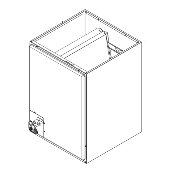
The coils have sweat connect fittings. All coils are shipped with a low
psi nitrogen holding charge. See Figures 1.
SECTION II: SAFETY
This is a safety alert symbol. When you see this symbol on
labels or in manuals, be alert to the potential for personal
injury.
Understand and pay particular attention to the signal words DANGER,
WARNING, or CAUTION.
DANGER indicates an imminently hazardous situation, which, if not
avoided, will result in death or serious injury.
WARNING indicates a potentially hazardous situation, which, if not
avoided, could result in death or serious injury.
CAUTION indicated a potentially hazardous situation, which, if not
avoided may result in minor or moderate injury. It is also used to alert
against unsafe practices and hazards involving only property damage.
Johnson Controls Unitary Products
LIST OF SECTIONS
REFRIGERANT LINE CONNECTION . . . . . . . . . . . . . . . . . . . . . . . . 6
COIL METERING DEVICES . . . . . . . . . . . . . . . . . . . . . . . . . . . . . . . . 7
INSTRUCTING THE OWNER . . . . . . . . . . . . . . . . . . . . . . . . . . . . . 11
AIR SYSTEM ADJUSTMENT . . . . . . . . . . . . . . . . . . . . . . . . . . . . . 11
INSTALLATION VERIFICATION . . . . . . . . . . . . . . . . . . . . . . . . . . . 12
LIST OF FIGURES
Piston Installation . . . . . . . . . . . . . . . . . . . . . . . . . . . . . . . . . . . . . . . . 9
TXV Installation . . . . . . . . . . . . . . . . . . . . . . . . . . . . . . . . . . . . . . . . . 10
TXV Bulb and Equalizer line Installations . . . . . . . . . . . . . . . . . . . . . 10
Proper Bulb Location for TXV . . . . . . . . . . . . . . . . . . . . . . . . . . . . . . 10
Vertical Temperature Bulb Orientation . . . . . . . . . . . . . . . . . . . . . . . 11
CM "N" & "A" Coil . . . . . . . . . . . . . . . . . . . . . . . . . . . . . . . . . . . . . . . 11
Communicating Port of the Furnace . . . . . . . . . . . . . . . . . . . . . . . . . 12
Wiring Diagram - EEV . . . . . . . . . . . . . . . . . . . . . . . . . . . . . . . . . . . . 12
Drain Traps . . . . . . . . . . . . . . . . . . . . . . . . . . . . . . . . . . . . . . . . . . . . 14
Drain Connections with Furnace . . . . . . . . . . . . . . . . . . . . . . . . . . . . 15
Connections with Modular Air Handler . . . . . . . . . . . . . . . . . . . . . . . 15
LIST OF TABLES
Air Flow Data - Static Pressure Drop for CM Models . . . . . . . . . . . . 12
Air Flow Data - Static Pressure Drop for CF Models . . . . . . . . . . . . 12
Improper installation may create a condition where the operation of
the product could cause personal injury or property damage.
Improper installation, adjustment, alteration, service or maintenance
can cause injury or property damage. Refer to this manual for assis-
tance or additional information, consult a qualified installer or service
agency.
The furnace area must not be used as a broom closet or for any other stor-
age purposes, as a fire hazard may be created. Never store items such as
the following on, near or in contact with the furnace.
1. Spray or aerosol cans, rags, brooms, dust mops, vacuum clean-
ers or other cleaning tools.
2. Soap powders, bleaches, waxes or other Cleaning compounds;
plastic items or containers; gasoline, kerosene, cigarette lighter
fluid, dry cleaning fluids or other volatile fluid.
3. Paint thinners and other painting compounds.
4. Paper bags, boxes or other paper products
Never operate the furnace with the blower door removed. To do so could
result in serious personal injury and/or equipment damage.
WARNING
!
WARNING
!
5292154-UIM-A-0317
ISO 9001
Certified Quality
Management System
Advertisement
Table of Contents

Related Manuals for York CF18A


Summary of Contents for York CF18A
-
Page 1: Table Of Contents
INSTALLATION MANUAL FULL-CASED UPFLOW/COUNTERFLOW FOR COOLING/HEAT PUMPS MODELS: CF FULL-CASED MULTI-POSITION FOR COOLING/HEAT PUMPS ISO 9001 MODELS: CM Certified Quality Management System LIST OF SECTIONS GENERAL ..........1 REFRIGERANT LINE CONNECTION . -
Page 2: Pressure Check
Distributor for more information. Check drain pan for cracks or break- age. TABLE 1: Dimensions - CF Upflow/Downflow Full Cased Coils Refrigerant Dimensions 3,4,5 Connections Models Height Width Opening Widths Liquid Vapor CF18A* 19-1/2 14-1/2 13-1/2 13-1/2 CF18B* 17-1/2 16-1/2 16-1/2 FIGURE 1: Pressure Check CF24A*... -
Page 3: Dimensions - Cm Multi-Position Full Cased Coils
5292154-UIM-A-0317 TABLE 2: Dimensions - CM Multi-position Full Cased Coils Dimensions Refrigerant Opening 3,4,5 Connections Models Height Width Widths Liquid Vapor CM18A* 19-1/2 14-1/2 13-1/2 13-1/2 CM18B 17-1/2 16-1/2 16-1/2 CM24A* 19-1/2 14-1/2 13-1/2 13-1/2 CM24B* 17-1/2 16-1/2 16-1/2 CM24C 25-5/8 17-1/2 16-1/2 16-1/2 CM25B... -
Page 4: Coil Installation
5292154-UIM-A-0317 HORIZONTAL POSITION - DRAIN PAN COIL ACCESS PANEL VAPOR LINE HORIZONTAL POSITION - SECONDARY DRAIN FIGURE 4: Duct Flanges - Coils CF / CM VERTICAL OR LIQUID LINE HORIZONTAL POSITION - PRIMARY DRAIN VERTICAL POSITION - SECONDARY DRAIN A0268-001 FIGURE 3: Component Location - Cased Coil CM Model LIMITATIONS These coils should be installed in accordance with all national and local... -
Page 5: Direct Duct Installation (Cf Models)
5292154-UIM-A-0317 Upflow or downflow applications (CF/CM Models): These coils are factory shipped for installation in either upflow or down- flow applications with a minor conversion. 1. Position the coil cabinet on the furnace or modular air handler opening (or the coil cabinet under the furnace or modular air han- dler opening for appropriate air flow) as shown in Figure 5 or 6. -
Page 6: Duct Connections
5292154-UIM-A-0317 FIGURE 12: CM Horizontal Left Application with Modular Air Handler SECTION VI: CONDENSATE DRAIN CONNECTIONS FIGURE 10: Diverter Shroud Installation All drain lines should be pitched 1/4-inch per foot away from unit drain SECTION V: DUCT CONNECTIONS pan and should be no smaller than the coil drain connection. Air supply and return may be handled in one of several ways best Route the drain line so that it doesn’t interfere with accessibility to the suited to the installation. -
Page 7: Cm Horizontal Left Application With Furnace
5292154-UIM-A-0317 6. Insert liquid and suction lines into the coil connections at the coil CAUTION cabinet tubing panel. 7. Wrap a water soaked rag around the coil connection tubes inside the cabinet to avoid transferring excess heat to the coil, TXV, EEV Dry nitrogen should always be supplied through the tubing while it is and temperature sensor if EEV equipped. - Page 8 5292154-UIM-A-0317 CAUTION LIQUID LINE SWIVEL COUPLING (This fitting is a right-handed thread. Turn counter-clockwise to remove.) COIL UNDER PRESSURE. Verify that pressure has been released by depressing Schrader valve PISTON core shown in Figure 1. The coil requires a metering device to be added. TEFLON WASHER See outdoor unit documentation for correct TXV or piston to be used.
-
Page 9: Vapor Line Grommet
5292154-UIM-A-0317 9. After line set is installed, leak test the system. LIQUID LINE / TXV COUPLING Bulb at TXV SENSING BULB (Pass through split hole 10 o’clock TEFLON WASHER TXV BULB in grommet.) position. (Cover completely SCREW with insulation.) CLAMP CLAMP VAPOR TXV / DISTRIBUTOR COUPLING... -
Page 10: Txv Installation
5292154-UIM-A-0317 FIGURE 20: CM “N” & “A” Coil FIGURE 21: Communicating Port of the ECM Modular Blower Control FIGURE 22: Communicating Port of the Furnace Board Johnson Controls Unitary Products... -
Page 11: Instructing The Owner
5292154-UIM-A-0317 INDOOR EQUIPMENT CONTROL COMM PORT USE COPPER CONDUCTORS ONLY. IF ALUMINUM CONDUCTORS ARE PRESENT, ALL APPLICABLE LOCAL AND NATIONAL CODES MUST BE FOLLOWED. EEV MOTOR EEV CONTROL BOARD INDICATORS EEV CONTROL LED DIAGNOSTIC CODES LEGEND LAMP LAMP IPT - INDOOR COIL PRESSURE TRANSDUCER COLOR CONDITION DESCRIPTION... -
Page 12: Installation Verification
TABLE 5: Air Flow Data - Static Pressure Drop for CF Models CFM @ Static Pressure Drop - IWG CFM @ Static Pressure Drop - IWG Coil Coil (Based on dry coil) (Based on dry coil) Size Size CF18A 1030 1152 1261 1363 CM18A 1115 1221 1319... -
Page 13: Location Of Coil Trapped And Plugged Drain Connections With Furnace
5292154-UIM-A-0317 FIGURE 25: Location of Coil Trapped and Plugged Drain Connections with Furnace FIGURE 26: Location of Coil Trapped and Plugged Drain Connections with Modular Air Handler Johnson Controls Unitary Products... -
Page 14: Drain Traps
NOTES Subject to change without notice. Published in U.S.A. 5292154-UIM-A-0317 Copyright © 2017 by Johnson Controls, Inc. All rights reserved. Supersedes: 1187005-UIM-G-0816 York International Corp. 5005 York Drive Norman, OK 73069...