ABB Relion 615 Series Operation Manual
Protection and control
Hide thumbs
Also See for Relion 615 Series:
- Technical manual (1196 pages) ,
- Applications manual (220 pages) ,
- Operation manual (164 pages)
Table of Contents
Advertisement
Quick Links
Advertisement
Table of Contents

Related Manuals for ABB Relion 615 Series


Summary of Contents for ABB Relion 615 Series
- Page 1 ® Relion Protection and Control 615 series Operation Manual...
- Page 3 Document ID: 1MRS756708 Issued: 2010-06-11 Revision: C Product version: 3.0 © Copyright 2010 ABB. All rights reserved...
- Page 4 Copyright This document and parts thereof must not be reproduced or copied without written permission from ABB, and the contents thereof must not be imparted to a third party, nor used for any unauthorized purpose. The software or hardware described in this document is furnished under a license and may be used, copied, or disclosed only in accordance with the terms of such license.
- Page 5 In case any errors are detected, the reader is kindly requested to notify the manufacturer. Other than under explicit contractual commitments, in no event shall ABB be responsible or liable for any loss or damage resulting from the use of this manual or the application of the equipment.
- Page 6 (EMC Directive 2004/108/EC) and concerning electrical equipment for use within specified voltage limits (Low-voltage directive 2006/95/EC). This conformity is the result of tests conducted by ABB in accordance with the product standards EN 50263 and EN 60255-26 for the EMC directive, and with the product standards EN 60255-1 and EN 60255-27 for the low voltage directive.
-
Page 7: Safety Information
Safety information Dangerous voltages can occur on the connectors, even though the auxiliary voltage has been disconnected. Non-observance can result in death, personal injury or substantial property damage. Only a competent electrician is allowed to carry out the electrical installation. National and local electrical safety regulations must always be followed. -
Page 9: Table Of Contents
Table of contents Table of contents Section 1 Introduction...............7 This manual..................7 Intended audience................7 Product documentation...............8 Product documentation set............8 Document revision history.............9 Related documentation..............10 Symbols and conventions..............10 Safety indication symbols............10 Manual conventions..............10 Functions, codes and symbols............11 Section 2 Environmental aspects...........15 Sustainable development..............15 Disposing of the IED.................15 Section 3 615 series overview............17 Overview...................17... - Page 10 Table of contents Identifying the device..............34 Adjusting the display contrast............35 Changing the local HMI language..........35 Changing display symbols............36 Navigating in the menu..............36 Menu structure...............37 Scrolling the LCD view............37 Changing the default view............38 Viewing single-line diagram............38 Changing single-line diagram symbol formats.......39 Browsing setting values...............39 Editing values................40 Editing numerical values............40...
- Page 11 Table of contents Disturbance reports..............70 Internal IED errors...............70 IED parametrization................71 IED settings for IED functionality..........71 IED settings for different operating conditions......71 Section 6 Operating procedures.............73 Monitoring..................73 Indications...................73 Monitoring indication messages..........73 Monitoring an internal IED fault ..........74 Monitoring condition monitoring data........74 Measured and calculated values..........74 Measured values..............74 Using the local HMI for monitoring.........75...
- Page 12 Table of contents Indication messages.................88 Internal faults................88 Warnings..................90 LED and display messages............92 Correction procedures..............92 Rebooting the software..............92 Restoring factory settings............92 Setting the password..............93 Identifying IED application problems...........93 Inspecting the wiring...............93 Sample data interruptions............94 Section 8 Commissioning...............95 Commissioning checklist..............95 Checking the installation..............95 Checking the power supply............95 Checking CT circuits..............96 Checking VT circuits..............96...
- Page 13 IED parametrization..............115 Defining disturbance recorder channel settings....116 Configuring analog inputs.............116 Testing IED operation..............116 Selecting the test mode.............116 Testing the digital I/O interface..........117 Testing functions...............117 Selecting the internal fault test..........118 ABB Product Data Registration............118 Section 9 Glossary...............121 615 series Operation Manual...
-
Page 15: Section 1 Introduction
Section 1 1MRS756708 C Introduction Section 1 Introduction This manual The operation manual contains instructions on how to operate the IED once it has been commissioned. The manual provides instructions for monitoring, controlling and setting the IED. The manual also describes how to identify disturbances and how to view calculated and measured power grid data to determine the cause of a fault. -
Page 16: Product Documentation
Section 1 1MRS756708 C Introduction Product documentation 1.3.1 Product documentation set Engineering manual Engineering manual Engineering manual Installation manual Installation manual Installation manual Commissioning manual Commissioning manual Commissioning manual Operation manual Operation manual Operation manual Service manual Service manual Service manual Application manual Application manual Application manual... -
Page 17: Document Revision History
Document revision history Document revision/date Product series version History A/2009-03-04 First release B/2009-07-03 Content updated C/2010-06-11 Content updated to correspond to the product series version Download the latest documents from the ABB web site http:// www.abb.com/substationautomation. 615 series Operation Manual... -
Page 18: Related Documentation
Section 1 1MRS756708 C Introduction 1.3.3 Related documentation Product series- and product-specific manuals can be downloaded from the ABB web site http://www.abb.com/substationautomation. Symbols and conventions 1.4.1 Safety indication symbols The electrical warning icon indicates the presence of a hazard which could result in electrical shock. -
Page 19: Functions, Codes And Symbols
Section 1 1MRS756708 C Introduction To navigate between the options, use • HMI menu paths are presented in bold, for example: Select Main menu/Settings. • Menu names are shown in bold in WHMI, for example: Click Information in the WHMI menu structure. •... - Page 20 Section 1 1MRS756708 C Introduction Function IEC 61850 IEC 60617 IEC-ANSI Admittance based earth-fault EFPADM1 Yo> -> (1) 21YN (1) protection EFPADM2 Yo> -> (2) 21YN (2) EFPADM3 Yo> -> (3) 21YN (3) Transient / intermittent earth-fault INTRPTEF1 Io> -> IEF 67NIEF protection Non-directional (cross-country) earth...
- Page 21 Section 1 1MRS756708 C Introduction Function IEC 61850 IEC 60617 IEC-ANSI Thermal overload protection for MPTTR1 3Ith>M motors Binary signal transfer BSTGGIO1 Stabilized and instantaneous differential protection for 2W TR2PTDF1 3dI>T transformers Line differential protection and related measurements, stabilized LNPLDF1 3dI>L and instantaneous stages Numerical stabilized low impedance...
- Page 22 Section 1 1MRS756708 C Introduction Function IEC 61850 IEC 60617 IEC-ANSI Circuit-breaker condition monitoring SSCBR1 CBCM CBCM Trip circuit supervision TCSSCBR1 TCS (1) TCM (1) TCSSCBR2 TCS (2) TCM (2) Current circuit supervision CCRDIF1 MCS 3I MCS 3I Fuse failure supervision SEQRFUF1 FUSEF Protection communication...
-
Page 23: Section 2 Environmental Aspects
Section 2 1MRS756708 C Environmental aspects Section 2 Environmental aspects Sustainable development Sustainability has been taken into account from the beginning of the product design including the pro-environmental manufacturing process, long life time, operation reliability and disposing of the IED. The choice of materials and the suppliers have been made according to the EU RoHS directive (2002/95/EC). - Page 24 Section 2 1MRS756708 C Environmental aspects electronic waste. These handlers can sort the material by using dedicated sorting processes and dispose of the product according to the local requirements. Table 3: Materials of the IED parts Parts Material Case Metallic plates, parts and screws Steel Plastic parts , LCP...
-
Page 25: Section 3 615 Series Overview
Section 3 1MRS756708 C 615 series overview Section 3 615 series overview Overview 615 series is a product family of IEDs designed for protection, control, measurement and supervision of utility substations and industrial switchgear and equipment. The design of the IEDs has been guided by the IEC 61850 standard for communication and interoperability of substation automation devices. -
Page 26: Local Hmi
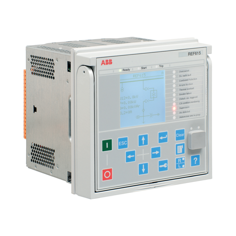
Section 3 1MRS756708 C 615 series overview Local HMI REF615 Overcurrent Dir. earth-fault Voltage protection Phase unbalance Thermal overload Breaker failure Disturb. rec. Triggered CB condition monitoring Supervision Arc detected Autoreclose shot in progr. A070704 V3 EN Figure 2: Example of 615 series LHMI The LHMI of the IED contains the following elements: •... - Page 27 Section 3 1MRS756708 C 615 series overview Table 4: Characters and rows on the view Character size Rows in view Characters on row Small, mono-spaced (6x12 5 rows pixels) 10 rows with large screen Large, variable width (13x14 4 rows min 8 pixels) 8 rows with large screen...
-
Page 28: Leds
Section 3 1MRS756708 C 615 series overview The display is updated either cyclically or based on changes in the source data such as parameters or events. 3.2.2 LEDs The LHMI includes three protection indicators above the display: Ready, Start and Trip. - Page 29 Section 3 1MRS756708 C 615 series overview A070680 V2 EN Figure 4: LHMI keypad with object control, navigation and command push- buttons and RJ-45 communication port Close Escape Enter Clear Uplink LED Communication LED Open Left 10 Down 11 Right 12 Key 13 Remote/Local 14 Menu...
- Page 30 Section 3 1MRS756708 C 615 series overview Navigation The arrow buttons are used for navigation. To scroll information, press the arrow button several times or simply keep it pressed down. Table 6: Navigation push-buttons Name Description • Leaving setting mode without saving the values. •...
-
Page 31: Local Hmi Functionality
Section 3 1MRS756708 C 615 series overview 3.2.4 Local HMI functionality 3.2.4.1 Protection and alarm indication Protection indicators The protection indicator LEDs are Ready, Start and Trip. Table 8: Ready LED LED state Description Auxiliary supply voltage is disconnected. Normal operation. Flashing Internal fault has occurred or the IED is in test mode. -
Page 32: Parameter Management
Section 3 1MRS756708 C 615 series overview Table 11: Alarm indications LED state Description Normal operation. All activation signals are off. • Non-latched mode: activation signal is still on. • Latched mode: activation signal is still on, or it is off but has not been acknowledged. -
Page 33: Web Hmi
Section 3 1MRS756708 C 615 series overview A070816 V2 EN Figure 5: RJ-45 communication port and indication LEDs 1 Uplink LED 2 Communication LED When a computer is connected to the IED, the IED's DHCP server for the front interface assigns an IP address to the computer. The fixed IP address for the front port is 192.168.0.254. -
Page 34: Command Buttons
Section 3 1MRS756708 C 615 series overview A070754 V3 EN Figure 6: Example view of the WHMI The WHMI can be accessed locally and remotely. • Locally by connecting your laptop to the IED via the front communication port. • Remotely over LAN/WAN. -
Page 35: Authorization
Section 3 1MRS756708 C 615 series overview Name Description Rejecting changes. Showing context sensitive help messages. Clearing events. Triggering the disturbance recorder manually. Saving values to CSV file format. Freezing the values so that updates are not displayed. Receiving continuous updates to the monitoring view. -
Page 36: Communication
Section 3 1MRS756708 C 615 series overview Table 13: Predefined user categories Username User rights VIEWER Read only access OPERATOR • Selecting remote or local state with (only locally) • Changing setting groups • Controlling • Clearing indications ENGINEER • Changing settings •... -
Page 37: Pcm600 Tool
Section 3 1MRS756708 C 615 series overview All communication connectors, except for the front port connector, are placed on integrated optional communication modules. The IED can be connected to Ethernet- based communication systems via the RJ-45 connector (100Base-TX) or the fibre- optic LC connector (100Base-FX). -
Page 38: Connectivity Packages
REF615 Connectivity Package Ver. 3.0 or later • REM615 Connectivity Package Ver. 3.0 or later • RET615 Connectivity Package Ver. 3.0 or later • REU615 Connectivity Package Ver. 3.0 or later Download connectivity packages from the ABB web site http:// www.abb.com/substationautomation 615 series Operation Manual... -
Page 39: Section 4 Using The Hmi
Section 4 1MRS756708 C Using the HMI Section 4 Using the HMI Using the local HMI You must be logged in and authorized to use the LHMI. Password authorization is disabled by default and can be enabled via the LHMI or WHMI. To enable password authorization, select Main menu/ Configuration/Authorization/Local override. -
Page 40: Logging Out
Section 4 1MRS756708 C Using the HMI A070890 V2 EN Figure 9: Entering password Press to confirm the login. • To cancel the procedure, press A070889 V2 EN Figure 10: Error message indicating wrong password The current user level is shown on the LCD's upper right corner in the icon area. -
Page 41: Turning The Display Backlight On
Section 4 1MRS756708 C Using the HMI A070837 V3 EN Figure 11: Logging out • To cancel logout, press 4.1.3 Turning the display backlight on The display backlight is normally off. It turns on during the display test at power up. •... -
Page 42: Identifying The Device
Section 4 1MRS756708 C Using the HMI The control position cannot be simultaneously local and remote but it can be disabled when neither of the positions is active. To control the IED, log in with the appropriate user rights. 4.1.5 Identifying the device The IED information includes detailed information about the device, such as revision and serial number. -
Page 43: Adjusting The Display Contrast
Section 4 1MRS756708 C Using the HMI A071160 V2 EN Figure 13: IED information 4.1.6 Adjusting the display contrast Adjust the display contrast anywhere in the menu structure to obtain optimal readability. • To increase the contrast, press simultaneously • To decrease the contrast, press simultaneously The selected contrast value is stored in the non-volatile memory if you are logged in and authorized to control the IED. -
Page 44: Changing Display Symbols
Section 4 1MRS756708 C Using the HMI A071010 V2 EN Figure 14: Changing the LHMI language To change the language using a shortcut, press simultaneously anywhere in the menu. 4.1.8 Changing display symbols Use the keypad to switch between the display symbols IEC 61850, IEC 60617 and IEC-ANSI. -
Page 45: Menu Structure
Section 4 1MRS756708 C Using the HMI 4.1.9.1 Menu structure The Main menu contains main groups which are divided further into more detailed submenus. • Events • Measurements • Disturbance records • Settings • Configuration • Monitoring • Tests • Information •... -
Page 46: Changing The Default View
Section 4 1MRS756708 C Using the HMI 4.1.9.3 Changing the default view The default view of the display is Measurements unless set otherwise. Select Main menu/Configuration/HMI/Default view and press Change the default view with Press to confirm the selection. 4.1.10 Viewing single-line diagram The single-line diagram is created with PCM600. -
Page 47: Changing Single-Line Diagram Symbol Formats
Section 4 1MRS756708 C Using the HMI 4.1.10.1 Changing single-line diagram symbol formats Select Main menu/Configuration/HMI/SLD symbol format and press Change symbol format with Press to confirm the selection. GUID-02F6C094-9B0E-4624-AAD2-780355A3F64B V1 EN Figure 18: Selecting IEC as single-line diagram symbol format 4.1.11 Browsing setting values Select Main menu/Settings/Settings and press... -
Page 48: Editing Values
Section 4 1MRS756708 C Using the HMI A070859 V3 EN Figure 20: Example of submenus in the Settings menu 4.1.12 Editing values • To edit values, log in with the appropriate user rights. 4.1.12.1 Editing numerical values Select Main menu/Settings and then a setting. The last digit of the value is active. -
Page 49: Editing String Values
Section 4 1MRS756708 C Using the HMI decimal values, the change can be fractions 0.1, 0.01, 0.001 (...) depending on the active digit. For parameters with defined steps, digits smaller than the step value cannot be edited. Press to move the cursor to another digit. To select the minimum or maximum value, select the arrow symbol in front of the value. -
Page 50: Editing Enumerated Values
Section 4 1MRS756708 C Using the HMI When editing string values, the cursor moves to the first character. Press to change the value of an active character. One press changes the value by one step. Press to move the cursor to another character. •... -
Page 51: Clearing And Acknowledging
Section 4 1MRS756708 C Using the HMI • If the parameter has an edit-copy, the original parameter value is restored. • If the parameter does not have an edit-copy, the edited parameter value remains visible until you reboot the IED. However, the edited value is not stored in non-volatile memory and the reboot restores the original value. -
Page 52: Using The Local Hmi Help
Section 4 1MRS756708 C Using the HMI 4.1.15 Using the local HMI help Press to open the help view. Scroll the text with if the help text exceeds the display area. To close the help, press Using the Web HMI WHMI is disabled by default. -
Page 53: Identifying The Device
Section 4 1MRS756708 C Using the HMI A070924 V4 EN Figure 27: WHMI logout 4.2.3 Identifying the device The IED information includes detailed information about the device, such as revision and serial number. Click Information in the WHMI menu structure. Click a submenu to see the data. -
Page 54: Navigating In The Menu
Section 4 1MRS756708 C Using the HMI A070925 V4 EN Figure 28: Device information 4.2.4 Navigating in the menu The menu tree structure on the WHMI is almost identical to the one on the LHMI. Use the menu bar to access different views. •... -
Page 55: Menu Structure
Section 4 1MRS756708 C Using the HMI A070945 V4 EN Figure 29: Navigating in the WHMI menus 4.2.4.1 Menu structure The Main menu contains main groups which are divided further into more detailed submenus. • Events • Measurements • Disturbance records •... - Page 56 Section 4 1MRS756708 C Using the HMI • Select Control/SLD in the main menu or click Single Line Diagram in the menu bar to view the single-line diagram. GUID-961E57A5-BFDF-4BB5-9615-B8DD4C3707BE V1 EN Figure 30: Viewing the single-line diagram with IEC symbols 615 series Operation Manual...
-
Page 57: Showing All Parameters
Section 4 1MRS756708 C Using the HMI GUID-C78B4218-3979-41ED-8B4E-83EACC433182 V1 EN Figure 31: Viewing the single-line diagram with ANSI symbols 4.2.6 Showing all parameters Click Parameter list in the main menu. 615 series Operation Manual... -
Page 58: Editing Values
Section 4 1MRS756708 C Using the HMI A070963 V4 EN Figure 32: Show all parameters Click Print to print out all parameters on paper. Click Save to save all parameters in CSV file format. 4.2.7 Editing values Click the menu in the WHMI tree. Click the submenu to see function blocks. - Page 59 Section 4 1MRS756708 C Using the HMI A070929 V4 EN Figure 33: Enable writing to edit a value The selected setting group is shown in the Setting Group drop-down list. The active setting group is indicated with an asterisk *. Edit the value.
-
Page 60: Committing Settings
Section 4 1MRS756708 C Using the HMI A070934 V3 EN Figure 35: Warning indicating that the entered value is incorrect • If writing values fails, a warning dialog box is displayed. GUID-E10EE091-CFB9-4278-9FA4-7340C26F5814 V2 EN Figure 36: Warning indicating that the values were not written to the IED If writing is enabled accidentally, click Disable Write. - Page 61 Section 4 1MRS756708 C Using the HMI Some parameters have an edit-copy. If editing is cancelled, the values with an edit- copy are immediately restored to the original value. The values without an edit- copy, such as string values, are restored to the original value only after a reboot even though the edited value is not stored in the flash memory.
-
Page 62: Clearing And Acknowledging
Section 4 1MRS756708 C Using the HMI A070932 V4 EN Figure 38: Committing changes Committing values will take a few seconds. If the values are not committed, they are not taken into use and they are lost after a reboot. 4.2.9 Clearing and acknowledging Reset, acknowledge or clear all messages and indications, including LEDs and... - Page 63 Section 4 1MRS756708 C Using the HMI A070935 V5 EN Figure 39: Selecting clear menu In the New Value box, click Clear to select the item to be cleared. Click Write to IED. 615 series Operation Manual...
-
Page 64: Selecting The Programmable Leds View
Section 4 1MRS756708 C Using the HMI A070936 V5 EN Figure 40: Clearing indications and LEDs 4.2.10 Selecting the programmable LEDs view The programmable LEDs view shows the status of the programmable LEDs. These are the same LEDs that are located on the upper right side of the LHMI panel. •... -
Page 65: Selecting The Event View
Section 4 1MRS756708 C Using the HMI A070946 V4 EN Figure 41: Monitoring programmable LEDs 4.2.11 Selecting the event view The event view contains a list of events produced by the application configuration. When event page is opened it displays up to 100 latest events at one time. The event list is updated automatically. - Page 66 Section 4 1MRS756708 C Using the HMI A070947 V4 EN Figure 42: Monitoring events Click Freeze to stop updating the event list. Select a page from the drop-down menu to view older documents. 615 series Operation Manual...
-
Page 67: Selecting The Disturbance Record View
Section 4 1MRS756708 C Using the HMI GUID-328EBE0A-26D4-4063-AA1F-051C302EBCE2 V1 EN Figure 43: Events view Click Save to save the events in CSV file format. The CSV file can be opened with a spreadsheet program such as OpenOffice.org Calc or Microsoft Excel. Click Clear events to clear all events from the IED. -
Page 68: Uploading Disturbance Records
Section 4 1MRS756708 C Using the HMI GUID-2B46A09D-730E-45D3-BE30-20546BB6F8AD V2 EN Figure 44: Disturbance record view 4.2.12.1 Uploading disturbance records Click Disturbance records on the menu bar. To upload a disturbance record, click the icons in the CFG and DAT columns of the record. -
Page 69: Triggering The Disturbance Recorder Manually
Section 4 1MRS756708 C Using the HMI GUID-0280828D-0DFF-4C83-90A0-D8E57E17E51A V1 EN Figure 45: Uploading a disturbance record Save both the files in the same folder on your computer. Open the disturbance record files with a suitable program. 4.2.12.2 Triggering the disturbance recorder manually Click Disturbance records on the menu bar. -
Page 70: Deleting Disturbance Records
Section 4 1MRS756708 C Using the HMI GUID-4F5661CB-2317-4F4C-9DA2-BFADFA71BA3E V2 EN Figure 46: Manual triggering 4.2.12.3 Deleting disturbance records Click Disturbance records on the menu bar. Delete records. • Click Delete all to delete all records. • Select one or more recordings and click Delete to delete selected records. 615 series Operation Manual... -
Page 71: Selecting Phasor Diagrams
Section 4 1MRS756708 C Using the HMI GUID-E109C24F-8CC9-4074-A175-DA4820BA7913 V2 EN Figure 47: Deleting disturbance records Click OK to confirm or Cancel to cancel the deletion. 4.2.13 Selecting phasor diagrams Click Phasor diagrams in the menu bar. 615 series Operation Manual... - Page 72 Section 4 1MRS756708 C Using the HMI A070948 V4 EN Figure 48: Monitoring phasors Toggle the diagram visibility by selecting it from the drop-down menu. GUID-5F3C9CC8-1AE8-4235-836F-AC93E1E73708 V3 EN Figure 49: Toggling the diagram visibility 615 series Operation Manual...
- Page 73 Section 4 1MRS756708 C Using the HMI Visible diagrams are indicated with an asterisk *. Change the size of the diagram by changing the zoom value. GUID-690A11A9-FEC4-4558-A68F-16FBAC500E3B V3 EN Figure 50: Zooming the diagram Click Freeze to stop updating the phasor diagram. No updates are displayed in the diagram.
-
Page 74: Selecting Fault Records
Section 4 1MRS756708 C Using the HMI A071226 V4 EN Figure 51: The arrow extends outside the circle if the current value is too high Install an SVG plugin to view the phasor diagrams. 4.2.14 Selecting fault records • Select from the main menu Monitoring/Recorded data/Fault record to view a list of all available fault records. - Page 75 Section 4 1MRS756708 C Using the HMI GUID-A6D3E116-CBAC-4F6B-8853-D97D32F73A71 V1 EN Figure 52: Fault records GUID-A49A6D73-2E18-48B3-9ECA-17908590688D V1 EN Figure 53: Fault record parameters 615 series Operation Manual...
-
Page 76: Using The Web Hmi Help
Section 4 1MRS756708 C Using the HMI 4.2.15 Using the Web HMI help The context sensitive WHMI help provides information, for example, of a single parameter. • Move the mouse over the to display the help dialog box. A070927 V4 EN Figure 54: Opening the WHMI help 615 series... -
Page 77: Section 5 Ied Operation
Section 5 1MRS756708 C IED operation Section 5 IED operation Normal operation In a normal IED use situation, the basic operation includes monitoring and checking procedures. • Monitoring measured values • Checking object states • Checking function setting parameters • Checking events and alarms All basic operations can be performed via the LHMI, WHMI or with PCM600. -
Page 78: Disturbance Recording Triggering
Section 5 1MRS756708 C IED operation Document the disturbance before clearing the information from the IED. Only authorized and skilled personnel should analyze possible errors and decide on further actions. Otherwise, stored disturbance data can be lost. 5.2.1 Disturbance recording triggering Disturbance recordings are normally triggered by IED applications when they detect fault events. -
Page 79: Ied Parametrization
Section 5 1MRS756708 C IED operation Only authorized and skilled personnel should analyze the errors and decide on further actions. The IED records system registrations, IED status data and events. Document all the recorded data from the IED before resetting the tripping and IED lockout functions. -
Page 81: Section 6 Operating Procedures
Section 6 1MRS756708 C Operating procedures Section 6 Operating procedures Monitoring 6.1.1 Indications The operation of the IED can be monitored via three different indications on the LHMI. • Three indicator LEDs with fixed functionality: Ready, Start and Trip • 11 programmable LEDs •... -
Page 82: Monitoring An Internal Ied Fault
Section 6 1MRS756708 C Operating procedures 6.1.1.2 Monitoring an internal IED fault The flashing green LED indicates an internal IED fault. Internal IED fault messages are shown in a dialog box. A071144 V2 EN Figure 56: Fault indication Select Main menu/Monitoring/IED status/Self-supervision to monitor the latest fault indication. -
Page 83: Using The Local Hmi For Monitoring
Section 6 1MRS756708 C Operating procedures Table 15: Measured values Indicator Description IL1-A Current measured on phase L1 IL2-A Current measured on phase L2 IL3-A Current measured on phase L3 Measured earth-fault current Measured residual voltage U12-kV Measured phase-to-phase voltage U12 U23-kV Measured phase-to-phase voltage U23 U31-kV... -
Page 84: Creating Disturbance Recordings
Section 6 1MRS756708 C Operating procedures 6.1.3.1 Creating disturbance recordings Normally disturbance recordings are triggered by the IED applications but the recording can also be triggered manually. Select Main menu/Disturbance records. Select Trig recording with Press , change the value with and press again. -
Page 85: Controlling And Uploading Disturbance Recorder Data
Section 6 1MRS756708 C Operating procedures A070863 V3 EN Figure 58: Monitoring disturbance recorder via the LHMI 6.1.3.3 Controlling and uploading disturbance recorder data Disturbance recorder data can be controlled and read with PCM600. It can also be uploaded via WHMI. For more information, see PCM600 documentation. -
Page 86: Monitoring Events
Section 6 1MRS756708 C Operating procedures 6.1.3.5 Monitoring events Event view contains a list of events produced by the application configuration. Each event takes one view area. The header area shows the currently viewed event index and the total amount of the events. The most recent event is always first. Select Main Menu/Events. -
Page 87: Controlling
Section 6 1MRS756708 C Operating procedures Controlling 6.2.1 Controlling circuit breaker or contactor The primary equipment can be controlled via the LHMI with the Open and Close buttons when the IED is set to local control mode and you are authorized to access control operations. -
Page 88: Controlling With Single-Line Diagram
Section 6 1MRS756708 C Operating procedures The time between selecting the object and giving a control command is restricted by an adjustable time-out. When an object is selected, the control command has to be given within this time. 6.2.2 Controlling with single-line diagram In the single-line diagram view it is possible to open and close the controllable object. -
Page 89: Resetting Ied
Section 6 1MRS756708 C Operating procedures Resetting IED 6.3.1 Clearing and acknowledging via the local HMI All messages and indications, including LEDs and latched outputs as well as registers and recordings can be reset, acknowledged or cleared with the Clear button. -
Page 90: Changing The Ied Functionality
Section 6 1MRS756708 C Operating procedures Changing the IED functionality 6.4.1 Defining the setting group 6.4.1.1 Activating a setting group IED settings are planned in advance for different operation conditions by calculating setting values to different setting groups. The active setting group can be changed by the IED application or manually from the menu. -
Page 91: Copying A Setting Group
Section 6 1MRS756708 C Operating procedures Remember to document the changes you make. 6.4.1.2 Copying a setting group Setting group 1 can be copied to another group or to all available groups. Select Main menu/Settings/Setting group/Copy group 1 and press Change the options with and press to confirm the selection. - Page 92 Section 6 1MRS756708 C Operating procedures A071166 V3 EN Figure 69: Selecting a setting group To browse the settings, scroll the list with and to select a setting press To browse different function blocks, scroll the list with and to select a function block press .
-
Page 93: Activating Programmable Leds
Section 6 1MRS756708 C Operating procedures A071168 V3 EN Figure 71: Selecting the setting group value Only values within the selected setting group can be changed. Press to change the value and to confirm the selection. A070922 V3 EN Figure 72: Editing the setting group value The active setting group is indicated with an asterisk * . - Page 94 Section 6 1MRS756708 C Operating procedures Select Main menu/Configuration/ HMI/Autoscroll delay and press Select delay time with Press to confirm the selection. GUID-799BFDDC-93D0-4887-818E-E7C7905F236D V1 EN Figure 73: Autoscroll delay 615 series Operation Manual...
-
Page 95: Section 7 Troubleshooting
Inspect the IED visually. • Inspect the IED visually to find any physical error causes. • If you can find some obvious physical damage, contact ABB for repair or replacement actions. Check whether the error is external or internal. •... -
Page 96: Checking The Time Synchronization
The IED continues to perform internal tests during the fault situation. The internal fault code indicates the type of internal IED fault. When a fault appears, record the code so that it can be reported to ABB customer service. 615 series Operation Manual... - Page 97 Section 7 1MRS756708 C Troubleshooting A071144 V2 EN Figure 74: Fault indication Table 17: Internal fault indications and codes Fault indication Fault code Additional information Internal Fault An internal system error has occurred. System error Internal Fault A file system error has occurred. File system error Internal Fault Internal fault test activated manually by...
-
Page 98: Warnings
LHMI. The warning indication message can be manually cleared. If a warning appears, record the name and code so that it can be provided to ABB customer service. - Page 99 Section 7 1MRS756708 C Troubleshooting A071222 V2 EN Figure 75: Warning Table 18: Warning indications and codes Warning indication Warning code Additional information Warning A watchdog reset has occurred. Watchdog reset Warning The auxiliary supply voltage has dropped Power down det. too low.
-
Page 100: Led And Display Messages
Section 7 1MRS756708 C Troubleshooting Warning indication Warning code Additional information Warning Error in protection communication. Protection comm. Warning A continuous light has been detected on ARC1 cont. light the ARC light input 1. Warning A continuous light has been detected on ARC2 cont. -
Page 101: Setting The Password
Section 7 1MRS756708 C Troubleshooting overwritten with the default values. During normal use, a sudden change of the settings can cause a protection function to trip. 7.3.3 Setting the password If user authorization is off or the user is logged in as an administrator, user passwords can be set via the LHMI or WHMI or with PCM600. -
Page 102: Sample Data Interruptions
In case of permanent faults, the measurement chain should be checked to remove the origin of the faulty measurement data. In case of persistent faults originating from IED's internal faults, contact ABB for repair or replacement actions. 615 series Operation Manual... -
Page 103: Section 8 Commissioning
Section 8 1MRS756708 C Commissioning Section 8 Commissioning Commissioning checklist Familiarize yourself with the IED and its functionality before you start the commissioning work. • Ensure that you have all the needed station drawings such as single line and wiring diagrams. •... -
Page 104: Checking Ct Circuits
Section 8 1MRS756708 C Commissioning 8.2.2 Checking CT circuits The CTs must be connected in accordance with the terminal diagram provided with the IED, both with regards to phases and polarity. The following tests are recommended for every primary CT or CT core connected to the IED. •... -
Page 105: Checking Binary Input And Output Circuits
Section 8 1MRS756708 C Commissioning Test the circuitry. • Polarity check • VT circuit voltage measurement (primary injection test) • Earthing check • Phase relationship • Insulation resistance check The polarity check verifies the integrity of circuits and the phase relationships. The polarity should be measured as close to the IED as possible to ensure that most of the wiring is also checked. -
Page 106: Using Pcm600
Section 8 1MRS756708 C Commissioning • Numbers 0-1 • Letters a-z, A-Z • Space • Special characters !"#%&'()*+´-./:;<=>?@[\]^_`{|}~ User authorization is disabled by default and can be enabled via the LHMI or WHMI Main Menu/Configuration/Authorization. Table 19: Predefined user categories Username LHMI WHMI password User rights... -
Page 107: Communication Options
Section 8 1MRS756708 C Commissioning Set up or get the IP addresses of the IEDs. Set up the PC for a direct link or connect the PC or workstation to the network. Configure the IED IP addresses in the PCM600 project for each IED. The addresses are used for communication by the OPC interface of PCM600. - Page 108 Section 8 1MRS756708 C Commissioning To open Network Connections, click Start, point to Settings, click Control Panel, and then double-click Network Connections. Double-click the connection that you want to configure, and then click Properties. Select the TCP/IP protocol from the list of configured components using this connection and click Properties.
- Page 109 Section 8 1MRS756708 C Commissioning A071224 V1 EN Figure 77: Obtaining IP address automatically Close all open windows by clicking OK and start PCM600. Administrator rights are requested to change the configuration as described above. Setting the rear communication To set up a standard PC with MicroSoft Windows operating system for rear communication: To open Network Connections, click Start, point to Settings, click Control Panel, and then double-click Network Connections.
- Page 110 Section 8 1MRS756708 C Commissioning A071162 V1 EN Figure 78: Selecting TCP/IP protocol Choose Use the following IP address. Enter an IP address and a subnet mask. Make sure that the IP address is unique, that is not used by any other IED on the network.
- Page 111 Section 8 1MRS756708 C Commissioning A071164 V1 EN Figure 79: Setting IP address and subnet mask Close all open windows by clicking OK and start PCM600. Administrator rights are requested to change the configuration as described above. Setting IED's IP address in PCM600 In PCM600 the IED's IP address can be defined via the first window of the wizard by including a new IED in the project or by entering the IED's IP address in the Object Properties window.
-
Page 112: Setting Ied And Communication
Section 8 1MRS756708 C Commissioning Setting IED and communication 8.5.1 Communication settings The IED is provided with an RJ-45 connector on the LHMI. The connector is mainly used for configuration and setting purposes. The fixed IP address for the front port is 192.168.0.254. Different communication ports are available via optional communication modules. - Page 113 Section 8 1MRS756708 C Commissioning Table 20: COM port parameters in different HW options COM parameter Values Hardware options Fiber mode 0 = No fiber Used in the fiber-optic mode only. Note that No fiber mode is the same 1 = Fiber light ON/loop as the galvanic mode.
-
Page 114: Serial Link Diagnostics And Monitoring
Section 8 1MRS756708 C Commissioning 8.5.1.2 Serial link diagnostics and monitoring Serial communication diagnostics and monitoring is divided between the serial link driver and the serial communication protocol. The lower level physical and protocol- independent aspects of the UART-based serial communication are monitored in the serial link driver. - Page 115 Section 8 1MRS756708 C Commissioning Table 22: Basic diagnostic counters Counter Function Characters received Counts all incoming non-erroneous characters. This counter operates regardless of if the serial driver is set to detect a whole protocol link frame or just separate characters. Frames received Counts all protocol specific non-erroneous frames received.
-
Page 116: Defining Ethernet Port Settings
Section 8 1MRS756708 C Commissioning Table 24: Link status Parameter Function Link status Link status in write direction: By writing 1 to the parameter the diagnostic counters are reset to 0. Link status in monitoring direction: If the driver is in use by any communication protocol, the monitoring value shows 1. -
Page 117: Communication Checklist
Section 8 1MRS756708 C Commissioning 8.5.1.7 Communication checklist Check the physical connections. After the settings are changed, allow them to be stored in NVRAM (!S on LHMI). Reboot the unit to allow the setting changes to take effect in DNP3. If the WHMI connection is missing, enable the IED's WHMI setting and prevent the Web browser from attempting to use a proxy Internet Options/ Connections/LAN Settings/Advanced/Exceptions (for example... -
Page 118: Adjusting The Display Contrast
Section 8 1MRS756708 C Commissioning A071010 V2 EN Figure 80: Changing the LHMI language To change the language using a shortcut, press simultaneously anywhere in the menu. 8.5.2.2 Adjusting the display contrast Adjust the display contrast anywhere in the menu structure to obtain optimal readability. -
Page 119: Changing The Default View
Section 8 1MRS756708 C Commissioning 8.5.2.4 Changing the default view The default view of the display is Measurements unless set otherwise. Select Main menu/Configuration/HMI/Default view and press Change the default view with Press to confirm the selection. 8.5.2.5 Setting the system time and time synchronization Select Main menu/Configuration/Time/System time. -
Page 120: Setting Ied Parameters
Section 8 1MRS756708 C Commissioning DST on time: 01:00 DST on date: 25.03 DST on day: DST off time: 01:00 DST off date: 25.10 DST off day: Set the DST on day and DST off day to "not in use" to determine the exact date and time for the DST shift. - Page 121 Section 8 1MRS756708 C Commissioning Browsing and editing setting group values Select Main menu/Settings/Settings and press Select the setting group to be viewed with and press to confirm the selection. A071166 V3 EN Figure 82: Selecting a setting group To browse the settings, scroll the list with and to select a setting press To browse different function blocks, scroll the list with...
- Page 122 Section 8 1MRS756708 C Commissioning A071168 V3 EN Figure 84: Selecting the setting group value Only values within the selected setting group can be changed. Press to change the value and to confirm the selection. A070922 V3 EN Figure 85: Editing the setting group value The active setting group is indicated with an asterisk * .
-
Page 123: Ied Parametrization
Section 8 1MRS756708 C Commissioning A071150 V3 EN Figure 86: Active setting group Select the setting group with Press to confirm the selection or to cancel. A071152 V3 EN Figure 87: Selecting the active setting group Commit the settings. Remember to document the changes you make. 8.5.3.2 IED parametrization IED parameters are set via the LHMI, WHMI or PCM600. -
Page 124: Defining Disturbance Recorder Channel Settings
Section 8 1MRS756708 C Commissioning Document all changes to parameter settings. For more information, see PCM600 documentation. 8.5.3.3 Defining disturbance recorder channel settings Select Main Menu/Configuration/Disturbance recorder/Channel settings. Press to scroll the view. To change channel settings, press Each analog channel has an equal set of parameters and correspondingly, each binary channel has an equal set of parameters. -
Page 125: Testing The Digital I/O Interface
Section 8 1MRS756708 C Commissioning The test mode is useful for simulated testing of functions and outputs without providing current inputs. Select Main menu/Tests/IED test/Test mode and press A071154 V2 EN Figure 88: Entering test mode Select the test mode status with Press to confirm the selection. -
Page 126: Selecting The Internal Fault Test
A071156 V2 EN Figure 89: Internal fault test Select the value with Press to confirm the selection. ABB Product Data Registration The ABB Product Data Registration feature traces composition changes related to the IED's SW or HW. 615 series Operation Manual... - Page 127 Section 8 1MRS756708 C Commissioning After a composition change, an LCT indication is seen on the LHMI at the IED start- up. At this point, PCM600 should be connected to the IED as it reads the changed data from the IED. The LCT indication is cleared in the same way as other indications.
-
Page 129: Section 9 Glossary
Section 9 1MRS756708 C Glossary Section 9 Glossary Application Configuration tool in PCM600; Trip status ANSI American National Standards Institute Address Resolution Protocol CAT 5 A twisted pair cable type designed for high signal integrity COMTRADE Common format for transient data exchange for power systems. - Page 130 Section 9 1MRS756708 C Glossary IEC 61850-8-1 A communication protocol based on the IEC 61850 standard series Intelligent electronic device Internet protocol IP address A set of four numbers between 0 and 255, separated by periods. Each server connected to the Internet is assigned a unique IP address that specifies the location for the TCP/IP protocol.
- Page 131 Section 9 1MRS756708 C Glossary Resistance temperature detector Substation configuration language Single-line diagram Simplified notation for representing a three-phase power system. Instead of representing each of three phases with a separate line or terminal, only one conductor is represented. Single-line diagram Signal Matrix tool in PCM600 Connector type for glass fibre cable Shielded twisted-pair...
- Page 136 Contact us ABB Oy Distribution Automation P.O. Box 699 FI-65101 VAASA, Finland Phone +358 10 22 11 +358 10 22 41094 www.abb.com/substationautomation...