Samsung VP-D371 Service Manual
Hide thumbs
Also See for VP-D371:
- Service manual (29 pages) ,
- Owner's instruction book (114 pages) ,
- Owner's instruction manual (110 pages)
Table of Contents
Advertisement
ELECTRONICS
◆ If you want to know additional information which is not included on this
Service Manual, Please refer to the SKP(Samsung Knowledge Portal)
web site.
Area
North America
URL ; http://service.samsungportal.com
Latin America
URL ; http://latin.samsungportal.com
CIS
URL ; http://cis.samsungportal.com
Europe
URL ; http://europe.samsungportal.com
China
URL ; http://china.samsungportal.com
Asia
URL ; http://asia.samsungportal.com
Mideast & Africa
URL ; http://mea.samsungportal.com
This Service Manual is a property of Samsung Electronics Co .,Ltd.
Any unauthorized use of Manual can be punished under applicable
International and/or domestic law.
Web Site
© Samsung Electronics Co., Ltd. FEB. 2007
Printed in Korea
AD82-00183A
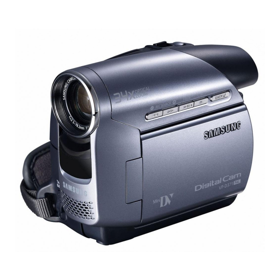
DIGITAL VIDEO CAMCORDER
Chassis : Dragon III
BASIC : VP-D371
Application Models
: VP-D371(i), VP-D371W(i),
VP-D372WH(i), VP-D375W(i),
VP-D975W(i)
Application Area
:
XEF, XEU, XEG, XET, XEV, XEC, XSA, CDM,
XST, XEO, XEH, XEP, XEE, EAP, EUR, XEN,
HACO, TAW, TIT, COL, SEO, XSS, SED, XSH,
XSG, FES, XTL, CHN, ZAM, STS, SMR, XFA,
ITN, KNT, XSE, FPT, RAD, AFR, AND, UMG
MEA, SEA
SERVICE
DIGITAL VIDEO CAMCORDER
Manual
Merit & Character regarding Product
ΠShooting & compact Design
´ Direct Print System : PictBridge
TM
ˇ LED Light
¨ High quality MPEG4
ˆ Still image Interpolation
Ø Real Wide mode (16:9)/WIDE LCD
∏ 34X ZOOM (Normal model)
26X ZOOM (Mega model)
" USB 2.0 Streaming
Advertisement
Table of Contents

Related Manuals for Samsung VP-D371


Summary of Contents for Samsung VP-D371
- Page 1 Mideast & Africa URL ; http://mea.samsungportal.com ” USB 2.0 Streaming This Service Manual is a property of Samsung Electronics Co .,Ltd. © Samsung Electronics Co., Ltd. FEB. 2007 Any unauthorized use of Manual can be punished under applicable Printed in Korea International and/or domestic law.
-
Page 2: Table Of Contents
CONTENTS 1. Precautions 1-1 ~ 1-4 1-1 Safety Precaution (1-1) 1-2 Servicing Precautions (1-3) 1-3 ESD Precautions (1-4) 2. Product Specification 2-1 ~ 2-4 2-1 Product Specification (2-1) 2-2 Chassis Product Specification (2-2) 2-3 Accessories Supplied with Camcorder (2-3) 3. Alignment and Adjustments 3-1 ~ 3-16 3-1 VCR Adjustment (3-1) - Page 3 8. Wiring Diagram 8-1 ~ 8-2 9. PCB Diagrams 9-1 ~ 9-10 9-1 Main PCB (9-2) 9-2 Rear PCB (9-5) 9-3 LCD PCB (VP-D371(i)) (9-5) 9-4 LCD PCB (VP-D371W(i)/D372WH(i)/D375W(i)/D975W(i)) (9-6) 9-5 Function PCB (9-6) 9-6 Jack PCB (9-7) 9-7 Front PCB (VP-D372WH(i)/D375W(i)/D975W(i))
- Page 4 CONTENTS 10-13 Zoom motor Drive (Main PCB) (10-14) 10-14 2.5” LCD (LCD PCB (VP-D371(i))) (10-15) 10-15 2.7” LCD (LCD PCB (VP-D371W(i)/D372WH(i)/D375W(i)/D975W(i))) (10-16) 10-16 CCD Normal (CCD PCB (VP-D371(i)/D371W(i)/D372WH(i)/D375W(i)))(10-17) 10-17 CCD Mega (CCD PCB (VP-D975W(i))) (10-18) 10-18 Jack (Jack PCB) (10-19)
- Page 5 Metal Part an electrical return path to the chassis. Any current measured must not exceed 0.5mA. Reverse the instrument power cord plug in the out- ohmmeter let and repeat the test. See Fig. 1-1. Fig. 1-2 Insulation Resistance Test Samsung Electronics...
- Page 6 (5) antenna wiring. Always inspect in all areas tinuously and new instructions are issued whenev- for pinched, out-of-place, or frayed wiring, Do not er appropriate. change spacing between a component and the printed-circuit board. Check the AC power cord for damage. Samsung Electronics...
-
Page 7: Precautions 1-1
Components identi- fied by shading, by( ) or by ( ) in the circuit dia- gram are important for safety or for the characteris- tics of the unit. Always replace them with the exact replacement components. Samsung Electronics... -
Page 8: Esd Precautions
(6) Do not remove a replacement ESD device from its protective package until immediately before your are ready to install it.(Most replacement ESD devices are packaged with leads electrically short- ed together by conductive foam, aluminum foil or comparable conductive materials). Samsung Electronics... -
Page 9: Product Specification 2-1
Power source DC 8.4V lithium lon Battery Pack 7.4V Power Source type Lithium lon Battery Pack, Power supply (110V~240V) 50/60Hz External dimension Height 3.82 inches, Length 4.69 Inches, width 2.16 inches General Weiht 0.75lb Internal MIC Omni-directional stereo microphone Samsung Electronics... -
Page 10: Chassis Product Specification
Carrying Case / Tape Opt. / Opt. Opt. / Opt Opt. / Opt Opt. / Opt Opt. / Opt. S-Cable / Scart Jack X / X X / X X / X X / X X / X Samsung Electronics... - Page 11 VP-D371W/XEF Model Standard Audio/Video Cable AD39-00001A of VP-D371W/XEF Model Standard Instruction Book AD68-01227H of VP-D371W/XEF Model Standard Lithium Battery AD43-00030A of VP-D371W/XEF Model Standard AD67-00427A Lens Cover of VP-D371W/XEF Model Standard Lens Cover Strap AD72-00049A of VP-D371W/XEF Samsung Electronics...
- Page 12 Product Specification MEMO Samsung Electronics...
-
Page 13: Alignment And Adjustments
EASY-Q (Mode Up) Changes mode. DISPLAY (Mode Down) 3) How to get into the VCR adjust mode [STEP 1] Œ Connect the Power source. ´ Set the Power Switch to “PLAY” position and Mode Switch to “TAPE” position. Fig. 3-1 Samsung Electronics... - Page 14 <Table 3-2> Mode(Address) Name Value Description SWP Position Head Switching Position Adjust Œ Get into VCR ADJUST mode. ´ Move to the VCR ADJUST address “858”. ˇ Play standard tape, and “Head Switching Position” will be adjusted automatically. Samsung Electronics...
-
Page 15: Camera Adjustment
Buttons Description OK Button push (Confirm) Stores changed value in the adjustment and auto adjustment mode. T( ) (Data Down) Changes data in the adjustment state. W( ) (Data Up) EASY-Q (Mode Up) Changes mode. DISPLAY (Mode Down) Samsung Electronics... - Page 16 ¨ Monitor OSD shows Fig. 3-6. Then Camera adjustment mode has been activated successfully. [STEP 3] If you want to finish the adjustment mode, you have to do Power Reset.The Power Reset means that you pull out the power source and pull in it again. Fig. 3-4 Fig. 3-5 Samsung Electronics...
- Page 17 ˆ Press the "EASY-Q"(Mode Up)/"DISPLAY"(Mode Down) buttons so that OSD shows "00D0 XX XX". Ø Press the "OK"Button (Confirm). Never impact on the lens when adjusting zoom and focus Lens. The OSD shows "OK" after finishing the adjustment. (Show Fig. 3-8) Fig. 3-7 Samsung Electronics...
- Page 18 1500~2000 Lux. ˆ Press the "OK" Button (Confirm) to ensure that white spot on a vectorscope is moving in the middle of screen. Ø The OSD shows "OK" after finishing the adjustment. (Show Fig. 3-8) Samsung Electronics...
- Page 19 Alignment and Adjustments Lens Zoom Track Auto White Balance (indoor) Auto White Balance (outdoor) Fig. 3-8 Samsung Electronics...
-
Page 20: Deck Adjustment
1) Set the power-supply output to approx. 3V~5V. <Table 3-4> 2) Choose the polarity (depending on whether load- Movement of Chassis ing or unloading). Unloading 3) Supply the voltage to the Motor Loading, and set to the desired mode. Loading Fig. 3-10 Samsung Electronics... - Page 21 ΠIn EJECT mode, clean the tape path system(from Pole Tension P1 through Pole Review P8, Pinch Roller and Capstan Shaft) and the Lower Drum. Using the lens tissue soaked in ethyl alcohol. Note : Make sure that no oil or grease adheres to the lens tissue. Fig. 3-11 Samsung Electronics...
- Page 22 (Oil contaminated with dust might cause the bearings to wear out or seize.) ◆ A “drop”of oil is defined as the amount attached to the tip of a Ø 2mm stick as shown in Fig. 3-11. Fig. 3-12 Samsung Electronics 3-10...
- Page 23 Note : Check if the Arm Tension can be moved toward arrow “C” in PB mode. 3) Reassembly Œ For the removal of the Housing Ass’y refer to 4-2-2 (page 4-6). ARM TENSION Œ CAP ADJUST ´ Fig. 3-13 3-11 Samsung Electronics...
- Page 24 Reel S, T table should each be 3.9±0.1mm. 3) Mounting Œ For the removal of the Idler Ass’y refer to 4-2-3 (page 4-7). ´ For the removal of the Housing Ass’y refer to 4-2-2 (page 4-6). Fig. 3-15 Samsung Electronics 3-12...
- Page 25 ¨ Check that the waveform of the RF signal is flat at both inlet and outlet(A in Fig. 3-15). If not flat (B or C in Fig. 3-15), do adjustments 3-3-5(b) through 3-3-5(d). CNR02 9 10 RF Signal (Pin 3 of CNR02) Head Switching (Pin 2 of CNR02) Fig. 3-16 Rear PCB (Top Side) 3-13 Samsung Electronics...
- Page 26 Capstan. (If the tape is twisted, turn P8, Fig. 3-18) ´ Set to REV mode and observe the outlet waveform of PB RF signal. (Fig. 3-19) ˇ If the outlet waveform is out-of-spec, turn P8 counterclockwise, and redo steps 1 and 2. (DEFECTIVE) (CORRECT) Fig. 3-20 Samsung Electronics 3-14...
- Page 27 If the track pitch is not uniform, do section 3-3-5(b) (Tracking adjustment) and 3-3-5(c) (P8 adjustment). ´ Set to CUE mode. Confirm that the waveform peaks still have a uniform pitch. (Fig. 3-22 B) If the track pitch is not uniform, do section 3-3-5(b) (Tracking Adjustment). a b c Fig. 3-23 3-15 Samsung Electronics...
- Page 28 4) Tape Path Check ΠIn CUE and REV modes, check that the tape is not curled around the P3, P6 upper flange and P8 upper/Lower flanges. MOTOR CAPSTAN Fig. 3-24 P1 P2 P3 P4 P6 P7 Fig. 3-25 Samsung Electronics 3-16...
-
Page 29: Disassembly And Reassembly
2) Remove FFC-Front ¨. Œ 1 SCREW (M1.7 X 5 B) ¨ FFC-FRONT ´ 1 SCREW (M1.7 X 5 B) ˇ 2 SCREWS (T1.7 X 4 B) CAUTION : FFC-Front Must be remove with care Fig. 4-1 Ass’y Front Removal Samsung Electronics... - Page 30 ˇ COVER-LI BATTERY ˆ 1 SCREW (M1.7 X 3 B) ∏ ASS’Y LEFT Ø 1 SCREW (M1.7 X 5 B) CAUTION : FPC Must be remove with care Be careful while pulling Mic-Harness. Fig. 4-2 Ass’y Left Removal Samsung Electronics...
- Page 31 4) Disconnect Board to board connector ¨, Which is connecting PCB-Rear and Main-PCB. 5) Remove Ass’y-rear ˆ by indicated direction. ˇ COVER-DC JACK ˆ ASS’Y REAR Œ 1 SCREW (M1.7 X 5 B) ¨ BOARD TO BOARD ´ 2 SCREWS CONNECOTOR (M1.7 X 3 B) Fig. 4-3 Ass’y Rear Removal Samsung Electronics...
- Page 32 2) Disconnect Board to Board Connector ´, Which is connecting PCB-CCD and Main PCB. 3) Remove Ass’y-lens ˇ by Indicated direction. ˇ ASS’Y LENS ´ DISCONNECT BOARD TO BOARD CONNECTOR Œ 2 SCREWS (M1.7 X 3 B) Fig. 4-4 Ass’y Lens Removal Samsung Electronics...
- Page 33 3) Remove Main PCB ¨ from Ass’y right by indicated dircection. ´ 5FPC Œ 1FPC ¨ MAIN PCB ˇ 1 SCREW (M1.7 X 3 B) CAUTION : FPC, FFC Must be remove with care Fig. 4-5 Main PCB Removal Samsung Electronics...
- Page 34 2) Open Cover Housing ´ indicated direction while pushing Knob-tape eject ˇ downward. 3) Pull Ass’y-main deck ¨ downward. ´ COVER HOUSING ˇ KNOB-TAPE EJECT ˇ 3 SCREWS (M1.4 X 5 B) ¨ ASS’Y MAIN DECK Fig. 4-6 Ass’y Main Deck Removal Samsung Electronics...
-
Page 35: Deck
1) Set the power-supply output to approximately 3V~5V, and connect it to the Motor Loading. 2) Choose the polarity depending on whether loading or unloading. (See Table 4-1) 3) Supply the voltage to the Motor Loading. <Table 4-1> Movement of Chassis Loading Unloading Fig. 4-7 Loading and Unloading Samsung Electronics... - Page 36 2) Separate the Hook L and Hook R and then lift it. and then locked. 3) Separate the Shape of Pin L and R ˆ from Cam Parts Ø, ∏ of Sub Chassis and then lift the Housing Ass’y ”. Fig. 4-8 Housing Ass’y Samsung Electronics...
- Page 37 2) Mount the Cover Reel Ass’y ´ to the Sub Chassis in Ass’y ´. the reverse direction of arrow. 2) Then lift the Idler Ass’y ˇ. 3) Secure the 2 Screws Œ. Fig. 4-9 Cover Reel Ass’y, Idler Ass’y Samsung Electronics...
- Page 38 Spring Tension Œ is same. Note 2 : When moving inspecting, must be inspect Back Tension. Note 3 : When reassembling, confirm that pin of Arm Tension insert into the Guide Cam. Fig. 4-10 Arm Tension Ass’y, Reel Disk S Samsung Electronics 4-10...
- Page 39 3) Lift up Sub Chassis Ass’y ´ from Main Chassis ˇ. applying 3V~5V to the Motor Loading. Note 2 : When reassembling, confirm that pin of Arm Review insert into the Guide Cam. Fig. 4-11 Sub Chassis Samsung Electronics 4-11...
- Page 40 1) After turned Arm Review Œ in the direction of the direction of arrow “A”. arrow “A”, and then lift up. 2) Lift up the Reel Disk T ´. 3) Lift up the Brake T ˇ. Fig. 4-12 Arm Review, Reel Disk T, Brake T Samsung Electronics 4-12...
- Page 41 1) Remove 1 Screw Œ and then remove the Spring Plate Drum ´. 2) Lift up the Drum ˇ. 3) Remove 1 Screw ¨ and then lift up the Holder FPC ˆ. Fig. 4-13 Drum, Holder FPC Samsung Electronics 4-13...
- Page 42 Note 2 : Disassemble and reassemble in unload mode. Roller S ˇ and T ¨. Note 3 : After assembling, make sure that loading and unloading work correctly by applying 3V~5V to the Motor Loading. Fig 4-13 Guide Rail Ass’y Samsung Electronics 4-14...
- Page 43 ASSEMBLE POINT (TWO ARROWS) 2 SCREWS ˆ Ø GEAR TENSION GEAR CAM MAIN ∏ ¨ MOTOR LOADING ASS'Y 1 SCREW ´ ˇ 1 HOOK Œ PT WELDING 2 POINTS Fig. 4-14 Motor Loading, Gear Tension, Gear Cam Main Samsung Electronics 4-15...
- Page 44 Lever Pinch ¨ from the Hook of Main Chassis ˆ. 3) Lift up the Arm Pinch Roller Ø. 5) Lift up the Slide Main ∏. 6) Lift up the Lever Eject ”. Fig. 4-15 Motor Capstan, Arm Pinch Roller, Slide Main, LeverEject Samsung Electronics 4-16...
- Page 45 Timming ˇ on the Gear Pully ¨. 2) Hang the Timing Belt ˇ to the upper gear of the Gear Capstan ´ and mount the Gear Capstan ´. 3) Assemble the Washer Slit Œ. Fig. 4-16 Gear Pully, Timing Belt, Gear Capstan Samsung Electronics 4-17...
- Page 46 Disassembly and Reassembly MEMO Samsung Electronics 4-18...
-
Page 47: Exploded View And Parts List
5-11 Mechanical Parts (Main Chassis) - - - - - - - - - - - - - - - - - - - - - - - - - - - - - - 5-16 5-12 Mechanical Parts (Sub Chassis) - - - - - - - - - - - - - - - - - - - - - - - - - - - - - - - 5-18 Samsung Electronics... -
Page 48: Ass'y Chassis
Exploded View and Parts List 5-1 Ass’y Chassis C352 M001 C314 P180 W122 C594 P002 (M1.4 X 5 B) W126 (M1.7 X 4 B) C201 W126 P001 (M1.7 X 4 B) C960 Samsung Electronics... - Page 49 BRACKET-LENS;DRAGON3-PJ,STS,T0.5,W54.2,L C314 AD97-10701B ASSY-CCD;DRAGON3-PJ,PAL,ASSY-CCD C352 AD97-12012A ASSY-FRONT;ASSY,DRAGON3-PJ,SC-D371 C594 AD61-02357A PLATE-CCD;DRAGON2-PJ,AL,T1,W21,L25,-,- C960 AD63-01105A SHIELD-CASE MAIN;DRAGON3-PJ,SPTE,T0.25,W M001 AD97-12038A ASSY-DECK;DD-4B,-,- P001 AD92-00088M ASSY PCB-MAIN BOARD;VP-D371W/XEF,DRAGON3 P002 AD97-11996A ASSY-CCD BOARD;DRAGON3-PJ,PAL,CCD BOARD P180 AD97-12061A ASSY-ZOOM LENS;ASSY,DRAGON3-PJ,33X ZOOM W122 6009-001325 SCREW-SPECIAL;CH,+,,M1.4,L5(1.9),ZPC(BLK W126 6003-001300 SCREW-TAPTITE;CH,+,B,M1.7,L4,ZPC(BLK),SW Samsung Electronics...
-
Page 50: Ass'y Left
Exploded View and Parts List 5-2 Ass’y Left P247 L051 W112 W112 P091 L001 Samsung Electronics... - Page 51 Exploded View and Parts List Loc. No Parts No. Description ; Specification Q’ty S.N.A Remark L001 AD97-12019J ASSY-LCD;ASSY,DRAGON3-PJ,VP-D372W L051 AD97-12006A ASSY-CVF;ASSY,DRAGON3-PJ,SC-D371 P091 AD97-12018B ASSY-CASE LEFT;ASSY,DRAGON3-PJ,NON MEMOR P247 AD97-12255A ASSY-COVER TOP;ASSY,DRAGON3-PJ,CARD(X),O W112 6003-001453 SCREW-TAPTITE;BH,+,B,M1.7,L4,ZPC(BLK) Samsung Electronics...
-
Page 52: Ass'y Right
Exploded View and Parts List 5-3 Ass’y Right W206 C049 C047 W206 W206 C012 C014 W206 P055 C010 C957 W112 Samsung Electronics... - Page 53 Q’ty S.N.A Remark C010 AD97-12024A ASSY-CASE RIGHT;ASSY,DRAGON3-PJ,SC-D371 C012 AD97-12017A ASSY-LINK HOUSING;ASSY,DRAGON3-PJ,SC-D37 C014 AD97-10795A ASSY-BELT GRIP;ASSY,DRAGON2-PJ,SCD6550 C047 AD63-00889A COVER-HOUSING;DD-4A,ABS94HB,-,-,-,-,-,BL C049 AD64-01618A KNOB-TAPE EJECT;DRAGON3-PJ,ABS 94HB,T1.0 C957 AD61-02527A PLATE-GROUND RIGHT;DRAGON2-PJ,SUS304,T0. P055 AD97-12136A ASSY-JACK;ASSY,DRAGON3-PJ,COMPO AV, USB W112 6003-001453 SCREW-TAPTITE;BH,+,B,M1.7,L4,ZPC(BLK) W206 6001-001373 SCREW-MACHINE;PH,T0.5,+,-,M1.7,L3.0,ZPC( Samsung Electronics...
-
Page 54: Ass'y Lcd
Exploded View and Parts List 5-4 Ass’y LCD L017 C958 C846 L015 C958 L016 C423 C953 L013 W118 L014 C962 C956 L0533 C349 W206 P004 L011 L074 Samsung Electronics... - Page 55 CASE-LCD BOTTOM 2.7;DRAGON3-PJ,ABS 94HB L014 AD63-01071A COVER-HINGE TOP;DRAGON3-PJ,ABS 94HB,T1.0 L015 AD63-01072A COVER-HINGE BOTTOM;DRAGON3-PJ,ABS 94HB,T L016 AD97-10863A ASSY-HINGE;ASSY,RAINBOW1(33X),- L017 AD97-12092A ASSY-LCD FPC;DRAGON3-PJ,SC-D375,- L0533 AD07-00063A LCD-PANEL;A027CW01,DRAGON3-PJ,112320,63. L074 AD97-12020J ASSY-LCD TOP;ASSY,DRAGON3-PJ,VP-D372W P004 AD92-00094A ASSY PCB-LCD BOARD;SC-D375/XAA,2.7LCD,D W118 6003-001291 SCREW-TAPTITE;CH,+,B,M1.4,L3.0,ZPC(BLK), W206 6001-001373 SCREW-MACHINE;PH,T0.5,+,-,M1.7,L3.0,ZPC( Samsung Electronics...
-
Page 56: Ass'y Case Left
C961 C843 S.N.A : Service Not Available Loc. No Parts No. Description ; Specification Q’ty S.N.A Remark C849 AD61-02736A BRACKET-GROUND LEFT;DRAGON3-PJ,STS,T0.5, C951 AD39-00138A HARNESS-RING;DRAGON3,#24,-,1,97mm,BLK,24 C954 AD69-00875A PAD-LEFT;DRAGON3-PJ,RUB-OTH,T1.0,W12, C959 AD63-01102A SHEET-TAPE SPEAKER;DRAGON3 P054 AD97-12135A ASSY-SPEAKER;DRAGON3-PJ,SC-D375,- W113 6002-001085 SCREW-TAPPING;CH,+,2,M1.7,L5,ZPC(BLK),SW 5-10 Samsung Electronics... -
Page 57: Ass'y Case Right
PLATE-POWER;TIGER-PJ,SUS301 1/2H,T0.5,W1 C020 AD64-01624A LOCKER-POWER;DRAGON3-PJ,PC,GREEN,-,-,- C022 AD73-00006A RUBBER--GUIDE DECK;BUTHYL RUB,-,VP-D50,- C059 AD61-02731A HOLDER-POWER;DRAGON3-PJ,POM,T1.5,W14.9,L C308 AD61-02047A PLATE-SPRING POWER;TIGER-PJ,SUS301 1/2H, C334 AD63-01078A COVER-DC JACK;DRAGON3-PJ,URETHAN,T1.5,W8 C399 AD61-02364A PLATE-NUT;DRAGON2-PJ,SECC,T0.8,W3,L3,-,- C497 AD64-01615A BUTTON-MENU;DRAGON3-PJ,ABS 94HB,D28.9,-, C698 AD61-01494A SPRING ETC-LOCKER POWER;RAPIDO-PJ,STS SW W126 6003-001300 SCREW-TAPTITE;CH,+,B,M1.7,L4,ZPC(BLK),SW Samsung Electronics 5-11... -
Page 58: Ass'y Cvf
AD61-12033A BRACKET-NUT;SV-D10,SECC,-,-,-,-,T0.8 C378 AD61-02728A HOLDER-CVF LENS;DRAGON3-PJ,ABS 94HB,T1.0 C386 AD67-00025A LENS--EVF-M-G1;-,-,PMMA,3.5,D13,-,EVF C546 AD63-01077A COVER-EYE CUP;DRAGON3-PJ,ABS 94HB,T1.5,W C589 AD61-02186A HOLDER-CVF SLIDE;RAPIDO2,POM,T1.0,W6.1,L C686 AD64-01619A KNOB-CVF;DRAGON3-PJ,PC,T1.0,W10.2,L5.0, C978 AD61-02733A HOLDER-CVF MAIN;DRAGON3-PJ,ABS L054 AD97-12134A ASSY-UNIT CVF;DRAGON3-PJ,SC-D375,- P311 AD97-12022A ASSY-CASE CVF;ASSY,DRAGON3-PJ,SC W113 6002-001085 SCREW-TAPPING;CH,+,2,M1.7,L5,ZPC(BLK),SW 5-12 Samsung Electronics... -
Page 59: Ass'y Jack
W112 W112 C029 P022 C207 Loc. No Parts No. Description ; Specification Q’ty S.N.A Remark C028 AD64-01617A KNOB-ZOOM;DRAGON3-PJ,ABS 94HB,T1.0,W11,L C029 AD61-02732A HOLDER-ZOOM;DRAGON3-PJ,POM,T1.5,W23.8,L1 C207 AD61-02737A BRACKET-JACK;DRAGON3-PJ,STS,T0.5,W70.5,L C305 AD61-02814A SPRING ETC-ZOOM;DRAGON3-PJ,SUS304WPB,0.4 P022 AD92-00091B ASSY PCB-JACK BOARD;SC-D371/XAA,DRAGON3- W112 6003-001453 SCREW-TAPTITE;BH,+,B,M1.7,L4,ZPC(BLK) Samsung Electronics 5-13... -
Page 60: Ass'y Rear
S.N.A Remark C041 AD61-02723A CASE-REAR;DRAGON3-PJ,ABS 94HB,T1.5,W34.3 C044 AD64-01180B KNOB-BATTERY EJECT;OMEGA2-PJ(2M),ABS 94H C045 AD61-02734A HOLDER-BATTERY EJECT;DRAGON3-PJ,POM,T1.5 C306 AD61-01625B SPRING ETC-BATTERY EJECT;THETA2-PJ,SUS30 C850 AD63-00703A COVER-BATTERY B;DRAGON-PJ,ABS 94HB,T3.8, P009 AD92-00090A ASSY PCB-REAR BOARD;SC-D375/XAA,DRAGON3- P101 AD97-12007A ASSY-CASE REAR;ASSY,DRAON3-PJ W112 6003-001453 SCREW-TAPTITE;BH,+,B,M1.7,L4,ZPC(BLK) 5-14 Samsung Electronics... -
Page 61: Ass'y Front
C031 Loc. No Parts No. Description ; Specification Q’ty S.N.A Remark C031 AD63-00934A SHEET-MIC;OASIS-PJ,######,T0.5,W7,L21,BL C032 AD73-00205A RUBBER-MIC;DRAGON3-PJ,TPS,D22.8,#### 15' C034 AD61-02719A CASE-FRONT;DRAGON3-PJ,ABS 94HB,T2.0,W34. C208 AD61-12033A BRACKET-NUT;SV-D10,SECC,-,-,-,-,T0.8 C339 AD97-12025B ASSY-MIC;ASSY,DRAOGN3-PJ C352 AD97-12012A ASSY-FRONT;ASSY,DRAGON3-PJ C553 AD61-02744A HOLDER-MIC;DRAGON3-PJ,PC,T1.2,W24.9,L24. W112 6003-001453 SCREW-TAPTITE;BH,+,B,M1.7,L4,ZPC(BLK) Samsung Electronics 5-15... -
Page 62: Mechanical Parts (Main Chassis)
Exploded View and Parts List 5-11 Mechanical Parts (Main Chassis) M019 M016 M018 W107 M020 M021 W101 W104 W106 M022 W103 M011 M013 W106 M017 M012 W105 M202 M023 M203 M024 M416 M026 M010 M014 M015 5-16 Samsung Electronics... - Page 63 AD66-00292A PULLEY-BELT-TIMING;DD-4,POLYURETHAN,-,-, M024 AD66-00069A GEAR-CAPSTAN;DD-3,DYAMID,0.4,28,-,-,PCD M026 AD66-00219A GEAR-PULLEY;DD-4,DURACON M90-44,0.3,44,- M202 6031-001417 WASHER-PLAIN;POLYSLIDE,-,ID0.8,D3.0,T0.2 M203 6031-001430 WASHER-PLAIN;POLYSLIDER,-,ID0.8,D2.5,T0. M416 AD97-10558A ASSY-ARM PINCH;ASSY,DD-4A,ASSY W101 6001-001575 SCREW-MACHINE;PH,+,M1.4,L3.5,ZPC(WHT),SW W103 6001-001591 SCREW-MACHINE;PH,+,M1.4,L4(1.5),ZPC(BLK) W104 6001-001715 SCREW-MACHINE;BH,+,M1.4,L2.2,ZPC(BLK) W105 6001-001590 SCREW-MACHINE;PH,+,M1.4,L2.2,ZPC(BLK),SW W106 6009-001319 SCREW-SPECIAL;BH,+,-,M1.4,L2.6,ZPC(YEL), W107 6001-001452 SCREW-MACHINE;BH,+,-,M1.4,L2.5,ZPC(BLK), Samsung Electronics 5-17...
-
Page 64: Mechanical Parts (Sub Chassis)
Exploded View and Parts List 5-12 Mechanical Parts (Sub Chassis) M041 C353 M042 W101 S302 M036 M043 M044 M203 S310 M032 M035 M037 M038 M033 M034 M030 5-18 Samsung Electronics... - Page 65 M038 AD97-06402A ASSY-ARM-REVIEW;-,DD-4,ASSY M041 AD61-01194A HOUSING-LOCK L;DD-4,DURACON M90-44DURACO M042 AD61-01195A HOUSING-LOCK R;DD-4,DURACON M90-44 DURA M043 AD61-01159A HOLDER-BAND;DD-4,DURACON M90-44,-,-,-,NA M044 AD69-00425A BAND-TENSION;DD-4,LUMIRROR,-,-,-,WHITE,- M203 6031-001430 WASHER-PLAIN;POLYSLIDER,-,ID0.8,D2.5,T0. S302 AD97-10559A ASSY-COVER REEL BRAKE;ASSY,DD-4A,ASSY S310 AD66-00374A BRAKE-S SOFT;DD-4A,ZYTEL 70G-43L,-,-,NAT W101 6001-001575 SCREW-MACHINE;PH,+,M1.4,L3.5,ZPC(WHT),SW Samsung Electronics 5-19...
- Page 66 Exploded View and Parts List MEMO 5-20 Samsung Electronics...
-
Page 67: Electrical Parts List
2203-006048 C-CER,CHIP;100nF,10%,10V,X7R,1 1 SA C202 2203-006048 C-CER,CHIP;100nF,10%,10V,X7R,1 1 SA C203 2203-000585 C-CER,CHIP;0.22nF,10%,50V,X7R, 1 SA C322 2203-006048 C-CER,CHIP;100nF,10%,10V,X7R,1 1 SA C204 2203-006361 C-CER,CHIP;10000nF,10%,10V,X5R 1 SA C323 2203-006048 C-CER,CHIP;100nF,10%,10V,X7R,1 1 SA Samsung Electronics This Document can not be used without Samsung’s authorization... - Page 68 2203-006474 C-CER,CHIP;22000nF,20%,6.3V,X5 1 SA C510 2203-006361 C-CER,CHIP;10000nF,10%,10V,X5R 1 SA C705 2203-000254 C-CER,CHIP;10nF,10%,16V,X7R,10 1 SA C511 2203-005922 C-CER,CHIP;4700NF,20%,6.3V,X5R 1 SA C706 2203-000254 C-CER,CHIP;10nF,10%,16V,X7R,10 1 SA C512 2203-005061 C-CER,CHIP;100nF,+80-20%,16V,Y 1 SA Samsung Electronics This Document can not be used without Samsung’s authorization...
- Page 69 2203-000254 C-CER,CHIP;10nF,10%,16V,X7R,10 1 SA CZ18 2203-006048 C-CER,CHIP;100nF,10%,10V,X7R,1 1 SA CD21 2203-006048 C-CER,CHIP;100nF,10%,10V,X7R,1 1 SA CZ19 2203-005923 C-CER,CHIP;1000NF,20%,6.3V,X5R 1 SA CD22 2203-006048 C-CER,CHIP;100nF,10%,10V,X7R,1 1 SA D351 0404-001096 DIODE-SCHOTTKY;1SS393,40V,100m 1 SA Samsung Electronics This Document can not be used without Samsung’s authorization...
- Page 70 TR-SMALL SIGNAL;2SA1774-Q,PNP, 1 SA R211 2007-000164 R-CHIP;150KOHM,5%,1/16W,TP,100 1 SA Q502 0501-000225 TR-SMALL SIGNAL;2SC4617,NPN,20 1 SA Q503 0504-000168 TR-DIGITAL;RN1104,NPN,100mW,47 1 SA R212 2007-008015 R-CHIP;75ohm,1%,1/16W,TP,1005 1 SA R213 2007-000142 R-CHIP;2.7KOHM,5%,1/16W,TP,100 1 SA Samsung Electronics This Document can not be used without Samsung’s authorization...
- Page 71 2007-000162 R-CHIP;100Kohm,5%,1/16W,TP,100 1 SA R417 2007-000157 R-CHIP;47Kohm,5%,1/16W,TP,1005 1 SA R5302 2007-000171 R-CHIP;0ohm,5%,1/16W,TP,1005 1 SA R418 2007-000155 R-CHIP;27Kohm,5%,1/16W,TP,1005 1 SA R5304 2007-000171 R-CHIP;0ohm,5%,1/16W,TP,1005 1 SA R429 2007-000483 R-CHIP;1OHM,5%,1/8W,TP,2012 1 SA Samsung Electronics This Document can not be used without Samsung’s authorization...
- Page 72 2007-001325 R-CHIP;3.3Kohm,5%,1/16W,TP,100 1 SA RD01 2007-000139 R-CHIP;220ohm,5%,1/16W,TP,1005 1 SA R614 2007-000140 R-CHIP;1Kohm,5%,1/16W,TP,1005 1 SA RD02 2007-000172 R-CHIP;10ohm,5%,1/16W,TP,1005 1 SA R615 2007-000157 R-CHIP;47Kohm,5%,1/16W,TP,1005 1 SA RD03 2007-000172 R-CHIP;10ohm,5%,1/16W,TP,1005 1 SA Samsung Electronics This Document can not be used without Samsung’s authorization...
- Page 73 2007-000171 R-CHIP;0ohm,5%,1/16W,TP,1005 1 SA QR06 0504-000168 TR-DIGITAL;RN1104,NPN,100mW,47 1 SA RX03 2007-000171 R-CHIP;0ohm,5%,1/16W,TP,1005 1 SA RZ01 2007-000143 R-CHIP;4.7Kohm,5%,1/16W,TP,100 1 SA QR07 0504-000168 TR-DIGITAL;RN1104,NPN,100mW,47 1 SA RR01 2007-000162 R-CHIP;100Kohm,5%,1/16W,TP,100 1 SA Samsung Electronics This Document can not be used without Samsung’s authorization...
- Page 74 M012 AD66-00208A GEAR-TENSION;DD-4,PBT3300,0.5, 1 SA SWL03 3404-001216 SWITCH-TACT;12V DC,20mA,160gf, 1 SA M013 AD66-00375A GEAR-CAM MAIN;DD-4A,TS-25A,-,5 1 SA SWL04 3404-001216 SWITCH-TACT;12V DC,20mA,160gf, 1 SA M014 AD66-00212A SLIDER-MAIN;DD-4,SUS430 CP,T0. 1 SA Samsung Electronics This Document can not be used without Samsung’s authorization...
- Page 75 CAP-PINCH ROLLER;DURACON,DD-3, 1 SNA 0601-001294 LED-IR;SIDE-VIEW,2mm,75mW,6V,9 1 SA AD66-00225A REEL-REFLECTOR;DD-4,POLYESTER, 1 SNA AD61-01198A SPRING ETC-BRAKE S SOFT;DD-4,S 1 SNA AD81-00003A WASHER-REEL;DD-4,-,-,-,-,-,- 1 SNA AD97-06391A ASSY-COVER REEL SUB;-,DD-4,ASS 1 SNA Samsung Electronics This Document can not be used without Samsung’s authorization...
- Page 76 SWITCH-DETECTOR;3~5V,50uA~10mA 1 SC AD32-00015A SENSOR-REEL;-,DE-10,-25~+85C,5 1 SNA AD32-00021A SENSOR-TOP/END;-,DE-10A,-25to+ 1 SNA AD32-00022A SENSOR-REEL;RPR-102SF,DD-10,-2 1 SNA AD34-00005A SWITCH-MIC;-,-,-,-,-,-,-,-,-,- 1 SNA AD41-00873A FPC-SUB;DD-4B,-,POLYMIDE,-,T0. 1 SNA AD61-01161A HOLDER-SENSOR;DD-4,POM DURACON 1 SNA Samsung Electronics 6-10 This Document can not be used without Samsung’s authorization...
-
Page 77: Block Diagrams
7-5 DC/DC Block Diagram - - - - - - - - - - - - - - - - - - - - - - - - - - - - - - - - - - - - - Samsung Electronics This Document can not be used without Samsung’s authorization... -
Page 78: All Block Diagram
Block Diagrams 7-1 All Block Diagram DC/DC BLOCK 3.3V Syscon/Servo Block 1.8V BL5V -15V~-7.5V Drum VS Capstan VS AUDIO VIDEO I/F BLOCK DV1 chip Block PRML/PRE-Amp Block This Document can not be used without Samsung’s authorization Samsung Electronics... -
Page 79: Icd01(S5C7377X) Block Diagram
TIMER *4 VIDEO BUS Y/C CHANNEL USB 2.0 12bits Y[9:0] CAMERA PROCESSOR 3-in-1 MSPRO CARD Y/Cb/Cr[9:0] SDIO/MMC Y/C[7:0] Socket Image Motor TV Encoder Itur656 improvement (12CH) Control Processor S5C7376X Samsung Electronics This Document can not be used without Samsung’s authorization... -
Page 80: Ic201(Globali) Block Diagram
MICOM -DV1CHIP CLOCK Video MODAS Decoder VIDEO CODEC PRML SHUFFLE AUXSC CODEC (channel) Camera DEMOD Color 10.5MBits 4MBits AUDIO DVC_LINK Encoder r SDRAM SDRAM Audio o 1394 Audio AD/DA This Document can not be used without Samsung’s authorization Samsung Electronics... -
Page 81: Syscon/Servo Block Diagram
CAPSTAN VS ADAPTER SS 3.0V VTR DD ON SS 5.0V CAM DD ON BD983KV TMP1962 (IC701) (IC501) D.ERR SS 1.8V MICOM C.ERR PWM-IC LCD BL5V CCD/LCD -7.5V, -5V, -5V V.LOGHT5.0V Samsung Electronics This Document can not be used without Samsung’s authorization... - Page 82 Block Diagrams MEMO This Document can not be used without Samsung’s authorization Samsung Electronics...
-
Page 83: Wiring Diagram
8. Wiring Diagram Samsung Electronics... - Page 84 Wiring Diagram MEMO Samsung Electronics...
-
Page 85: Pcb Diagrams 9-1
9-3 LCD PCB (VP-D371(i))- - - - - - - - - - - - - - - - - - - - - - - - - - - - - - - - - - - - -... -
Page 86: Main Pcb
9-1 Main PCB COMPONENT SIDE LOC.NO IC302 ICD02 ICD02 ICA01 IC202 IC201 IC101 IC601 IC301 IC302 IC304 IC303 IC101 ICA01 IC303 IC304 ICD02 IC301 Œ IC601 53,57 Pin ICM02 S5D410X IC201 ´ IC601 64Pin (Audio LR CLK) IC601 IC202 Samsung Electronics... - Page 87 PCB Diagrams CONDUCTOR SIDE LOC.NO IC102 IC401 IC502 IC501 ICZ01 IC504 ICV01 ICD01 IC701 ICM01 ICV01 ICZ01 IC401 ICD01 ICM01 IC102 IC501 IC504 IC701 IC502 Samsung Electronics...
- Page 88 Ø IC401-52Pin(Cap V) ICV01 ICZ01 IC401 ´ IC401-23Pin ∏ IC401-54Pin(Cap U) ICD01 ICM01 ˇ IC401-28Pin ” Q701 IC102 IC501 IC504 IC701 ¨ IC401-44Pin(Cap VS) ’ Q702 IC502 ˆ IC401-51Pin(Cap W) ˝ Q703 Ô Q706 Q707 Ò Q708 Samsung Electronics...
-
Page 89: Rear Pcb
PCB Diagrams 9-2 Rear PCB COMPONENT SIDE CONDUCTOR SIDE 9-3 LCD PCB (VP-D371(i)) COMPONENT SIDE CONDUCTOR SIDE Samsung Electronics... -
Page 90: Lcd Pcb (Vp-D371W(I)/D372Wh(I)/D375W(I)/D975W(I))
PCB Diagrams 9-4 LCD PCB (VP-D371W(i)/D372WH(i)/D375W(i)/D975W(i)) COMPONENT SIDE CONDUCTOR SIDE 9-5 Function PCB COMPONENT SIDE CONDUCTOR SIDE Samsung Electronics... -
Page 91: Jack Pcb
PCB Diagrams 9-6 Jack PCB COMPONENT SIDE CONDUCTOR SIDE 9-7 Front PCB (VP-D372WH(i)/D375W(i)/D975W(i)) COMPONENT SIDE CONDUCTOR SIDE Samsung Electronics... -
Page 92: Ccd Pcb (Vp-D371(I)/D371W(I)/D372Wh(I)/D375W(I))
PCB Diagrams 9-8 CCD PCB (VP-D371(i)/D371W(i)/D372WH(i)/D375W(i)) COMPONENT SIDE CONDUCTOR SIDE 9-9 CCD PCB (VP-D975W(i)) COMPONENT SIDE CONDUCTOR SIDE Samsung Electronics... -
Page 93: Cvf Pcb
PCB Diagrams 9-10 CVF PCB COMPONENT SIDE CONDUCTOR SIDE Samsung Electronics... - Page 94 PCB Diagrams MEMO 9-10 Samsung Electronics...
-
Page 95: Schematic Diagrams
10-13 Zoom motor Drive (Main PCB) - - - - - - - - - - - - - - - - - - - - - - - - - - - 10-14 2.5” LCD (LCD PCB (VP-D371(i))) - - - - - - - - - - - - - - - - - - - - - - - - - -... -
Page 96: Dc/Dc (Main Pcb)
´ Q702 ˇ Q703 ¨ Q706 ˆ Q707 ◆ These are the waveforms of VP-D371(i)/D371W(i)/D372WH(i)/D375W(i)/D975W(i) Caution) There can be some differences (Voltage, Frequency, stc.) among cameras. Ø Q708 10-2 Samsung Electronics This Document can not be used without Samsung’s authorization... -
Page 97: Micom (Main Pcb)
Schematic Diagrams 10-2 Micom (Main PCB) Œ X501(13.5MHz) ◆ These are the waveforms of VP-D371(i)/D371W(i)/D372WH(i)/D375W(i)/D975W(i) Caution) There can be some differences (Voltage, Frequency, stc.) among cameras. Samsung Electronics 10-3 This Document can not be used without Samsung’s authorization... -
Page 98: Servo (Main Pcb)
Caution) There can be some differences (Voltage, Frequency, stc.) among cam- eras. Œ IC401-25Pin(VCC1) ´ IC401-23Pin ˇ IC401-28Pin ¨ IC401-44Pin(Cap VS) ˆ IC401-51Pin(Cap W)) Ø IC401-52Pin(Cap V) ∏ IC401-54Pin(Cap U) 10-4 Samsung Electronics This Document can not be used without Samsung’s authorization... -
Page 99: Audio (Main Pcb)
Audio Œ IC601 53, 57Pin ´ IC601 64Pin(Audio LR CLK) ◆ These are the waveforms of VP-D371(i)/D371W(i)/D372WH(i)/D375W(i)/D975W(i) Caution) There can be some differences (Voltage, Frequency, stc.) among cameras. Samsung Electronics 10-5 This Document can not be used without Samsung’s authorization... -
Page 100: Cds (Main Pcb)
Schematic Diagrams 10-5 CDS (Main PCB) 10-6 Samsung Electronics This Document can not be used without Samsung’s authorization... -
Page 101: Camera Dsp (Main Pcb)
Schematic Diagrams 10-6 Camera DSP (Main PCB) Video Audio Samsung Electronics 10-7 This Document can not be used without Samsung’s authorization... -
Page 102: Gloabli (Main Pcb)
Schematic Diagrams 10-7 GLOABLi (Main PCB) Video Audio 10-8 Samsung Electronics This Document can not be used without Samsung’s authorization... -
Page 103: Lcd, Cvf (Main Pcb)
Schematic Diagrams 10-8 LCD, CVF (Main PCB) Video Samsung Electronics 10-9 This Document can not be used without Samsung’s authorization... -
Page 104: Memory (Main Pcb)
Schematic Diagrams 10-9 Memory (Main PCB) 10-10 Samsung Electronics This Document can not be used without Samsung’s authorization... -
Page 105: Pll (Main Pcb)
Schematic Diagrams 10-10 PLL (Main PCB) Samsung Electronics 10-11 This Document can not be used without Samsung’s authorization... -
Page 106: Prml (Main Pcb)
Schematic Diagrams 10-11 PRML (Main PCB) 10-12 Samsung Electronics This Document can not be used without Samsung’s authorization... -
Page 107: Vertical Drive (Main Pcb)
Schematic Diagrams 10-12 Vertical Drive (Main PCB) Samsung Electronics 10-13 This Document can not be used without Samsung’s authorization... -
Page 108: Zoom Motor Drive (Main Pcb)
Schematic Diagrams 10-13 Zoom motor Drive (Main PCB) 10-14 Samsung Electronics This Document can not be used without Samsung’s authorization... -
Page 109: Lcd (Lcd Pcb (Vp-D371(I)))
Schematic Diagrams 10-14 2.5” LCD (LCD PCB (VP-D371(i))) Samsung Electronics 10-15 This Document can not be used without Samsung’s authorization... -
Page 110: Lcd (Lcd Pcb (Vp-D371W(I)/D372Wh(I)/D375W(I)/D975W(I)))
Schematic Diagrams 10-15 2.7” LCD (LCD PCB (VP-D371W(i)/D372WH(i)/D375W(i)/D975W(i))) 10-16 Samsung Electronics This Document can not be used without Samsung’s authorization... -
Page 111: Ccd Normal (Ccd Pcb (Vp-D371(I)/D371W(I)/D372Wh(I)/D375W(I)))
Schematic Diagrams 10-16 CCD Normal (CCD PCB (VP-D371(i)/D371W(i)/D372WH(i)/D375W(i))) Samsung Electronics 10-17 This Document can not be used without Samsung’s authorization... -
Page 112: Ccd Mega (Ccd Pcb (Vp-D975W(I)))
Schematic Diagrams 10-17 CCD Mega (CCD PCB (VP-D975W(i))) 10-18 Samsung Electronics This Document can not be used without Samsung’s authorization... -
Page 113: Jack (Jack Pcb)
Schematic Diagrams 10-18 Jack (Jack PCB) Samsung Electronics 10-19 This Document can not be used without Samsung’s authorization... -
Page 114: Rear (Rear Pcb)
Schematic Diagrams 10-19 Rear (Rear PCB) 10-20 Samsung Electronics This Document can not be used without Samsung’s authorization... -
Page 115: Function (Function Pcb)
Schematic Diagrams 10-20 Function (Function PCB) Samsung Electronics 10-21 This Document can not be used without Samsung’s authorization... -
Page 116: Cvf (Cvf Pcb)
Schematic Diagrams 10-21 CVF (CVF PCB) 10-22 Samsung Electronics This Document can not be used without Samsung’s authorization... -
Page 117: Front (Front Pcb (Vp-D372Wh(I)/D375W(I)/D975W(I)))
Schematic Diagrams 10-22 Front (Front PCB (VP-D372WH(i)/D375W(i)/D975W(i))) Samsung Electronics 10-23 This Document can not be used without Samsung’s authorization... - Page 118 Schematic Diagrams MEMO 10-24 Samsung Electronics...
-
Page 119: Operating Instructions 11-1
11. Operating Instructions Samsung Electronics 11-1... - Page 120 Operating Instructions Samsung Electronics 11-2...
- Page 121 Operating Instructions Samsung Electronics 11-3...
- Page 122 Operating Instructions Samsung Electronics 11-4...
- Page 123 Operating Instructions Samsung Electronics 11-5...
- Page 124 Operating Instructions Samsung Electronics 11-6...
- Page 125 Operating Instructions Samsung Electronics 11-7...
- Page 126 Operating Instructions Samsung Electronics 11-8...
- Page 127 Operating Instructions Samsung Electronics 11-9...
- Page 128 Operating Instructions Samsung Electronics 11-10...
- Page 129 Operating Instructions Samsung Electronics 11-11...
- Page 130 Operating Instructions Samsung Electronics 11-12...
- Page 131 Operating Instructions Samsung Electronics 11-13...
- Page 132 Operating Instructions Samsung Electronics 11-14...
- Page 133 Operating Instructions Samsung Electronics 11-15...
- Page 134 Operating Instructions Samsung Electronics 11-16...
- Page 135 Operating Instructions Samsung Electronics 11-17...
- Page 136 Operating Instructions MEMO Samsung Electronics 11-18...
-
Page 137: Trouble Shooting 12-1
(When the error code shown above is displaying follow the below step) Loading Emergency DECK Housing close Stop Is Loading normal? IC401~5 (VS_D) Check IC501 MICOM out 4.8V? IC401-25 (VCC1) Check IC401 4.5V? IC401-25(VCC1) Changing Loading Motor Samsung Electronics 12-1... - Page 138 Drum Does Not Rotate Check IC501 MICOM IC401-16 3V? Check IC401-60 is VS normal? R5108,R5107,C518,C519 Check Q702,L717 IC401 is Drum U, V, W Check IC401 Waveform DRUM error OUT Replace Drum Motor 12-2 Samsung Electronics...
- Page 139 Capstan Does Not Rotate Check IC501 MICOM IC401-2 3V? Check IC501-all CAP PWM normal? normal? Check Q701, L719 CAP U Check IC401 normal? Replace CAP MOTOR CAP V CAP W IC401-44 is VS CAPSTAN error OUT Samsung Electronics 12-3...
- Page 140 (When the error code shown above is displaying follow the below step) Reel Emergency DECK Housing Close IC401- Check DCDC SS3V 27,24(SS3V) IC401-27,24 IC401-28,23 (Reel_Sensor) Check IC401 is Normal? IC401-28,23 IC401- Check IC401 29,22(T/S_Reel) is Normal? Replace Loading Motor IC401-29,22 12-4 Samsung Electronics...
- Page 141 Circuit normal? IC601-13 IC601-17 Repair IC601 is Y, C signal normal? IC601-14 Check FFC VCR PCB to Change the FFC Jack PCB Change the Video Is VIDEO in/out in/out jack Terminal normal? IC601-17 END OF REPAIR Samsung Electronics 12-5...
- Page 142 IC601-39,40 is output normal? wrong soldering R61-64pin Is Speak Connector, Repair connector FPC, FPC, Harness normal? Harness IC201 Check the constant, IC601-64pin is Audio LR Wrong soldering and power CLK normal? CHECK AUDIO POWER IC601 6,28,47,60pin 3V IC60136pin 5V 12-6 Samsung Electronics...
- Page 143 Repair the IC501 (MICOM) IC601-17 Is Y,C signal normal? Repair the IC601 IC601-13 Is FFC VCR MAIN Change the FFC to JACK board normal? Change the Video Is Video in/out IC601-14 IN/Out Jack Terminal normal? END OF REPAIR IC601-17 Samsung Electronics 12-7...
- Page 144 Troubleshooting Open CNR02 Align Deck CNR02-2(Head_SW) Align Deck Change Deck CNR02-3(ENVE_Out) 12-8 Samsung Electronics...
- Page 145 Troubleshooting LCD Open Q718-2 Check IC501 MICOM (LCD_ON) Change Q718 LCD_3V Q719-2 (LCD_BL_ON) Check IC501 MICOM Q719-3 (BL_15V) Change Q719 1.5V? LCD-1.8V Check IC303 Change LCD Panel Samsung Electronics 12-9...
- Page 146 Troubleshooting LCD Close Q726-2 Check IC501 MICOM (CVF_ON) Change Q726 CVF_5V Q716-5 (CVF_ON) Check IC501 MICOM Q716-4 (CVF_3V) Change Q719 CVF_8.5V Q721-2 (CVF_8.5_ON) Check IC501 MICOM 1.8V? Change Q720 Change CVF Module 12-10 Samsung Electronics...
- Page 147 Q707, Q708 is the output vlotage output when power is Q 706 supplied? L704, L706, L708, L715, L734 is the output vlotage output Check the coil Q 707 when power is supplied? Check the block that each power is supplede Q 708 Samsung Electronics 12-11...
- Page 148 Troubleshooting MEMO 12-12 Samsung Electronics...
- Page 149 Hard ware and the Soft ware plan specification. 13-1-2 Range The low rank system which constitutes VP-D371 is classified by Main PCB, Camera Lens Ass’y, Left Function Ass’y, Front Ass’y, Deck Ass’y, Rear Ass’y, etc.. Samsung Electronics...
-
Page 150: Circuit Operating Descriptions 13-1
13-2-2 Set System practical use - Other A/V equipments and connection edits. - DATA transmitting edit using PC and other DIGITAL equipments, IEEE1394, USB, and Protocol. - They are JPEG / MPEG4 preservation DISPLAY to MEMORY STICK. Fig. 13-1 13-2 Samsung Electronics... -
Page 151: Set Explanation
(14 Sync blocks) 550bits 700bits VIDEO SECTOR TRACK PAIR PRE3 VIDEO POS3 500bits (149 Sync blocks) 975bits 1550bits SUBCODE SECTOR OVERWRITE HEAD PRE4 SUBCODE POS4 MARGIN 1200bits 1200bits 1200bits 1250bits Fig. 13-3 Sector arrangement on helical track Samsung Electronics 13-3... - Page 152 LEVEL 225 : GRAY LEVEL =128 (5) Audio Encoding mode <Table 13-2 Audio Encoding mode> Mode Channel Sampling Frequency Quantization 48K mode 48KHz 16Bits linear 44.1K mode 44.1KHz 32K mode 32KHz 32k 4ch mode 32KHz 12Bits nonlinear 13-4 Samsung Electronics...
- Page 153 FP 1.5 + 0.3µs 4.7µs ± 0.2µs 100% (0.3Vpp) 0 Vpp tr, tf 250ns ± 50ns - 0.15 Vpp tr, tf 200ns ± 50ns 5.6µs ± 0.1µs 2.25µs ± 0.2µs (10cycles) - 0.3 Vpp pal timing Fig. 13-4 Video Signal Samsung Electronics 13-5...
- Page 154 Europe Standard (EMI Part of CE) EN 55020 EN 61000-3-2 Europe Standard (EMS part of CE) EN61000-3-3 EN61000-4-3 GOST R 51515-99 Russia Standard (EMI /EMS) AS/NZS 1053 Australia Standard (EMI) Domestic electromagnetic Domestic electromagnetic wave conformity registration wave conformity registration 13-6 Samsung Electronics...
-
Page 155: H/W Demand Matter
ZOOM MOTOR TMP1962(IC501) FOCUS MOTOR MICOM K4S2832833F-EE75 8Bit DATA (MS_DAT 0~3, SD_DAT 0~3) ICA02 64M SDRAM AV Sigual SD/MMC/MS Card DATA/ADDR Signal Control Signal USB Port MEM29 V1160BE (ICA03) 4M FLASH MEMORY Fig. 13-5 Camera Circuit Block Diagram Samsung Electronics 13-7... - Page 156 Circuit Operating Description Fig. 13-6 Tape Recording(CAM E/E)Path 13-8 Samsung Electronics...
- Page 157 Circuit Operating Description Fig. 13-7 MPEG Recording(Memory Card Recording) Path Samsung Electronics 13-9...
- Page 158 Moreover, input of the various kinds SENSOR of DECK (TOP/END, T/S REEL, Media Interface Connector SW, RECPROOF, CC LOCK Etc) is carried out, and micom is made to print out. Made to REGULATION LOADING MOTOR 4.7V VS. 13-10 Samsung Electronics...
- Page 159 RTC IC Micom_reset SYS_3V RESET-IC XC6413FY01MR (IC503) *No AV Signal Only Control Signals Micom_reset 3-Wire Control SYS_3V Drum U Drum V Drum W Cap Motor U Cap Motor U Cap Motor U Fig. 13-8 VCR Circuit Block Diagram Samsung Electronics 13-11...
- Page 160 LCD Driver (IC301) Line Out LA73076V DVI CHIP Line In (IC301) (GLOBALi) TMP1962 IC-VIDEO I/F IC201 (IC501) MICOM REC DATA PB DATA LDV5000 LD3502 S5C7377A (IC101) (IC102) (ICM01) IC-PRML IC-PREAMP DSP7 Fig. 13-9 DV-1 Chip Block Diagram 13-12 Samsung Electronics...
- Page 161 Line Out LA73076V DVI CHIP Line In (IC301) (GLOBALi) TMP1962 IC-VIDEO I/F IC201 (IC501) MICOM REC DATA PB DATA LDV5000 LD3502 S5C7377A (IC101) (IC102) (ICM01) IC-PRML IC-PREAMP DSP7 Video Sigual Audio Sigual Fig. 13-10 Tape Recording Path Samsung Electronics 13-13...
- Page 162 Line Out LA73076V DVI CHIP Line In (IC301) (GLOBALi) TMP1962 IC-VIDEO I/F IC201 (IC501) MICOM REC DATA PB DATA LDV5000 LD3502 S5C7377A (IC101) (IC102) (ICM01) IC-PRML IC-PREAMP DSP7 Video Sigual Audio Sigual Fig. 13-11 Tape PlayBack Path 13-14 Samsung Electronics...
- Page 163 It uses with a power supply of operation and the standard power supply of block required for control of the signal for control with the exterior. Internal 1.8V regulator can be operated by Exterior option (pull up or pull down). At this time, the external country can be used in the 3.3V single country. Samsung Electronics 13-15...
- Page 164 BU7807 INT. MIC (IC601) IC201 Audio Input AUDIO IF-IC Audio Output SPEAKER LINE OUT TMP1962F10 (IC501) LA73076V S-JACK (IC301) Audio Output MICOM AV J A CK VIDEO IF-IC Video Input Video Fig. 13-12 AV Interface Block Diagram 13-16 Samsung Electronics...
- Page 165 Circuit Operating Description Fig. 13-13 Line-In Path(AV-Jack) Samsung Electronics 13-17...
- Page 166 BD983 3 KV CAM DD ON TMP1962 (IC701) SS5V/AV5V/CVF5V (IC501) D.ERR CAM5V/CVF_BL5V MICOM C.ERR PWM-IC CCD/BL/CVF -7.5V/15V/8.5V DIG1.2V/USB 1.2V C.ERR D.ERR DIG1.2V/USB 1.2V DRUM VS SS3V/AV3V/SPK_3V CAPSTAN VS CCD/BL/CVF SS5V/AV5V/CVF5V DIG3V/USB3V/CVF3V -7.5V/15V/8.5V CAM5V/CVF_BL5V LCD3V Fig. 13-14 DC/DC Block Diagram 13-18 Samsung Electronics...
- Page 167 Zooming and the Auto Focusing harm Stepping Motor. It is automatic and light is made to adjust. Auto Iris is used for a sake. It is generated for the regularity of Ccd, and a photographic subject’s regularity.noise ingredient It loses.In order to intercept White Balance and infrared rays, you have to adopt Optical Low Pass Filter. Samsung Electronics 13-19...
- Page 168 Circuit Operating Description MEMO 13-20 Samsung Electronics...
-
Page 169: Reference Information
¨ GEAR TENSION Ô DRUM ASS’Y ¯ BRAKE T ASS’Y ˆ POLE BASE S ASS’Y MOTOR CAPSTAN ASS’Y ˘ SWITCH MIC Ø ARM TENSION ASS’Y Ò GEAR CAPSTAN ∏ REEL DISK S ASS’Y Ú POLE BASE T ASS’Y Samsung Electronics 14-1... - Page 170 ˇ GEAR WHEEL Ô POLE BASE T ASS’Y ¨ GEAR TENSION ARM PINCH ASS’Y ˆ POLE BASE S ASS’Y Ò BELT TIMMING Ø GEAR CAM MAIN Ú SLIDE MAIN ∏ GEAR PULLY Æ LEVER EJECT ” HOLDER FPC 14-2 Samsung Electronics...
- Page 171 Idler Rotate and stop in Loading Mode BL 3 LD 2 120° ~ 126° Capstan Rotate in Unload Mode BL 4 STOP 141.2° ~ 147.2° Stop BL 5 PLAY 177° ~ 191.2° In REC/PB/CUE/FF/PAUSE * Fig. is based Unload Mode. Fig. 14-3 Samsung Electronics 14-3...
- Page 172 2) Gear Wheel ¨ rotates. 3) Gear Tension ˆ rotates. 4) Gear Cam Main Ø rotates. MOTOR LOADING Œ GEAR WORM MOTOR ´ GEAR WORM LOADING ˇ GEAR WHELL ¨ GEAR TENSION ˆ GEAR CAM MAIN Ø Fig. 14-4 14-4 Samsung Electronics...
- Page 173 6) Chassis Sub ∏ moved by shape of Cam ˆ in Chassis Sub ∏. LD 1 LD 2 STOP PLAY MOTOR LOADING Œ GEAR WHELL ´ GEAR TENSION ˇ PIN ˆ CAM ˆ GEAR CAM MAIN ¨ CHASSIS SUB ∏ Fig. 14-5 Samsung Electronics 14-5...
- Page 174 5) Brake S ˆ separated or contacted to Reel Disk S ¨ by LD 1 Gear Cam Main ˇ. LD 2 STOP MOTOR LOADING Œ GEAR CAM MAIN ˇ REEL DISK S ¨ BRAKE S ˆ CHASSIS SUB ´ Fig. 14-6 14-6 Samsung Electronics...
- Page 175 ◆ Brake T operation (One-Way Operation) ; Reel T rotate direction (Clock direction) STOP ; Reel t rotate direction (Count Clock direction) MOTOR LOADING Œ ¨ REEL DISK T CHASSIS SUB ´ ˇ BRAKE T Fig. 14-7 Samsung Electronics 14-7...
- Page 176 Gear Tension Ø. LD 1 LD 2 STOP PLAY MOTOR LOADING Œ ARM TENSION ˇ GEAR TENSION Ø CAM CURVE B ” MAIN CHASSIS ¨ SPRING TENSION ∏ CAM CURVE A ˆ CHASSIS SUB ´ Fig. 14-8 14-8 Samsung Electronics...
- Page 177 8) Pinch Roller Ø released from shaft of Motor Capstan ∏ by spring force of Spring Lever Pinch. STOP PLAY ∏ MOTOR CAPSTAN MOTOR LOADING Œ Ø PINCH ROLLER ¨ ARM PINCH ˇ CAM CURVE A ˆ SLIDE MAIN CHASSIS SUB ´ Fig. 14-9 Samsung Electronics 14-9...
- Page 178 3) Arm Review ˆ simultaneously rotates clockwise and translates by UNLOAD Cam Curve ¨ of Chassis Main ˇ. LD 1 LD 2 STOP PLAY MOTOR LOADING Œ ˆ ARM REVIEW CAHSSIS MAIN ˇ ¨ CAM CURVE CHASSIS SUB ´ Fig. 14-10 14-10 Samsung Electronics...
- Page 179 BASE DRUM STOPPER ˝ MOTOR LOADING Œ ’ GUIDE RAIL GEAR WHEEL ´ ˆ GEAR LOADING S GEAR TENSION ˇ Ø GEAR LOADING T POLE BASE S ∏ ” POLE BASE T GEAR CAM MAIN ¨ Fig. 14-11 Samsung Electronics 14-11...
- Page 180 5) Reel Disk T Ø or Reel Disk S ∏ rotates. DRUM Œ MOTOR CAPSTAN ´ GEAR CAPSTAN REEL DISK S ∏ Ø REEL DISK T ˇ BELT TIMMING GEAR IDLER ˆ ¨ GEAR PULLY Fig. 14-12 14-12 Samsung Electronics...
- Page 181 Chassis Sub’s Cover Stopper ´ opens cassette-lid ˇ Housing is locked by Lever Lock ¨ By Key Release of Cover reel releases Reel-lock of Cassette tape. ˆ Chassis Sub’s Catch By Lever lock turns on S/W Cassette-in Ø Fig. 14-13 Samsung Electronics 14-13...
- Page 182 Pinch Roller rotates via Motor Loading rotates Gear Cam main and T Silder Main and reverse and then stops. operated by rotated detaches from Capstan direction and contact Shaft. Drum stops. Motor Capstan stops. Reel S, T for braking. 14-14 Samsung Electronics...
- Page 183 Reference Information Fig. 14-14 Samsung Electronics 14-15...
- Page 184 Motor Capstan rotates forward. Motor Loading stops. Gear Capstan, Belt Timing, Gear Pully, Gear Idier rotate in order. Reel S rotates. Reel T rotates. * Tape is fed by the winding operation of Motor Capstan. Fig. 14-15 14-16 Samsung Electronics...
- Page 185 ARM TENSION REEL DISK T REEL DISK S SWITCH C-IN BRASK S BRAKE T HOLDER FPC MOTOR LOADING MOTOR CAPSTAN GEAR WHEEL GAER TENSION GEAR CAPSTAN SLIDE MAIN GEAR CAM MAIN GEAR PULLY LEVER EJECT Fig. 14-16 Samsung Electronics 14-17...
- Page 186 Gear Capstan, Belt Timing, Gear Pully, Gear Idler PLAY speed. rotate in order. Pinch Roller rotates 30 times faster tnan Reel T rotates 30 times faster tnan PLAY speed. PLAY speed. * This operation feeds tape 30 times faster than PLAY speed. 14-18 Samsung Electronics...
- Page 187 ARM TENSION REEL DISK T REEL DISK S SWITCH C-IN BRAKE T BRASK S HOLDER FPC MOTOR LOADING MOTOR CAPSTAN GEAR WHEEL GAER TENSION GEAR CAPSTAN SLIDE MAIN GEAR CAM MAIN GEAR PULLY LEVER EJECT Fig. 14-17 Samsung Electronics 14-19...
- Page 188 Gear Capstan, Belt Timming, Gear pully and Gear ldler rotate in order. Reel totates 30 times faster Reel S rotates 30 times faster than PLAY speed. than PLAY speed. * This operation feeds tape 30 times faster than PLAY mode. 14-20 Samsung Electronics...
- Page 189 ARM TENSION REEL DISK T REEL DISK S SWITCH C-IN BRAKE T BRASK S HOLDER FPC MOTOR LOADING MOTOR CAPSTAN GEAR WHEEL GAER TENSION GEAR CAPSTAN SLIDE MAIN GEAR CAM MAIN GEAR PULLY LEVER EJECT Fig. 14-18 Samsung Electronics 14-21...
- Page 190 Reel T stops. Reel S stops. * Drum is rotating during REC/PAUSE Push START/STOP Key. Motor Capstan rotates forward. Pinch Roller rotates. Reel S rotates. Reel T rotates. * Tape is wound to Reel T by this operation. 14-22 Samsung Electronics...
- Page 191 ARM TENSION REEL DISK T REEL DISK S SWITCH C-IN BRASK S BRAKE T HOLDER FPC MOTOR LOADING MOTOR CAPSTAN GEAR WHEEL GAER TENSION GEAR CAPSTAN SLIDE MAIN GEAR CAM MAIN GEAR PULLY LEVER EJECT Fig. 14-19 Samsung Electronics 14-23...
- Page 192 Lever Lock to release of Housing. * S/W Push is turned off. Motor Capstan stops Motor Loading stops. Housing raised (Eject completed) Motor Loading rotates forward. Lever Eject moves back by Slider Main to lock Housing. Motor Loading stops. 14-24 Samsung Electronics...
- Page 193 GEAR WHEEL MOTOR CAPSTAN GEAR TENSION GEAR CAPSTAN POLE BAE T POLE BASE S ARM REVIEW ARM TENSION ARM PINCH ROLLER REEL DISK T REEL DISK S BRAKE T BRAKE S COVER REEL SWITCH MIC Fig. 14-20 Samsung Electronics 14-25...
- Page 194 Gear Capstan, Belt Timming, Gear Pully, Gear Idler rotate in order. Reel T rotates approx. 10.5 times faster than PLAY Reel S rotates approx. 10.5 times faster mode. than PLAY mode. * Tape fed by Motor Capstan is wound up to Reel T. 14-26 Samsung Electronics...
- Page 195 Reference Information DRUM MOTOR CAPSTAN GEAR CAPSTAN REEL DISK S BELT DISK T GEAR PULLY Fig. 14-21 Samsung Electronics 14-27 GEAR CAM MAIN...
- Page 196 Gear Idler rotate in order. Reel T rotates in reverse approx. Reel S rotates in reverse approx. 9.5 times faster than PLAY mode. 9.5 times faster tnan PLAY mode. * Tape fed by Motor Capstan is wound up to Reel S. 14-28 Samsung Electronics...
- Page 197 Reference Information DRUM MOTOR CAPSTAN GEAR CAPSTAN REEL DISK S REEL DISK T GEAR IDLER BELT TIMMING GEAR PULLY Fig. 14-22 Samsung Electronics 14-29...
-
Page 198: Pc Interface
It can only be used in the Windows environment, and the electricity is restricted to 5V, 500mA. The standardization of connectors is yet to be done. Therefore, different connector manufacturers produce connectors with different looks, which makes it difficult to have connecter compatibility. 14-30 Samsung Electronics... - Page 199 Supports full-speed (12Mbps) functions Each Endpoint can be configured as: In or Out, In/Out programmable In-core Endpoint FIFOs Each can handle Bulk and/or Isochronous data transfers Endpoints interface to a microcontroller decode block Supports Suspend and Resume signaling Samsung Electronics 14-31...
- Page 200 Endpoint 0 controller only implements a control transfer. Other endpoints (1-3) can set up In/Out randomly using the setting of the In/Out programming bit. However, once the direction is set up, it cannot be changed. Also, aach endpoint can be set up as isochronous, bulk or interrupt type. 14-32 Samsung Electronics...
- Page 201 ENDPOINT INTERRUPT register would provide an endpoint along with the OUT interrupt information. On the other hand, the CSR register that is connected for each endpoint must be indexed, and can be different according the certain endpoint direction. Samsung Electronics 14-33...
-
Page 202: Memory Card
SmartMedia: 0.7mm super flat model, simple structure that doesn’t have a built-in controller MultiMedia-Card (MMC): Compact size that appeared a little later The three early standards are basically general purpose media Recent standards have developed to meet the 14-34 Samsung Electronics... - Page 203 The future mainstream will be Memory Stick (Memory Stick PRO), SD Memory Card, xD-Picture Card. Each brand is creating its own media card. CompactFlash is being widely used. MMC is mainly being used in Europe. SmartMedia usage will be reduced in the future. Samsung Electronics 14-35...
- Page 204 1) Comparison of the number of MMC and SD Memory card discs MMC had 7 discs. But SD now has 9 discs. This is in order to increase speed by changing the transfer method from serial to parallel. Fig. 14-27 Samsung Electronics 14-36...
- Page 205 The 4GB microdrive, however, needs to be in correspondence with the hardware. Current hardware adapts FAT16 to their memory card file system. Therefore, it only recognizes up to 2GB. To use the 4GB microdrive, the hardware should be compatible with FAT32. Samsung Electronics 14-37...
- Page 206 Its shape is exactly half the size of MMC. The length is a little longer than half of MMC. (The length of MMC is 32mm. The length of RS-MMC is 18mm). It can be used as a conventional MMC when the dedicated adapter is attached to the rear part. 14-38 Samsung Electronics...
-
Page 207: Camcorder Function Description
- PLAYER MODE (ON/OFF) + MEMORY MODE - M.REC MODE (ON/OFF) - M.PLAYER MODE (ON/OFF) + ON/OFF Demonstration Demonstration (Setup: After ejecting the tape, push the menu button. Select the initial set mode and push the menu button again Samsung Electronics 14-39... - Page 208 .Pastel1 effect to an image. . This mode applies a pale pastel drawing .Pastel2 effect to surrounding area of an image. . Select to record a picture to be played back .Wide[16:9] on a 16:9 Wide TV. 14-40 Samsung Electronics...
- Page 209 (TV, VCR, etc.)) . High resolution image video in (allows the .S-video in camcorder to copy when connecting with other equipment (TV, VCR, etc.)) Used when there is an S-video jack Samsung Electronics 14-41...
- Page 210 .DATE & TIME displayed on the screen + OFF/DATE/TIME . When setting up on DATE/TIME, the date TV Display Date & Time select and time is displayed on the screen + ON/OFF Displays on the TV Screen(OSD) 14-42 Samsung Electronics...
- Page 211 2) Connects to the PC, allowing the camcorder to function as a PC Camera. 1) Used for input/output by connecting a PC and camcorder (6pin-4pin cable) DV CABLE (IEEE 1394) 2) used when connecting a camcorder to a camcorder (4pin-4pin cable) (not supplied) Samsung Electronics 14-43...
-
Page 212: Abbreviated Word
Reference Information 14-5 Abbreviated word 14-44 Samsung Electronics...