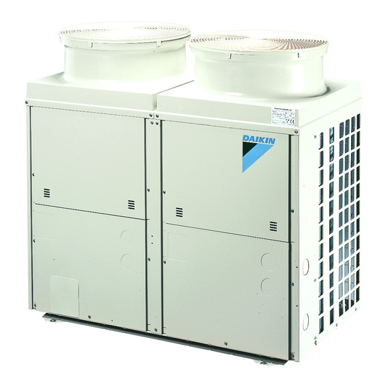
Summary of Contents for Daikin RP200B8W1
-
Page 1: Installation Manual
INSTALLATION MANUAL Split System air conditioners RP200B8W1 RP250B8W1 RYP200B8W1 RYP250B8W1... - Page 2 H ≤ 1500 ⇒ A ≥ 500 h ≤ 500 ⇒ B1 ≥ 300 H = 1500+X ⇒ A ≥ 500+X/2 ⇒ B1 ≥ 300+Y/2 h = 500+Y ≥10 ≥10 ≥10 ≥20 ≥20 ≥10 (mm) H ≤ 1500 ⇒ A ≥ 500 h ≤...
- Page 3 2PW34723-5B...
- Page 4 2PW34723-5B...
-
Page 5: Table Of Contents
OTHER DAMAGE TO THE EQUIPMENT. BE SURE ONLY At delivery, the package should be checked and any damage should TO USE ACCESSORIES MADE BY DAIKIN WHICH ARE be reported immediately to the carrier claims agent. SPECIFICALLY DESIGNED FOR USE WITH THE... -
Page 6: Selecting Installation Site
In accordance with the foundation drawing in the figure, fix the ELECTING INSTALLATION SITE unit securely by means of the foundation bolts. (Prepare four sets of M12 foundation bolts, nuts and washers each which are available on the market.) Make sure to provide for adequate measures in order It is best to screw in the foundation bolts until their length are to prevent that the outdoor unit be used as a shelter 20 mm from the foundation surface. -
Page 7: Precautions On Refrigerant Piping
Allowable pipe length Installation of refrigerant piping is possible as front connection, side connection and bottom connection. See the table below concerning lengths and heights. Refer to figures 2~5. Assume that the longest line in the figure corresponds with the actual longest pipe, and the highest unit in the figure corresponds with the actual highest unit. -
Page 8: Evacuating
In case of simultaneous operation system NOTE Refer to the table for stop valve tightening Upward and downward piping should be performed at the main torques. piping line. Be sure to use both a spanner and a torque Use branch piping kit (optional) for branching refrigerant pipes. wrench when connecting or disconnecting pipes Precautions to be taken. -
Page 9: Charging Refrigerant
Leak test Pair system: refer to figure 2 Evacuate the pipes and check vacuum. (No pressure increase for 1 minute.) L1 (m) one way length of liquid pipe Break the vacuum with a minimum of 2 bar of nitrogen. RP200 G=(L1–30)x0.06 Conduct leak test by applying soap water, etc. -
Page 10: Electrical Wiring Work
LECTRICAL WIRING WORK EST OPERATION All wiring must be performed by an authorized electrician. For the test run procedure, refer to the indoor unit installation manual. All components procured on the site and all electric construction should comply with the applicable local and national codes. ISPOSAL REQUIREMENTS Be sure to use a dedicated power circuit. - Page 11 SD......SAFETY DEVICES INPUT OTES TC......SIGNAL TRANSMISSION CIRCUIT X1M ....... TERMINAL STRIP Y1R......4-WAY VALVE A3P......PRINTED CIRCUIT BOARD DS2......SELECTOR SWITCH (VARIOUS: SEE PCB) DS3......SELECTOR SWITCH (EMERGENCY) HAP ....... LIGHT EMITTING DIODE (GREEN) H1P,H2P ....LIGHT EMITTING DIODE (RED) R3T......
- Page 12 NOTES NOTES...
- Page 13 3 N~ 50 Hz 400 V...
- Page 14 4PW23688-1B Zandvoordestraat 300, B-8400 Oostende, Belgium...


