
Related Manuals for QUANTA D51BP-1U


Summary of Contents for QUANTA D51BP-1U
- Page 1 QuantaGrid Series D51BP-1U Energy Efficient 2-Socket Server with Extreme Storage IOP/S User’s Guide Version: 1.0...
- Page 2 OPYRIGHT Copyright Copyright © 2015 Quanta Computer Inc. This publication, including all photographs, illus- trations and software, is protected under international copyright laws, with all rights reserved. Neither this guide, nor any of the material contained herein, may be reproduced without the express written consent of the manufacturer.
-
Page 3: Table Of Contents
About the System Introduction ............1-1 Package Contents . - Page 4 ONVENTIONS Conventions Several different typographic conventions are used throughout this manual. Refer to the following examples for common usage. Bold type face denotes menu items, buttons and application names. Italic type face denotes references to other sections, and the names of the folders, menus, programs, and files.
-
Page 5: Precautionary Measures
RECAUTIONARY EASURES Precautionary Measures Read all caution and safety statements in this document before performing any of the instructions. To reduce the risk of bodily injury, electrical shock, fire, and equipment dam- age, read and observe all warnings and precautions in this chapter before installing or maintaining your system. -
Page 6: Intended Application Uses
RECAUTIONARY EASURES Table 1: Warning and Cautions (Continued) The enclosure is designed to carry only the weight of the system sled. Do not use this equipment as a workspace. Do not place additional load onto any equipment in this system. Indicates two people are required to safely handle the system. -
Page 7: Equipment Handling Practices
RECAUTIONARY EASURES Equipment Handling Practices Reduce the risk of personal injury or equipment damage: Conform to local occupational health and safety requirements when moving and lifting equipment. Use mechanical assistance or other suitable assistance when moving and lifting equipment. -
Page 8: Rack Mount Warnings
RECAUTIONARY EASURES Rack Mount Warnings The following installation guidelines are required by UL for maintaining safety compliance when installing your system into a rack. The equipment rack must be anchored to an unmovable support to prevent it from tip- ping when your system or piece of equipment is extended from it. The equipment rack must be installed according to the rack manufacturer's instructions. -
Page 9: Cooling And Airflow
RECAUTIONARY EASURES Electrostatic Discharge (ESD) CAUTION! CAN DAMAGE DRIVES BOARDS AND OTHER PARTS E RECOMMEND THAT YOU PERFORM ALL PROCEDURES AT AN WORKSTATION F ONE IS NOT AVAILABLE PROVIDE SOME PROTECTION BY WEARING AN ANTI STATIC WRIST STRAP ATTACHED TO CHASSIS GROUND ANY UNPAINTED METAL SURFACE ON YOUR SERVER WHEN HANDLING PARTS... -
Page 10: General Information
RECAUTIONARY EASURES ified in this manual. Use of other products / components will void the UL listing and other regulatory approvals of the product and will most likely result in non-compliance with product regulations in the region(s) in which the product is sold. System power on/off: To remove power from system, you must remove the system from rack. - Page 11 RECAUTIONARY EASURES Assembly Safety Guidelines The power system in this product contains no user-serviceable parts. Refer servicing only to qualified personnel. The system is designed to operate in a typical office environment. Choose a site that is: Clean and free of airborne particles (other than normal room dust). ...
-
Page 12: Structure Of This Guide
RECAUTIONARY EASURES Structure of this guide Chapter 1: About the System “This section introduces the system, its different configuration(s) and the main features.” Chapter 2: Regulatory and Compliance Information “This section provides regulatory and compliance information applicable to this system.”... -
Page 13: About The System
About the System Chapter 1 This section introduces the system, its different configuration(s) and the main features. -
Page 14: Introduction
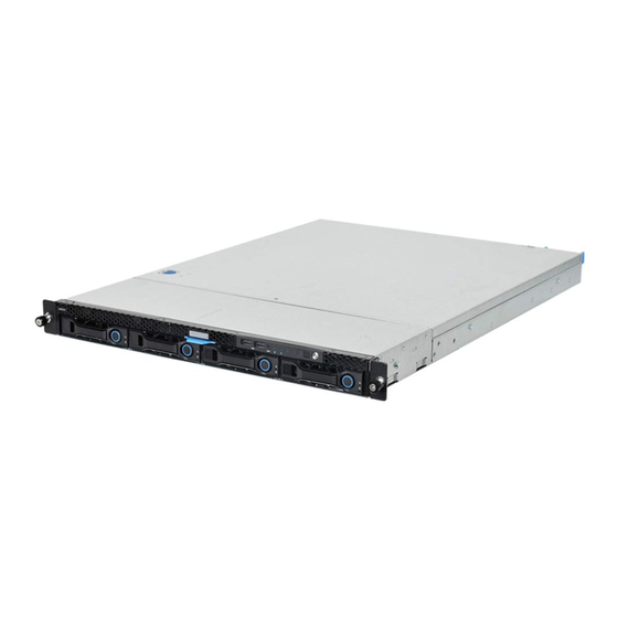
YSTEM NTRODUCTION 1.1 Introduction QuantaGrid D51BP-1U is a revolutionary 1U rackmount server that dramatically increases data storage IOPS. All ten 2.5” front-access drive bays support hot-pluggable SATA/SAS/ PCIe I/O interface. Owners can tailor system storage architecture by mixing traditional hard disk drives and Non-Volatile Memory Express (NVMe) SSD. - Page 15 Quanta LSI® 2308 6Gb/s SAS mezzanine, RAID 0, 1, 10 Quanta LSI® 3008 12Gb/s SAS mezzanine, RAID 0, 1, 10 Quanta LSI® 2208 6Gb/s RAID mezzanine, RAID 0, 1, 5, 10; RAID 6 with additional RAID key LOM: ...
- Page 16 BOUT THE YSTEM NTRODUCTION Table 1.1: System Specifications (Continued) PECIFICATIONS ESCRIPTION 2x USB 3.0 ports 1x VGA port 1x RS232 serial Port Rear I/O 2x 1 GbE or 10G BASE-T RJ45 port 1x GbE RJ45 management port ...
-
Page 17: Package Contents
(1) D51BP-1U system (2) processor heat sinks (1) power supply unit (1) power cord (optional) (1) utility CD (This Guide included) (1) rail kit Note: Note: For exact shipping contents, contact your Quanta sales representative. -
Page 18: A Tour Of The System
BOUT THE YSTEM OUR OF THE YSTEM 1.3 A Tour of the System System Overview The system overview is displayed in the following image: Figure 1-1. System Component Overview Table 2: Component Overview ESCRIPTION Fan module (6) System fan modules DIMM slots (10) DDR4 DIMM slots PSU assembly... -
Page 19: System Front View
BOUT THE YSTEM YSTEM RONT Note: The system features one standard PCIe Riser Assembly supporting standard PCIe cards (see item 4 in previous illustration) and one low profile PCIe riser assembly (available in certain models) supporting low profile PCIe cards (see item 5 in previous illustration). System Front View Figure 1-2. -
Page 20: System Rear View
BOUT THE YSTEM YSTEM Table 4: Front Control Panel Definition (Continued) ESCRIPTION Fault LED Provides critical and non-critical failure notification Identification LED Activate ID LED to identify system ID button Toggles ID LED Power button Power on / off System Rear View Figure 1-4. -
Page 21: Power Sub-System
BOUT THE YSTEM YSTEM Table 6: System Rear I/O Defintition ESCRIPTION OCP connector OCP debug connector (optional) Maximum display resolution: 1920x1200 32bpp@60Hz VGA connector (reduced blanking) COM port A DB9 port (Serial_A) for debug or terminal concentrator NIC2 RJ45 connector NIC1 RJ45 connector Dedicated NIC... -
Page 22: Led Status Definitions
LED S BOUT THE YSTEM TATUS EFINITIONS LED Status Definitions Front Control Panel LED For further information and location of the FCP LEDs, see Front Control Panel LED on page 1-9. Figure 1-7. Front Control Panel LEDs Table 8: Front Control Panel LED Behavior OLOR ONDITION ESCRIPTION... -
Page 23: Lan Led
LED S BOUT THE YSTEM TATUS EFINITIONS LAN LED The system mainboard includes an optional dual 1GbE network with 1GbE dedicated management port with an optional 10G SPF+ OCP network mezzanine card. Each RJ45 connector has two built-in LEDs. See the following illustration and table for details. Activity Link PIN 1... - Page 24 LED S BOUT THE YSTEM TATUS EFINITIONS Table 11: HDD LED Status Behavior (Continued) OLOR ONDITION ESCRIPTION HDD access is active HDD Activity Blue No access HDD failure HDD Fault Amber No failure detected * Only support SATA/SAS HDD/SSD. 1-11...
-
Page 25: Regulatory And Compliance Information
Regulatory and Compliance Information Chapter 2 This section provides regulatory and compliance information applicable to this system. - Page 27 ...
- Page 28 ...
- Page 30 ...
- Page 31 ...
- Page 32 この裝置は、クラス A 情報技術裝置です。この裝置を家庭環境で使用すると電波 妨害を引き起こすことがあります。この場合には使用者が適切な対策を講ずるよう 要求されることがあります。 VCCI-A 警告使用者: 此為甲類資訊技術設備,於居住環境使用中時,可能會造成 射頻擾動,在此種情況下,使用者會被要求採取某些適當的 對策。...
- Page 33 この裝置は、クラス A 情報技術裝置です。この裝置を家庭環境で使用すると電波妨害を引き起こすことがあります。この場合に は使用者が適切な対策を講ずるよう要求されることがあります。 VCCI-A 警告使用者: 此為甲類資訊技術設備,於居住環境使用中時,可能會造成射頻擾動,在此種情況下,使用者會被要求採取某些 適當的對策。...
- Page 34 ...