Table of Contents
Advertisement
SERVICE MANUAL
SERVICE MANUAL
Washing machine 2006
Washing machine 2006
MOON
MOON
All the parts included in this document are the property of Indesit Company S.p.A.
All rights reserved. This document and all the information contained in it are supplied without responsibility
for possible errors or omissions and no part of it can be reproduced, used or removed without written
permission or a contractual clause.
Service Manual
MOON - 2006
Edition
2006.06.12
G
B
Linguage
English
Advertisement
Table of Contents

Related Manuals for Indesit MOON 2006


Summary of Contents for Indesit MOON 2006
-
Page 1: Service Manual
MOON MOON All the parts included in this document are the property of Indesit Company S.p.A. All rights reserved. This document and all the information contained in it are supplied without responsibility for possible errors or omissions and no part of it can be reproduced, used or removed without written permission or a contractual clause. - Page 2 CONTENTS OF THE MANUAL: NOTE FOR THE ENGINEER. This manual is a supporting document for technical personnel. It contains a description of the various product types, the general operating principles and indications concerning assistance. Technical personnel should, in any case, consult the specifi c model on (servicenet.
-
Page 3: Table Of Contents
CONTENTS 1. PRODUCT TYPE Interfaces Technical data Energy Label 2. OPERATING LOGIC 7-13 Innovative product characteristics Instructions for settings and operation 10-11 Programmes 12-13 3. COMPONENTS 4. WIRING DIAGRAMS 5. ASSISTANCE 16-25 Demo Mode Autotest (Testing / Running-in) Autotest Sequence Faults and Solutions 17-19 Doctor... -
Page 4: Product Type
Product line Brand Type Type Max Spin Speed Specs Colour S = Smart I = Indesit X = maxi 6 kg. L = led 8 = 800 S = silver unit S = Slim D = display 10 = 1000... -
Page 5: Interfaces
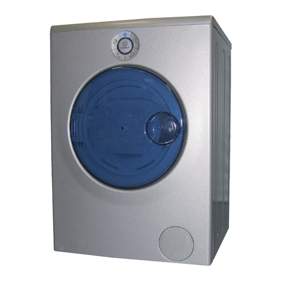
1.2. INTERFACE: 1. On/OFF/RESET BUTTON 6. Rapid 30’/Rinse Only/PAUSE BUTTON 2. DOOR LOCK 7. Programme PROGRESS RING 3. Cotton Whites/PAUSE BUTTON 8. Door 4. Mixed Coloureds Easy Iron/PAUSE BUTTON 9. Filter Cover 5. Delicates/PAUSE BUTTON 1.3. TECHNICAL DATA: MODEL: MOON Capacity: da 1 a 6,0 Kg Dimensions:... -
Page 6: Energy Label
1.3. ENERGY LABEL: E n e r g y Washing machine INDESIT Brand Manufacturer Model Model MOON More efficient Power Class Less efficient Power Consumption in standard cycle 1.02 Energy c on s um p ti on (kW/h) kWh/cy c l e (ba s e d o n s t a n d a r d t e s t r e s u l t s f o r 60°... -
Page 7: Operating Logic
2. OPERATING LOGIC: 2.1. PRODUCT CHARACTERISTICS AND TECHNOLOGICAL INNOVATIONS: The MOON washing machine features many technological innovations, which are listed below: Drain pump Programme selector Conductivity sensor Water system Detergent dispenser Door seal / Door Detailed explanation of these components is provided below. -
Page 8: Detergent Dispenser
DETERGENT DISPENSER: The detergent dispenser is located inside the appliance, on the inside of the door. It can be removed for cleaning by lifting it upwards and carefully releasing the top cover. The dispenser consists of three compartments: the fi rst (left to right) is for liquid detergents. The second (middle compartment) is for powder detergents, while the last (right-hand) is for fabric softener. -
Page 9: Drain Pump
DRAIN PUMP: A plastic cover has been fi tted on the fi lter to prevent hands from coming into contact with the electrical The drain pump is equipped with a new self-cleaning part of the pump, which must not be eliminated. bayonet fi... -
Page 10: Instructions For Settings And Operation
2.2. APPLIANCE OPERATION: SWITCHING THE APPLIANCE ON/OFF: The machine is switched on by pressing the On button. The symbol on the button lights up, after which the programme buttons start fl ashing and the leds on the ring light up one after another. At this point the machine is on Stand By and is ready for use. -
Page 11: Programme Progress
RESETTING A PROGRAMME IN PROGRESS: To reset a programme in progress, press and hold the On button for more than 1 second. The washing machine will switch off and the programme in progress will be cancelled. Before switching off, the washing machine automatically runs a drain cycle, whether there is water in the drum or not. -
Page 12: Programmes
2.3. PROGRAMMES: The wash cycle selection buttons correspond to the following wash programmes: • Cotton Whites: Standard 60° cotton wash cycle. (Spin 1200 rpm) • Mixed coloureds/Easy Iron: Wash cycle suitable for garments of mixed colours in cotton or synthetic fabric, with a wash temperature of 40°. -
Page 13: Programme Table
2.3.4 PROGRAMME TABLE Spin Fabrics Max load Duration Wash cycle Temperature speed description (kg) (rpm) WHITES COTTON Wash, rinses, intermediate Hard-wearing white cotton and final spin cycles MIXED COLOUREDS Wash, rinses, Coloured cottons and synthetics delicate spin cycle DELICATES Wash, rinses, delicate spin cycle Wool, silk and other delicates (wool) or drain (silk) RAPID/RINSE ONLY... -
Page 14: Components
3. COMPONENTS: Display PCB. Oko System. Detergent dispenser. Water Distributor. Washing machine door. Conductivity Sensor. Drain Pump Filter. Vent tube. Service Manual Edition Linguage MOON - 2006 2006.06.12 English... -
Page 15: Wiring Diagrams
4. WIRING DIAGRAMS: Service Manual Edition Linguage MOON - 2006 2006.06.12 English... -
Page 16: Assistance
5. ASSISTANCE: 5.1. DEMO MODE: This machine does not feature the Demo Mode function. 5.2. AUTO TEST: The Hardware Key (transparent - C0095669) is used to run the EVOII platform Autotest program. A BLUE led will light up on the hardware key to indicate that the appliance is an EVOII machine. A fl... -
Page 17: Faults And Solutions
5.3. ANALYSIS AND SOLUTION OF LED 1 FAULTS: SYMBOLS: LED 5 LED 2 fl ashing led LED 4 LED 3 led off LED COMBINATION FAULT CAUSE TEMPERATURE LED Motor driving triac short-circuit LED 5 LED 4 LED 3 LED 2 LED 1 Motor tripped, motor tacho LED 5... - Page 18 Fault indication leds fl ash together with programme button leds. FAULT CAUSE CORRECTIVE ACTIONS - Check for water leaks that may affect connector J9 causing the relative contacts to short; Motor driving triac short- - Check the motor terminal board (any problems due to aggression circuit caused by manufacturing chemical residues may cause short- circuits);...
- Page 19 FAULT CAUSE CORRECTIVE ACTIONS Wash heating element - Check effi ciency of contacts on connector J3 on PCB; relay contacts sticking - Check condition of pressure switch by checking for impedance on (signalled in presence J3 wiring connector pins 2 and 4 (impedance should be measured of empty condition) or only with tub empty), pins 2 and 3 (impedance should be measured pressure switch sticking on...
-
Page 20: Doctor
5.4. DOCTOR: The appliance has a main PCB, located at the rear right hand side and protected by a plastic cover. Always replace the cover after removing it to connect the Hardware key. The Hardware key is used for fault diagnosis or to update PCB software if necessary. -
Page 21: Dismantling/Assembly
5.5 DISMANTLING/ ASSEMBLY: Removing the door seal: 4. Remove the door seal from its seat. 1. Open the door. 2. Remove the outer tub seal between the door 5. Remove the two clamps securing the water inlet and the front. hoses, then remove the hoses. - Page 22 Dismantling the display PCB 1. Unplug the appliance from the mains power supply and remove the top panel from the washing machine. 2. Remove the screw securing the control panel 5. Using the same screwdriver, prise the tabs 3. Disconnect the connector from the display PCB. securing the display PCB to the front, pushing the central disc to remove it.
- Page 23 Dismantling the detergent dispenser 3. Remove the 5 hooks (2 at the front, 3 at the rear) 1. Open the door. that secure the dispenser plug. 4. Remove the fl oats by lifting them upwards. 2. Pull the detergent drawer upwards. Dismantling the conductivity sensor 3.
- Page 24 Dismantling the vent tube 1. Remove the top of the washing machine. 3. Grip the end of the vent tube where it is connected to the tub, pushing gently towards the front of the machine. 2. Insert a fl at blade screwdriver next to the hooks and push outwards.
- Page 25 Dismantling the door 1. Open the door. 4. Insert a fl at blade screwdriver between the handle and the edge of its seat, taking care not to damage or scratch the plastic cover. 2. Unscrew the two screws securing the door to the hinge.
- Page 26 6. Gripping the door with both hands, exert enough pressure to separate it from its cover. 7. Inserting a screwdriver into one of the recesses, prise off the handle. 8. To complete the door dismantling procedure, remove the door lock support pin with a pair of pliers.
-
Page 27: Exploded Views
6. EXPLODED VIEWS: APPLIANCE BODY. Ref. description Ref. description SMART DISPENSER COVER GREY FILTER COVER MOON RIGHT LEVEL INDICATOR ADJUSTABLE FOOT M8 H = 2.3 CM DETERGENT DRAWER RIGHT SIPHON FOOT SPRING D =11 MM H = 8.5 DETERGENT DRAWER LEFT SIPHON SCREW M4.5 X 11 TIMER AND DOOR/HINGE SMART DETERGENT DISPENSER DRAIN HOSE COLLAR ’AB636TX’... - Page 28 MOBILE ASSEMBLY. Rif. Rif. Ref. descrizione descrizione description Rif. Rif. Ref. descrizione descrizione description SCREW X COUNTERWEIGHT/AQUALT. TUB AQUALTIS FLEXIBLE DRAIN HOSE TOP COUNTERWEIGHT VPL 12.5 KG AQUAL. HOSE CLAMP - DRAIN PUMP SIDE AQUALTIS SPRING RING NUT REMOVABLE DRUM BAFFLE 46L SMART TUB SPRING GASKET FOR OKO AQUAL FLEXIBLE DRAIN HOSE PLASTIC TUB UNIT 52 L H=20 MM SMART...
- Page 29 ELECTRICAL AND ELECTRONIC COMPARTMENTS. HARDWARE Rif. Rif. Ref. descrizione descrizione description Rif. Rif. Ref. descrizione descrizione description 001 THREE-LOBED SELF-TAPPING SCREW 3.5X8 DENT 015 ASKOLL/PLASET BAYONET PUMP FILTER KIT 002 POWER SUPPLY CABLE .3X1 SCHUKO 1.5M+IND. FILTER 016 NTC TEMPERATURE SENSOR 003 WASHER-DRYER DRAIN PUMP 017 HEATING ELEMENT 1700/230 VPL 004 CONTROL UNIT NO SMART PCB...
- Page 30 1.00 X BROWN 0.35 X 1390 1.00 X white BLUE 0.35 X 1390 white 0.50 X 1250 celeste 0.35 X 1390 1.00 X 1250 BLUE 0.35 X 1390 1.00 X 1250 light blue BROWN 1.00 X 1250 BLUE 1.00 X BROWN R.TF.
- Page 31 Indesit Company viale Aristide Merloni, 47 60044 Fabriano - Italy tel. +39 0732 66 11 - telex 560196 - fax +39 0732 66 2954 - www.indesitcompany.com Service Manual Edition Linguage MOON - 2006 2006.06.12 English...