Advertisement
Table of Contents
- 1 Table of Contents
- 2 Specifications
- 3 Precautions
- 4 Installation Instructions
- 5 Wiring Instructions
- 6 4-Channel and Mixed-Mono Input Wiring Diagram
- 7 4-Channel and Mixed-Mono Output Wiring Diagram
- 8 3-Channel and Mixed-Mono Input Wiring Diagram
- 9 3-Channel and Mixed-Mono Output Wiring Diagram
- 10 2-Channel and Mixed-Mono Input Wiring Diagram
- 11 2-Channel and Mixed-Mono Output Wiring Diagram
- 12 Operation
- 13 Warranty
- Download this manual
Advertisement
Table of Contents

Summary of Contents for Audiovox Rampage AXT-500
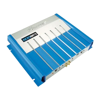
- Page 1 Model AXT-500 500 Watt 4-Channel Bridgeable MOSFET Amplifier OWNER'S MANUAL...
-
Page 2: Table Of Contents
INDEX Specifications...3 Precautions...4 Installation Instructions... 5 Wiring Instructions... 6 - 7 4-Channel and Mixed-Mono Input Wiring Diagram... 8 4-Channel and Mixed-Mono Output Wiring Diagram... 9 3-Channel and Mixed-Mono Input Wiring Diagram...10 3-Channel and Mixed-Mono Output Wiring Diagram... 11 2-Channel and Mixed-Mono Input Wiring Diagram...12 2-Channel and Mixed-Mono Output Wiring Diagram... -
Page 3: Specifications
10 - 35KHz. +/-1 dB Channel Separation: 60 dB Signal / Noise Ratio: 90 dB (A-Weighted) * Due to continuing improvement, Audiovox reserves the right to change features and design without notice. HELP! 1-800-645-4994 Monday-Friday 8:30am - 7:00pm Eastern Saturday... -
Page 4: Precautions
6. Make certain that the speaker(s) to be used with this amplifier are capable of handing the output power (wattage) of the unit. Use of speaker(s) not rated for the output of this amplifier may cause damage to or failure of the speaker(s) for which Audiovox will not be liable. -
Page 5: Installation Instructions
INSTALLATION INSTRUCTIONS 1. Select a mounting area where the amplifier will have sufficient air circulation for proper cooling. Inadequate air circulation will cause the temperature of the amplifier to rise and will trigger the thermal protection mode. 2. Place the amplifier on the mounting surface and mark the locations of the four mounting holes as shown in the illustration. -
Page 6: Wiring Instructions
WIRING INSTRUCTIONS The wiring of your amplifier will depend on the system and speakers you are using but will either be a stereo, mono, or mixed-mono application. The following pages illustrate the input and output wiring for these types. please refer to the appropriate diagrams for the system configuration you are using. - Page 7 WIRING INSTRUCTIONS 4. Speaker Connections Depending on the type and number of speakers used with the amplifier, wire them to the speaker terminals as per the appropriate wiring diagram. For most applications, #16 gauge wire should be used for the speaker leads but in no case thinner than #18 gauge.
-
Page 8: 4-Channel And Mixed-Mono Input Wiring Diagram
4-CHANNEL AND MIXED-MONO INPUT WIRING DIAGRAM LOW-LEVEL RCA OUTPUTS Left Rear CAR STEREO Right Rear Right Front Left Front IMPORTANT USE EITHER HIGH-LEVEL OR LOW-LEVEL INPUT, NOT BOTH. RCA TYPE SHIELED CABLES (NOT INCLUDED) TO CH1 TO CH2 TO CH4 TO CH3 X-OVER X-OVER... -
Page 9: 4-Channel And Mixed-Mono Output Wiring Diagram
4-CHANNEL AND MIXED-MONO OUTPUT WIRING DIAGRAM LEFT RIGHT SPEAKER SPEAKER LEFT REAR SPEAKER BRIDGED BRIDGED BRIDGED BRIDGED CH1 / CH2 CH3 / CH4 MIXED-MONO SPEAKER OR MIXED-MONO SPEAKER OR SUB-WOOFER WITH CROSSOVER SUB-WOOFER WITH CROSSOVER 4-8 OHMS 4-8 OHMS GROUND CAR STEREO BATTERY FOR 12 VOLT USE ONLY... -
Page 10: 3-Channel And Mixed-Mono Input Wiring Diagram
3-CHANNEL INPUT WIRING DIAGRAM CAR STEREO LOW-LEVEL RCA OUTPUTS Mono or Sub-Woofer Right Left IMPORTANT USE EITHER HIGH-LEVEL OR LOW-LEVEL INPUT, NOT BOTH. RCA TYPE SHIELED CABLES (NOT INCLUDED) TO CH1 TO CH2 TO CH3 / CH4 X-OVER X-OVER FULL FULL 50Hz 50Hz... -
Page 11: 3-Channel And Mixed-Mono Output Wiring Diagram
SPEAKER IMPEDANCE 4-CHANNEL MODE: 2-8 OHMS 2/3-CHANNEL MODE: 4-8 OHMS LEFT FRONT RIGHT FRONT SPEAKER SPEAKER BRIDGED BRIDGED BRIDGED BRIDGED MONO SPEAKER SUB-WOOFER 4-8 OHMS GROUND CAR STEREO BATTERY FOR 12 VOLT USE ONLY 3-CHANNEL OUTPUT WIRING DIAGRAM EXISTING SCREW OR BOLT CLEAN PAINT, RUST, DIRT OR GREASE FROM AREA FOR GOOD CONNECTION. -
Page 12: 2-Channel And Mixed-Mono Input Wiring Diagram
2-CHANNEL MONO (BRIDGED) INPUT WIRING DIAGRAM CAR STEREO LOW-LEVEL RCA OUTPUTS Right Left IMPORTANT USE EITHER HIGH-LEVEL OR LOW-LEVEL INPUT, NOT BOTH. RCA TYPE SHIELED CABLES (NOT INCLUDED) TO CH1 / CH2 TO CH3 / CH4 X-OVER X-OVER FULL FULL 50Hz 50Hz HIGH-LEVEL... -
Page 13: 2-Channel And Mixed-Mono Output Wiring Diagram
2-CHANNEL MONO (BRIDGED) OUTPUT WIRING DIAGRAM LEFT SPEAKER SUB-WOOFER 4-8 OHMS BRIDGED BRIDGED BRIDGED BRIDGED GROUND CAR STEREO BATTERY FOR 12 VOLT USE ONLY EXISTING SCREW OR BOLT CLEAN PAINT, RUST, DIRT OR GREASE FROM AREA FOR GOOD CONNECTION. RIGHT SPEAKER SUB-WOOFER 4-8 OHMS FUSE... -
Page 14: Operation
OPERATION HI-INPUT HI-INPUT X-OVER X-OVER FULL FULL 50Hz 50Hz 250Hz 250Hz GAIN GAIN GAIN GAIN After initial set-up, the amplifier should not require any further adjustment unless there is a change in the car stereo or speaker system with which it is used. Power Indicator Lamps The Power Indicator Lamps will light to indicate that the unit is connected to the battery and that the Remote... - Page 15 from the system. If, however, there is still output from the amplifier when the car stereo volume control is at its minimum setting, or the output level increases too fast with a small rotation of the volume control, adjust the Level control to decrease the output from the system.
-
Page 16: Warranty
AUDIOVOX CORPORATION (the Company) warrants to the original retail purchaser of this product that should this product or any part thereof, under normal use and conditions, be proven defective in material or workmanship within 90 days from the date of original purchase, such defect(s) will be repaired or replaced with new or reconditioned product (at the Company's option) without charge for parts and repair labor. - Page 17 2003 Audiovox Electronics Corporation, Hauppauge, N.Y. Printed in Korea 128-6561 1...


