
Related Manuals for Audiovox Rampage AMP-610


Summary of Contents for Audiovox Rampage AMP-610
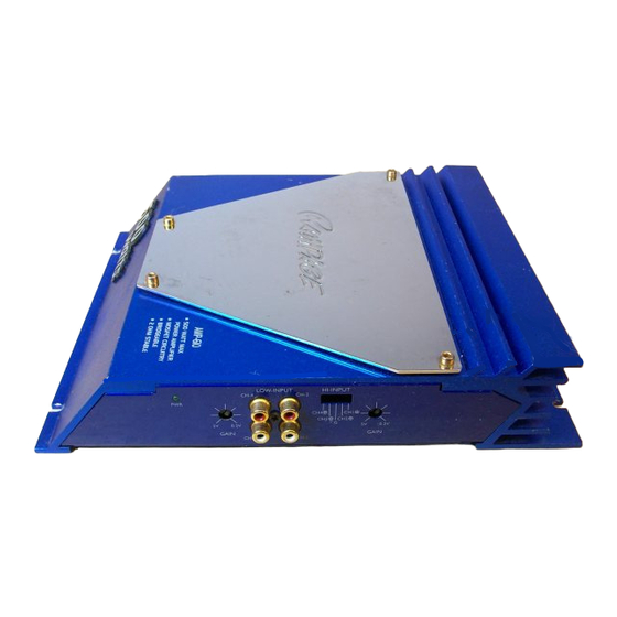
- Page 1 Model AMP-610 500 Watt Stereo Amplifier Ow ne ne ne ne ne r's Manual Manual Manual Manual Manual...
-
Page 2: Table Of Contents
INDEX Specifications ...1 Precautions ...2 Installation Instructions ...3 Controls and Indicators...4 - 7 Wiring Instructions ...7 4-Channel and Mixed -Mono Input Wiring Diagram ...8 4-Channel and Mixed -Mono Output Wiring Diagram ...9 3-Channel Input Wiring Diagram ...10 3-Channel Output Wiring Diagram Wiring Diagram ...11 2-Channel Mono (Bridged) Input Wiring Diagram ...12 2-Channel Mono (Bridged) Output Wiring Diagram ...13 Warranty ...14... -
Page 3: Specifications
Frequency Response: 10 - 50,000 Hz. ± 1 dB Channel Separation: 55 dB * Due to continuing improvement, Audiovox reserves the right to change features and design without notice. HELP! 1-800-645-4994 Monday - Friday S a t u r d a y... -
Page 4: Precautions
6. Make certain that the speaker(s) to be used with this amplifier are capable of handling the output power (wattage) of the unit. Use of speaker(s) not rated for the output of this amplifier may cause damage to or failure of the speaker(s) for which Audiovox will not be liable. -
Page 5: Installation Instructions
INSTALLATION INSTRUCTIONS 1. Select a mounting area where the amplifier will have sufficient air circulation for proper cooling. Inadequate air circulation will cause the temperature of the amplifier to rise and will trigger the thermal protection mode. 2. Place the amplifier on the mounting surface and mark the locations of the four mounting holes as shown in the illustration. -
Page 6: Controls And Indicators
CONTROLS AND INDICATORS... - Page 7 Power Indicator/Protection Mode LED The Power Indicator LED will light to indicate that the unit is connected to the battery and that the Remote Turn-On terminal is receiving +12 volts, thus turning on the amplifier. This LED illuminates red to indicate that the self-protection circuits have been activated and have shut off operation of the amplifier. The protection circuits may be triggered by the temperature of the unit rising above a safe level or by an overload condition.
- Page 8 High Level Input Connection If the car stereo does not provide low-level outputs, the amplifier may be connected via the speaker (high-level) outputs from the stereo. Wire the speaker leads from the car stereo to the 5-pin adaptor harness as shown in the diagram (shielded cable is not required for this application) and plug the connector into the mating High-Level Input socket on the amplifier.
-
Page 9: Wiring Instructions
provide an Auto-Antenna lead, the remote turn-on lead may be wired to an "Accessory" or "Radio" terminal in the car's fuse block. This will turn the amplifier on and off with the ignition key, regardless of whether the car stereo is on or off. The remote turn-on lead does not carry large currents, so #20 gauge wire may be used for this application. -
Page 10: 4-Channel And Mixed-Mono Input Wiring Diagram
4-CHANNEL AND MIXED-MONO INPUT WIRING DIAGRAM LOW-LEVEL CAR STEREO RCA OUTPUT RIGHT FRONT LEFT FRONT RIGHT REAR LEFT REAR IMPORTANT USE EITHER HIGH-LEVEL OR LOW-LEVEL INPUTS, NOT BOTH. RCA TYPE SHIELDED CABLES (NOT INCLUDED) HIGH-LEVEL (SPEAKER) OUTPUTS RIGHT REAR + LEFT REAR + RIGHT FRONT + LEFT FRONT +... -
Page 11: 4-Channel And Mixed-Mono Output Wiring Diagram
USE THIS OUTPUT WIRING WITH INPUT WIRING ON PAGE 8 EXISTING SCREW OR BOLT CLEAN PAINT, RUST, DIRT OR GREASE FROM AREA FOR GOOD CONNECTION GROUNDED METAL SECTION OF VEHICLE CONNECT THIS WIRE LAST 12 VOLT VEHICLE BATTERY CHASSIS GROUND CAR STEREO AUTO-ANTENNA LEAD 4-CHANNEL AND MIXED-MONO OUTPUT WIRING DIAGRAM... -
Page 12: 3-Channel Input Wiring Diagram
3-CHANNEL INPUT WIRING DIAGRAM HIGH-LEVEL (SPEAKER) OUTPUTS RIGHT REAR + LEFT REAR + RIGHT FRONT + LEFT FRONT + LOW-LEVEL RCA OUTPUTS CAR STEREO CHASSIS GROUND IMPORTANT ON RADIO USE EITHER HIGH-LEVEL OR LOW-LEVEL INPUTS, NOT BOTH. SHIELDED CABLES 5-PIN CONNECTOR TO CH2 TO CH1... -
Page 13: 3-Channel Output Wiring Diagram Wiring Diagram
USE THIS OUTPUT WIRING WITH GROUNDED METAL INPUT WIRING ON PAGE 10 SECTION OF VEHICLE EXISTING SCREW OR BOLT CLEAN PAINT, RUST, DIRT OR GREASE FROM AREA FOR GOOD CONNECTION USE #10 GAUGE WIRE (SEE TEXT) CONNECT THIS WIRE LAST 12 VOLT VEHICLE BATTERY... -
Page 14: 2-Channel Mono (Bridged) Input Wiring Diagram
2-CHANNEL MONO (BRIDGED) INPUT WIRING DIAGRAM HIGH-LEVEL (SPEAKER) OUTPUTS RIGHT REAR + LEFT REAR + CHASSIS ON RADIO RIGHT FRONT + LEFT FRONT + LOW-LEVEL CAR STEREO RCA OUTPUTS RIGHT LEFT IMPORTANT USE EITHER HIGH-LEVEL OR GROUND LOW-LEVEL INPUTS, NOT BOTH. 5-PIN CONNECTOR W H I T E... -
Page 15: 2-Channel Mono (Bridged) Output Wiring Diagram
USE THIS OUTPUT WIRING WITH INPUT WIRING ON PAGE 12 EXISTING SCREW OR BOLT CLEAN PAINT, RUST, DIRT OR GREASE FROM AREA FOR GOOD CONNECTION GROUNDED METAL SECTION OF VEHICLE CONNECT THIS WIRE LAST 12 VOLT VEHICLE BATTERY CHASSIS GROUND CAR STEREO 2-CHANNEL MONO (BRIDGED) OUTPUT WIRING DIAGRAM LEFT SPEAKER... -
Page 16: Warranty
AUDIOVOX CORPORATION (the Company) warrants to the original retail purchaser of this product that should this product or any part thereof, under normal use and conditions, be proven defective in material or workmanship within 90 days from the date of original purchase, such defect(s) will be repaired or replaced with new or reconditioned product (at the Company's option) without charge for parts and repair labor.