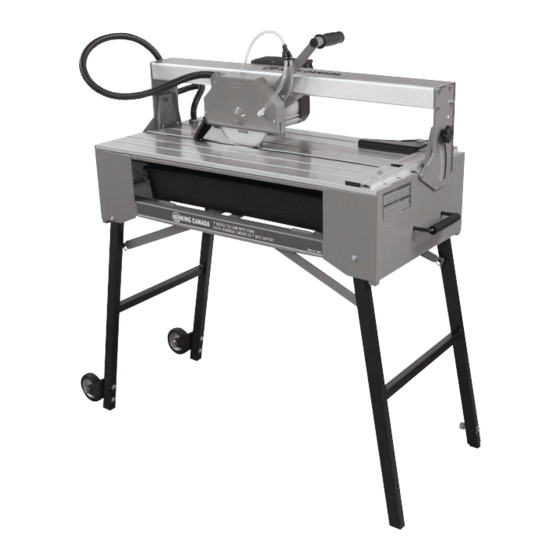
Summary of Contents for King Canada KC-3009
-
Page 1: Instruction Manual
7” BRIDGE TILE SAW WITH STAND 12/2015 INSTRUCTION MANUAL MODEL: KC-3009 COPYRIGHT © 2015 ALL RIGHTS RESERVED BY KING CANADA TOOLS INC. -
Page 2: Warranty Information
King Canada service center. Contact your retailer or visit our web site at www.kingcanada.com for an updated listing of our authorized service centers. In cooperation with our authorized serviced center, King Canada will either repair or replace the product if any part or parts covered under this warranty which examination proves to be defective in workmanship or material during the warranty period. -
Page 3: Safety Instructions
GENERAL & SPECIFIC SAFETY INSTRUCTIONS VOLTAGE WARNING: Before connecting the tool to a power source (receptacle, outlet, etc.) be sure the voltage supplied is the same as that specified on the nameplate of the tool. A power source with voltage greater than that for the specified tool can result in SERIOUS INJURY to the user - as well as damage to the tool. -
Page 4: Electrical Information
ELECTRICAL INFORMATION WARNING ALL ELECTRICAL CONNECTIONS MUST BE DONE BY A QUALIFIED ELECTRICIAN. FAILURE TO COMPLY MAY RESULT IN SERIOUS INJURY! ALL ADJUSTMENTS OR REPAIRS MUST BE DONE WITH THE TILE SAW DISCONNECTED FROM THE POWER SOURCE. FAILURE TO COMPLY MAY RESULT IN SERIOUS INJURY! POWER SUPPLY sons or children can’t turn the switch to the On position. -
Page 5: Getting To Know Your Tile Saw
17. Miter gauge bar lock knob (2 of 2). 26. Water tray (4 gallon capacity) 9. Tilting lock knob (1 of 2). 18. Guide ruler. SPECIFICATIONS Model ......................................KC-3009 Motor ..................................1.5 HP (9.2 Amp.) No load speed..................................3,600 RPM Blade diameter ....................................7” Arbor diameter ....................................5/8”... - Page 6 ASSEMBLY ASSEMBLY & LEVELING OF THE STAND 1. Unpack the tile saw. With the help of another person, position the tile saw on its side on a flat, level surface as shown in Fig.3. 2. Pull out both stand legs (A & B) Fig.3, lower the 4 stand support brackets (C) and at- tach them to the fixed pin (D) on each side of the stand legs.
- Page 7 SET-UP, ADJUSTMENTS & OPERATION SET-UP: BEFORE ATTEMPTING TO USE TILE SAW 1. For shipping and safety reasons, the sliding motor and blade assembly comes locked to the right bridge bracket (B) Fig.6. Remove lock knob (A) and place it in a safe lo- cation, the sliding assembly can now slide back and forth.
- Page 8 ADJUSTMENTS & OPERATION OPERATION: MAKING A STRAIGHT CUT continued... 5. Plug the power cord into the nearest 120 volt, grounded, electrical outlet, making sure power cord will not come in contact with any water. 6. Turn the switch (A) Fig.9 to its “ON” position, and allow the tile saw blade (A) Fig.10 to spin up to full speed.
- Page 9 ADJUSTMENTS & OPERATION OPERATION: MAKING A BEVEL CUT 1. Loosen both lock knobs (A) Fig.12 on each end of the tile saw. 2. Tilt the sliding bridge assembly (B) to the desired angle, use the angle scale and pointer (C) as a guide. Then, retighten both lock knobs (A) Fig.12. Note: To obtain a precise 45 degree setting, it is recommended to use a combination square placed up against the blade to make this adjustment.
-
Page 10: Maintenance
MAINTENANCE MAINTENANCE WARNING: For your own safely, turn switch "OFF" and remove plug from power source outlet before adjusting, maintaining, or lubricating your tile saw. WARNING: To avoid electrocution or fire, any repair to electrical system should be done by qualified service technicians. Unit must be reassembled exactly to factory specifications.


