
Related Manuals for Henny Penny HHC-902


Summary of Contents for Henny Penny HHC-902
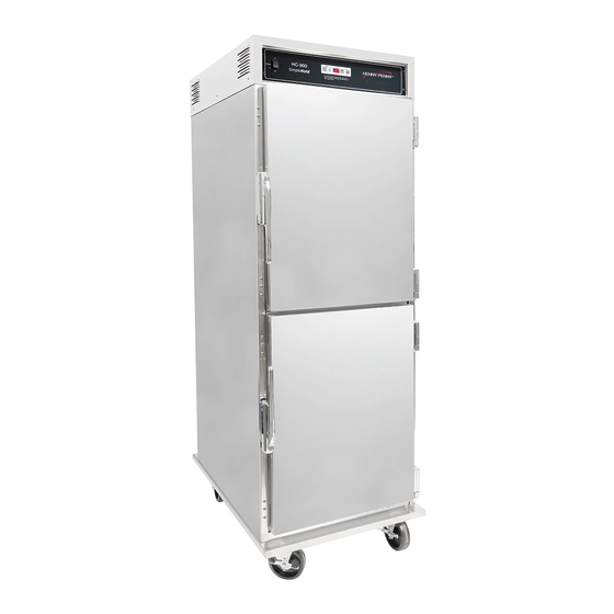
- Page 1 Henny Penny Heated Holding Cabinet Model HHC-900 Model HHC-902 Model HHC-903 Model HHC-906 Model HHC-908 Model HC-15 TECHNICAL MANUAL...
-
Page 3: Table Of Contents
Models HHC-90X/HC-15 TABLE OF CONTENTS Section Page Section 1. TROUBLESHOOTING ..................... 1-1 1-1. Introduction ...................... 1-1 1-2. Safety ....................... 1-1 1-3. Troubleshooting ....................1-1 Section 2. MAINTENANCE ...................... 2-1 2-1. Introduction ...................... 2-1 2-2. Test Instruments ....................2-1 2-3. Removal of Module Access Panel ..............2-1 2-4. -
Page 5: Troubleshooting
Models HHC-90X/HC-15 SECTION 1. TROUBLESHOOTING 1-1. INTRODUCTION This section provides troubleshooting information in the form of an easy to read list. If a problem occurs during the first operation of a new cabinet, recheck the Installation Section of the Operator’s Manual. Before troubleshooting, always recheck the Operation Section of the Operator’s Manual. 1-2. -
Page 6: Troubleshooting
Models HHC-90X/HC-15 1-3. TROUBLESHOOTING (Continued) PROBLEM CAUSE CORRECTION OPERATION A. Product not • Doors are left open • Keep doors closed except to holding load and unload product temperature • Thermostat set too low • Increase thermostat setting by moving the knob to a higher number setting • Gasket torn or worn • Replace gasket per Door Gasket Replacement Section • Heater not working • Check heater; replace per Heater Section • Blower not working... - Page 7 Models HHC-90X/HC-15 1-3. TROUBLESHOOTING (Continued) PROBLEM CAUSE CORRECTION HEATING SYSTEM (Continued) B. Unit will not heat • Faulty blower • Check blower; replace per Blower to desired temp- Section erature • Thermometer not indicating • Check cabinet temperature with true temperature another thermometer; if necessary, replace per Thermometer Section • One of heaters defective • Check heater; replace per Heater Section • Doors being left open too much • Only open doors as necessary • Gaskets torn or worn • Replace gasket per Door Gasket Replacement Section...
-
Page 9: Section 2. Maintenance
Models HHC-90X/HC-15 SECTION 2. MAINTENANCE 2-1. INTRODUCTION This section provides procedures for the testing and replacement of the various parts used within the cabinet. Before replacing any parts, refer to the Troubleshooting Section. It will aid you in deter- mining the cause of the malfunction. 2-2. -
Page 10: Removal Of Module Housing
Models HHC-90X/HC-15 2-5. REMOVAL OF If the need for extensive service is required on the module compo- MODULE HOUSING nents, the entire outer shell of the module can be removed to make servicing easier. To remove the outer shell of the module, follow these procedures: 1. Remove the module from the cabinet per Module Removal Section. -
Page 11: Fuse
Models HHC-90X/HC-15 2-6. FUSE All units are not equipped with fuses. If both blowers quit working at the same time: 1. Remove electrical power supplied to the cabinet. Step 2 To avoid electrical shock or property damage, move the power switch to OFF and disconnect main circuit breaker, or unplug cord at wall receptacle. 2. -
Page 12: Power Switch
Models HHC-90X/HC-15 2-7. POWER SWITCH 1. Disconnect the electrical supply to the cabinet. To avoid electrical shock or property damage, move the power switch to OFF and disconnect main circuit breaker, or unplug cord at wall receptacle. 2. Remove the four (4) screws from the control panel and pull it Step 3 down. -
Page 13: Thermostat
Models HHC-90X/HC-15 2-8. THERMOSTAT 1. Disconnect the electrical supply to the cabinet. To avoid electrical shock or property damage, move the power switch to OFF and disconnect main circuit breaker, or unplug cord at wall receptacle. 2. Remove the access panel from the top of the module. Step 5 3. Remove the four (4) screws from the control panel and pull it down. -
Page 14: Indicating Lights
Models HHC-90X/HC-15 2-8. THERMOSTAT 13. Install a new thermostat in reverse order. (Continued) 14. Reposition the blower box and secure it with the four (4) nuts previously removed. Be sure that both the thermometer and thermostat capillary tubes pass through the notches in the front corners of the blower box. Failure to do so could permanently damage the thermometer or thermostat and cause improper operation of the cabinet. -
Page 15: Thermometer
Models HHC-90X/HC-15 2-9. INDICATING LIGHTS 4. Remove the light by squeezing the retainers on the body and (Continued) pushing the light out through the control panel. 5. Install a new light by pushing it through the front of the con- trol panel until it snaps securely in place. 6. Strip the ends of the cut wires and connect them to the new light with wire nuts. -
Page 16: Heater
Models HHC-90X/HC-15 2-10. THERMOMETER (Continued) Be sure that both the thermometer and thermostat capillary tubes pass through the notches in the front corners of the blower box. Failure to do so could permanently damage the thermometer or thermostat and cause improper operation of the cabinet. -
Page 17: High Limit
Models HHC-90X/HC-15 2-11. HEATER 6. Remove the heater. (Continued) 7. Install a new beater in reverse order. If you have a 240V, 3,000 W unit, you must install the new heater so that the coils are spread furthest apart where air from the blower enters the heater. 8. Reattach the heater wires. 9. -
Page 18: Blower
Models HHC-90X/HC-15 2-12. HIGH LIMIT 6. Remove the high limit. (Continued) 7. Install a new high limit in reverse order. 8. Reconnect the two wires to the high limit. 9. Replace the access panel to the module. 10. Reconnect the electrical supply to the cabinet. 2-13. - Page 19 Models HHC-90X/HC-15 2-13. BLOWER (Continued) The blower motor can be ordered as an assembly. This will include the motor, the fan, and the wheel. Normally, just the motor would need replacing if found to be defective. If you are just replacing the motor, continue with the following procedures.
-
Page 20: Door Gasket Replacement
Models HHC-90X/HC-15 2-14. DOOR GASKET 1. Pull the gasket to the side to expose the screws that hold the REPLACEMENT retainer to the cabinet. 2. Loosen the screws around the full outside perimeter of the gasket. 3. With the screws loose, the gasket should slide out from under the retainer. 4. Remove the gasket and replace with a new one by reversing the above procedures. -
Page 21: Wiring Diagrams
Models HHC-90X/HC-15 2-15. WIRING DIAGRAMS 2-13... - Page 22 Models HHC-90X/HC-15 2-15. WIRING DIAGRAMS (Continued) 2-14...
- Page 23 Models HHC-90X/HC-15 2-15. WIRING DIAGRAMS (Continued) 2-15...
- Page 24 Models HHC-90X/HC-15 2-15. WIRING DIAGRAMS (Continued) 2-16...
- Page 25 Models HHC-90X/HC-15 2-15. WIRING DIAGRAMS (Continued) 2-17...
- Page 26 Models HHC-90X/HC-15 2-15. WIRING DIAGRAMS (Continued) 2-18...
- Page 27 Models HHC-90X/HC-15 2-15. WIRING DIAGRAMS (Continued) 2-19...
- Page 28 Models HHC-90X/HC-15 2-15. WIRING DIAGRAMS (Continued) 2-20...
- Page 29 Models HHC-90X/HC-15 2-15. WIRING DIAGRAMS (Continued) 2-21...
- Page 30 Models HHC-90X/HC-15 2-15. WIRING DIAGRAMS (Continued) 2-22...
- Page 31 Models HHC-90X/HC-15 2-15. WIRING DIAGRAMS (Continued) 2-23...
- Page 32 Models HHC-90X/HC-15 2-15. WIRING DIAGRAMS (Continued) 2-24...
- Page 33 Models HHC-90X/HC-15 2-15. WIRING DIAGRAMS (Continued) 2-25...
- Page 34 Models HHC-90X/HC-15 2-26...
- Page 35 Models HHC-90X/HC-15 2-27...
- Page 36 Models HHC-90X/HC-15 2-28 1209...
- Page 37 Models HHC-90X/HC-15 2-29...
- Page 38 Models HHC-90X/HC-15 HHC-900 EM & HC-15, 208-240V/50 or 60 Hz/1 Phase, Non-UL, Non-CE 2-30...
- Page 39 Models HHC-90X/HC-15 HHC-900 CDT, 208-240V/50 or 60 Hz/1 Phase, Non-UL, Non-CE 2-31...
- Page 40 During this time, any frypot that fails due to manufacturing or workmanship issues will be replaced at no charge for parts, labor, or freight. Henny Penny will either install a new frypot at no cost or provide a new or reconditioned replacement fryer at no cost.
-
Page 41: Section 3. Parts Information
SECTION 3. PARTS INFORMATION 3-1. INTRODUCTION This section identifies and lists the replaceable parts of the Henny Penny Model HHC-900 heated holding cabinet. 3-2. GENUINE PARTS Use only genuine Henny Penny parts in your cabinet. Using a part of lesser quality or substitute design may result in cabinet damage or personal injury. 3-3. HOW TO FIND PARTS To find items you want to order from the Parts List, proceed as follows: 1. Referring to the illustration in this section, find the part item... -
Page 42: Prices
Commonly replaced items are stocked by your distributor and will be sent out when your order is received. Other parts will be ordered by your distributor from Henny Penny Corporation. Nor- mally, these will be sent to your distributor within three working days. - Page 43 Models HHC-90X/HC-15 UL & CE Approved - HHC-900/902/903/904/906/908 Figure 3-1. Control Module Assembly - UL & CE Approved...
- Page 44 Models HHC-90X/HC-15 UL & CE Approved - HHC-900/902/903/904/906/908 Figure No. & Item No. Part No. Description Quantity Control Module Assembly - UL & CE Approved 25704 Panel - Access ................51209 Panel -Access - C E ..............2 SC01-053 Screw #8-32 x 1/2 PH RHD ............3 48993 Panel - Rear (208/240V) S/A ............
- Page 45 Models HHC-90X/HC-15 UL & CE Approved - HHC-900/902/903/904/906/908 Item No. Part No. Description Quantity NS02-001 Nut .................... 25698 Gasket, Blower Plate ..............25622 Flange, Inlet ................25623 Housing, Blower ............... 34 25941 Blower Box Assembly (903 only) ..........35 25924 Rear Box, Blower ..............25942 Hose Coupling ................NS02-001 Nut ....................
- Page 46 Models HHC-90X/HC-15 UL & CE Approved - HHC-900/902/903/904/906/908 Item No. Part No. Description Quantity 68 25948 Label Control Panel; Std. HHC-900 - Vented ......68 44023 Label Control Panel KFC- Vented ..........49119 Label Control Panel; HHC-906/908 (rocker-after Nov. 1, 2005) ..68 28188 Label Control Panel; HHC-906 (toggle-before Nov. 1, 2005) .. 68 28190 Label Control Panel; HHC-908 (toggle-before Nov. 1, 2005) . 68 33874 Label Control Panel KFC - CDT Vented ........45616 Label Control Panel-HHC-906 Auto Water-CE ......49060 Label Control Panel - CE - Std.
- Page 47 Models HHC-90X/HC-15 UL & CE Approved - HHC-900/902/903/904/906/908 Item No. Part No. Description Quantity A 81* 78082RB Control PC Board Assy - 3 digit - 10 Timer (McD’s 903) ..A 81* 73968RB Control PC Board Assy-2 digit-5 & 13 Timer; GV082IE and below A 81* 70047RB Control PC Board Assy - 2 digit - 6 Timer; GV082IE and below ..B 82* 40500 Replaceable Beeper-3 Digit; GV083IE and above ....B 82* 36210 Replaceable Beeper-2 Digit; GV082IE and below ....A 83* ME90-003 Relay 12V coil .................
- Page 48 Models HHC-90X/HC-15 UL & CE Approved - HHC-900/902/903/904/906/908 Item No. Part No. Description Quantity C.E. Parts 44857 Power Cord Assy............... A 63 52224 Rocker Switch - CDT - CE ............A 63 43768 Power Switch - Plastic .............. 49038 Decal - Control Panel - HHC-900 ..........68 49060 Decal - Control Panel-Vented-HHC-903 ........
- Page 49 Models HHC-90X/HC-15 UL & CE Approved - HHC-900/902/903/904/906/908 Figure 3-2. Cabinet Assembly - UL & CE Approved...
- Page 50 Models HHC-90X/HC-15 UL & CE Approved - HHC-900/902/903/904/906/908 Figure No. & Item No. Part No. Description Quantity Cabinet Assembly - UL & CE Approved 1 Contact HP Control Module 120V, 2,000W ..........1 Contact HP Control Module 120V, 1,500W, HHC-903 ....... 1 Contact HP Control Module 120V, 2,000W, HHC-906, HHC-908....2 SC01-170 Screw #10-32 x 2-1/2 PH PHD ..........28816 Right Hand Top Door Assembly ..........
- Page 51 Models HHC-90X/HC-15 UL & CE Approved - HHC-900/902/903/904/906/908 Item No. Part No. Description Quantity 25644 Spacer ..................14 25687 Retainer, HHC-900; HHC-903 ..........8 & 4 14 28117 Retainer, HHC-906; HHC-908 ..........8 & 4 15 SC02-041 Screw #8-18 x 7/16 PH IND XTRNL TORX ......25689 Retainer, HHC-900 ..............25690 Retainer, HHC-903 ..............
- Page 52 Models HHC-90X/HC-15 UL & CE Approved - HHC-900/902/903/904/906/908 Item No. Part No. Description Quantity 25696 Hanger ..................30 SC02-023 Screw #8-B x 3/8 PH THD S ............ 31 14272 Latch/Screw Kit ................ 32 SC01-186 Screw #10-32 x 1-3/4 PH ............ 34536 Slides ONLY - HHC-906, HHC-908 ........22 & 8 28133 Slides ONLY, HHC-906, HHC-908 ..........
- Page 53 Models HHC-90X/HC-15 UL & CE Approved - HHC-900/902/903/904/906/908 Figure 3-3. Flip-Up Door Assemblies (HHC-903 - SN: DA0511040 & Above) 3-13...
- Page 54 Models HHC-90X/HC-15 UL & CE Approved - HHC-900/902/903/904/906/908 • HHC-903’s (1/3-size) with SN: DA0511039 & below, SN required. • HHC-900 (full-size) with SN: DA0511039 & below, no parts available. Complete door assembly must be ordered. Figure No. Qty per Door & Item No. Part No. Description Flip-Up Door Assemblies 71309 Assy - Door - Flip - RH - Full Size ..........1 71403 Assy - Door - Flip - LH - Full Size ...........
- Page 55 Models HHC-90X/HC-15 Non-UL & Non-CE Approved - HHC-900 EM, HHC-900 CDT, & HC-15 Figure 3-4. Control Module Assembly - Non-UL, Non-CE 3-15...
- Page 56 Models HHC-90X/HC-15 Non-UL & Non-CE Approved - HHC-900 EM, HHC-900 CDT, & HC-15 Figure No. & Item No. Part No. Description Quantity Control Module Assembly - Non-UL, Non-CE 1 72312 Panel - Access Louvers (HHC-900EM & HC-15) ....1 80890 Panel -Access Louvers (HHC-900CDT) ........2 SC02-023 Screw #8-32 x 1/2 PH RHD ............3 28029 Panel - Rear (208/240V) S/A (HHC-900EM) ......
- Page 57 Models HHC-90X/HC-15 Non-UL & Non-CE Approved - HHC-900 EM, HHC-900 CDT, & HC-15 Item No. Part No. Description Quantity 51 14249 Blower Motor Assembly (240V) ..........52240 Wheel, Blower, Int’l.............. SC01-023 Screw ..................LW02-010 Lockwasher ................37157 Plate, Blower ................. 81606 Spacer, Motor ................ A 57 25752 Motor (240V) ................
- Page 58 Models HHC-90X/HC-15 Non-UL & Non-CE Approved - HHC-900 EM, HHC-900 CDT, & HC-15 Figure 3-5. Cabinet Assembly - Non-UL, Non-CE 3-18...
- Page 59 Models HHC-90X/HC-15 Non-UL & Non-CE Approved - HHC-900 EM, HHC-900 CDT, & HC-15 Figure No. & Item No. Part No. Description Quantity Cabinet Assembly - Non-UL, Non-CE 2 SC01-170 Screw #10-32 x 2-1/2 PH PHD ............. LW02-004 Lockwasher ................... WA01-022 Flat Washer ................... 2* 37151 Spacer (HHC-900EM & HC-15) ..........