Endress+Hauser Deltabar FMD71 Operating Instructions Manual
Level measurement with electronic differential pressure/electronic differential pressure transmitter with ceramic and metal sensors
Hide thumbs
Also See for Deltabar FMD71:
- Operating instructions manual (134 pages) ,
- Manual (72 pages) ,
- Technical information (68 pages)
Table of Contents
Advertisement
KA01105P/00/EN/05.15
71281267
Products
Brief Operating Instructions
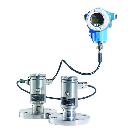
Deltabar FMD71, FMD72
Level measurement with electronic differential
pressure
Electronic differential pressure transmitter with
ceramic and metal sensors
These Instructions are Brief Operating Instructions; they are
not a substitute for the Operating Instructions pertaining to
the device.
Detailed information about the device can be found in the
Operating Instructions and the other documentation.
Available for all device versions via
• Internet:
www.endress.com/deviceviewer
• Smart phone/tablet: Endress+Hauser Operations App
Solutions
Services
Advertisement
Table of Contents

Related Manuals for Endress+Hauser Deltabar FMD71


Summary of Contents for Endress+Hauser Deltabar FMD71
- Page 1 Operating Instructions pertaining to the device. Detailed information about the device can be found in the Operating Instructions and the other documentation. Available for all device versions via • Internet: www.endress.com/deviceviewer • Smart phone/tablet: Endress+Hauser Operations App...
-
Page 2: Serial Number
Deltabar FMD71, FMD72 Order code 00X00-XXXX0XX0XXX Ser. No.: X000X000000 TAG No.: XXX000 Serial number www.endress.com/deviceviewer Endress+Hauser Operations App A0023555 Endress+Hauser... -
Page 3: Table Of Contents
Operation using Endress+Hauser operating program ........ -
Page 4: Document Information
Document information Deltabar FMD71, FMD72 Commissioning ..............36 Post-installation check and function check . - Page 5 Deltabar FMD71, FMD72 Document information 1.2.2 Electrical symbols Symbol Meaning Symbol Meaning Direct current Alternating current Direct current and alternating current Ground connection A grounded terminal which, as far as the operator is concerned, is grounded via a grounding system.
-
Page 6: Documentation
A-A, B-B, C-C, ... Sections Documentation The document types listed are available: In the Download area of the Endress+Hauser website: www.endress.com → Download 1.3.1 Technical Information (TI): planning aid for your device TI01033P: The document contains all the technical data on the device and provides an overview of the accessories and other products that can be ordered for the device. -
Page 7: Terms And Abbreviations
Deltabar FMD71, FMD72 Document information 1.3.4 Safety Instructions (XA) Safety Instructions (XA) are supplied with the device depending on the approval. These instructions are an integral part of the Operating Instructions. Device Directive Documentation Option FMD71, FMD72 ATEX II 1/2G Ex ia IIC T6 Ga/Gb... - Page 8 Document information Deltabar FMD71, FMD72 Term/abbreviation Explanation Document type "Special Documentation" Nominal pressure The MWP (maximum working pressure) for the individual sensors depends on the lowest-rated element, with regard to pressure, of the selected components, i.e. the process connection must be taken into consideration in addition to the measuring cell.
-
Page 9: Registered Trademarks
Deltabar FMD71, FMD72 Basic safety instructions Registered trademarks 1.5.1 HARTâ Registered trademark of the HART Communication Foundation, Austin, USA Basic safety instructions Requirements concerning the staff The staff must fulfill the following requirements for their tasks: ‣ Trained staff: Must have a qualification which corresponds to their function and tasks. -
Page 10: Workplace Safety
Basic safety instructions Deltabar FMD71, FMD72 Verification for borderline cases: ‣ For special fluids and fluids for cleaning, Endress+Hauser is glad to provide assistance in verifying the corrosion resistance of fluid-wetted materials, but does not accept any warranty or liability. 2.2.3... -
Page 11: Product Safety
It meets general safety standards and legal requirements. It also complies with the EC directives listed in the device-specific EC Declaration of Conformity. Endress+Hauser confirms this by affixing the CE mark to the device. Product description Product design See Operating Instructions. -
Page 12: Incoming Acceptance And Product Identification
Incoming acceptance and product identification Deltabar FMD71, FMD72 The FMD71/FMD72 is best suited to level measurement in vessels with pressure overlay or in vacuum vessels and tanks, high distillation columns and other vessels with changing ambient temperatures. The sensor module HP is mounted on the lower measuring connection and the sensor module LP is mounted above the maximum level. - Page 13 Deltabar FMD71, FMD72 Incoming acceptance and product identification A0016052 A0015502 A0016053 Are the goods undamaged? Deltabar DELIVERY NOTE Order code: Ser. no.: Ext. order code: A0015502 Order Code: Ser.-No.: Span Span Mat. Sensor module Deltabar Dat.: Ser. no.: Mat.: A0016054...
-
Page 14: Product Identification
Is the documentation available? If required (see nameplate): Are the safety instructions (XA) present? If one of these conditions is not fulfilled, please contact your Endress+Hauser sales office. Product identification The following options are available for identification of the measuring device: •... - Page 15 Deltabar FMD71, FMD72 Incoming acceptance and product identification Additional nameplate for devices with Ex approval A0021222 Approval-specific information Document number of Safety Instructions or drawing number Additional nameplate for devices with PVDF process connection A0022683 Application limits Endress+Hauser...
- Page 16 Incoming acceptance and product identification Deltabar FMD71, FMD72 4.3.2 Nameplates of the T17 transmitter housing Order code: Ext. ord. cd.: Ser. no.: A0021552 Device name Manufacturer' s address Order number (shortened for re-ordering) Extended order number (complete) Serial number (for clear identification)
-
Page 17: Storage And Transport
Deltabar FMD71, FMD72 Incoming acceptance and product identification Storage and transport 4.4.1 Storage conditions Use original packaging. Store the measuring device in clean and dry conditions and protect from damage caused by shocks (EN 837-2). Storage temperature range –40 to +80 °C (–40 to +176 °F) 4.4.2... -
Page 18: Installation
Installation Deltabar FMD71, FMD72 Installation • No moisture may enter the housing when installing or operating the device, or when establishing the electrical connection. • When measuring in media containing solids, such as dirty liquids, installing separators and drain valves is useful for capturing and removing sediment. -
Page 19: Installing The Sensor Modules
Deltabar FMD71, FMD72 Installation Installing the sensor modules 5.6.1 General installation instructions • The nameplate on the sensor module specifies where the sensor module is typically installed: HP (bottom) LP (top) For further information, see the "Function" section . • Due to the orientation of the sensor modules, there may be a shift in the zero point, i.e. -
Page 20: Mounting Sensor Modules With Pvdf Installation Coupling
Installation Deltabar FMD71, FMD72 Mounting sensor modules with PVDF installation coupling WARNING Risk of damage to process connection! Risk of injury! ‣ Sensor modules with PVDF process connections with threaded connection must be installed with the mounting bracket provided! WARNING... -
Page 21: Seal For Flange Mounting
Deltabar FMD71, FMD72 Installation 5.9.1 Closing the covers on the hygienic stainless steel housing (T17) The covers for the terminal compartment and electronics compartment are hooked into the housing and closed with a screw in each case. These screws must be tightened finger-tight (2 Nm (1.48 lbf ft)) to the stop to ensure that the covers are securely seated and leak-tight. -
Page 22: Electrical Connection
Electrical connection Deltabar FMD71, FMD72 Electrical connection WARNING If the operating voltage is > 35 VDC: Dangerous contact voltage at terminals. Risk of electric shock! ‣ In a wet environment, do not open the cover if voltage is present. The sensor modules have a designation independent of the master/slave configuration. -
Page 23: Connecting The Sensor Module Hp To The Transmitter
Deltabar FMD71, FMD72 Electrical connection 2 3 4 NPT ½" A0017528 BK (black) BU (blue) WH (white) BN (brown) Sensor module LP Sensor module HP Ground terminal Torque 0.4 Nm 6.1.1 Screening with cable shield Screening with cable shield is described in the associated documentation SD00354P. The documentation is provided with the connecting cables. - Page 24 Electrical connection Deltabar FMD71, FMD72 • Screw on the housing cover of the terminal compartment of the sensor module HP. • Guide the cable of the transmitter through the cable gland of the sensor module HP. Use the shielded 4-wire cable that is provided. The wire ends are color-coded to match the corresponding terminal.
-
Page 25: Connecting The Measuring Unit
Deltabar FMD71, FMD72 Electrical connection Connecting the measuring unit 6.3.1 Terminal assignment WARNING Supply voltage might be connected! Risk of electric shock and/or explosion! ‣ Switch off the supply voltage before connecting the device. WARNING Electrical safety is compromised by an incorrect connection! ‣... - Page 26 Electrical connection Deltabar FMD71, FMD72 Test Test Test 4... 20mA 4... 20mA Test A0019989 Housing Supply voltage 4 to 20 mA Devices with integrated overvoltage protection are labeled "OVP" (overvoltage protection) here. External ground terminal 4 to 20 mA test signal between positive and test terminal Internal ground terminal, minimum supply voltage = 12 V DC, jumper is set as illustrated in the diagram.
-
Page 27: Connection Conditions
Deltabar FMD71, FMD72 Electrical connection Connection conditions 6.4.1 Cable specification Preferably use twisted, screened two-wire cable. 6.4.2 Cable specification for transmitter connection See Operating Instructions. 6.4.3 Cable entries See Operating Instructions. 6.4.4 Overvoltage protection Standard version The standard version of the pressure instruments does not contain any special elements to protect against overvoltage ("wire to ground"). -
Page 28: Operation Options
Operation options Deltabar FMD71, FMD72 Operation options Operation without an operating menu 7.1.1 Position of operating elements Operating keys on the exterior of the device With the T14 housing (aluminum or stainless steel), the operating keys are located either outside of the housing, under the protection cap or inside on the electronic insert. In addition, devices with an onsite display and a 4 to 20 mA HART electronic insert have operating keys on the onsite display. - Page 29 Deltabar FMD71, FMD72 Operation options Operating keys and elements located internally on the electronic insert 1 2 3 Display HART FIELD COMMUNICATION PROTOCOL Sensor A0016500 DIP switch for locking/unlocking parameters relevant to the measured value DIP switch for switching damping on/off DIP switch for alarm current SW/Alarm min (3.6 mA)
-
Page 30: Operation With An Operating Menu
Operation options Deltabar FMD71, FMD72 Function of the operating elements Operating key(s) Meaning Press for at least 3 Adopt lower range value. A reference seconds pressure is present at the device. For a detailed description, see also "Pressure A0017535 measuring mode" section (see "Operating Instructions"), or "Level measuring mode"... -
Page 31: Structure Of The Operating Menu
Deltabar FMD71, FMD72 Operation options Structure of the operating menu User role Submenu Meaning/use Operator Language Only consists of the "Language" parameter (000) where the operating language for the device is specified. The language can always be changed even if the device is locked. -
Page 32: Operating Options
Operation options Deltabar FMD71, FMD72 Operating options 7.4.1 Local operation A0017650 Display and operating module with push buttons. Cover must be opened for operation. Operating the device using onsite display (optional) A 4-line liquid crystal display (LCD) is used for display and operation. The onsite display shows measured values, dialog text as well as fault and notice messages in plain text, thereby supporting the user in every stage of operation. - Page 33 Deltabar FMD71, FMD72 Operation options 7.5.1 Overview – A0016498 Operating keys Bargraph Symbol Header Parameter ID number 7.5.2 Setting the contrast on the display module • and (press simultaneously): increases the contrast. • and (press simultaneously): decreases the contrast.
- Page 34 Operation options Deltabar FMD71, FMD72 7.5.4 Navigation and selection from list The operating keys are used to navigate through the operating menu and to select an option from a picklist. Operating key(s) Meaning • Navigate downwards in the picklist • Edit the numerical values and characters within a function A0017879 •...
-
Page 35: Operation Using Endress+Hauser Operating Program
"Pos. zero adjust" parameter. 4 Cancel Use to exit edit mode for the parameter. Confirm User-definable parameters See Operating Instructions. Operation using Endress+Hauser operating program See Operating Instructions. Direct access to parameters See Operating Instructions. Locking/unlocking operation See Operating Instructions. -
Page 36: Commissioning
Commissioning Deltabar FMD71, FMD72 Commissioning NOTICE If a pressure smaller than the minimum permitted pressure or greater than the maximum permitted pressure is present at the device, the following messages are output in succession: ‣ "S140 Working range P LP/HP" or "F140 Working range P LP/HP" (depending on the setting in the "Alarm behav. - Page 37 Deltabar FMD71, FMD72 Commissioning • Position adjustment (zero point correction) • Setting the lower and upper pressure value and assigning to the lower or upper level value • Device reset, see "Function of the operating elements" section, table → 35.
-
Page 38: Commissioning With An Operating Menu
Commissioning Deltabar FMD71, FMD72 Set the lower pressure value. Does the LED on the electronic insert light up briefly? Applied pressure was saved as the lower pressure value Applied pressure was not saved as the lower pressure ("Empty pressure") and assigned to the lower level value value. -
Page 39: Measuring Mode Selection
Deltabar FMD71, FMD72 Commissioning Options • English • Another language (as selected when ordering the device) • Possibly a third language (language of the manufacturing plant) Factory setting English 9.5.2 Configuring language via operating tool (FieldCare) See Operating Instructions. Measuring mode selection... -
Page 40: Selecting The Pressure Engineering Unit
Commissioning Deltabar FMD71, FMD72 Write permission Operators/Service engineers/Expert Description Define which sensor module corresponds to the high- pressure side. Options • Sensor module HP • Sensor module LP Factory setting Sensor module HP Selecting the pressure engineering unit Press. eng. unit (125) Navigation Setup →... - Page 41 Deltabar FMD71, FMD72 Commissioning Write permission Operators/Service engineers/Expert Description Displays the measured pressure after the differential pressure buildup and position adjustment. Note If this value is not equal to "0", it can be corrected to "0" by the position adjustment.
-
Page 42: Configuring Level Measurement
Commissioning Deltabar FMD71, FMD72 9.10 Configuring level measurement 9.10.1 Information on level measurement You have a choice of two methods for calculating the level: "In pressure" and "In height". The table in the "Overview of level measurement" section that follows provides you with an overview of these two measuring tasks. - Page 43 Deltabar FMD71, FMD72 Commissioning 9.10.4 "In pressure" level selection Calibration without reference pressure (dry calibration) Example: In this example, the volume in a tank should be measured in liters. The maximum volume of 1 000 l (264 gal) corresponds to a pressure of 450 mbar (6.53 psi).
- Page 44 Commissioning Deltabar FMD71, FMD72 Description Select the "Dry" option via the "Calibration mode (027)" parameter. Menu path: Setup → Extended setup → Level → Calibration mode Enter the volume value for the lower calibration point via the "Empty calib. (028)"...
-
Page 45: Linearization
Deltabar FMD71, FMD72 Commissioning Description If the process uses a medium other than that on which the calibration was based, the new density must be specified in the "Process Density" parameter. Menu path: Setup → Extended setup → Current output → Process density. - Page 48 *71281267* 71281267 www.addresses.endress.com...