Table of Contents
Advertisement
Quick Links
Download this manual
See also:
User Manual
Advertisement
Table of Contents

Related Manuals for Fluke 1529


Summary of Contents for Fluke 1529
- Page 1 1529 Chub-E4 Thermometer Readout Technical Guide Revision 930501-EN...
- Page 2 Limited Warranty & Limitation of Liability Each product from Fluke Corporation, Hart Scientific Division ("Hart") is warranted to be free from defects in material and workmanship under normal use and service. The warranty period is 2 years for the Thermometer Readout. The warranty period begins on the date of the shipment. Parts, product repairs, and services are warranted for 90 days.
-
Page 3: Table Of Contents
Users Guide Table of Contents Introduction and Safety Information ........1 Symbols Used ................... 1 Safety Information ..................3 1.2.1 Warnings ....................3 1.2.2 Cautions ....................4 Authorized Service Centers ..............4 Specifications and Environmental Conditions ......7 Specifications ................... 7 Environmental Conditions ................. 8 Quick Start ................9 Unpacking .................... - Page 4 1529 Chub-E4 Thermometer Readout Display Backlight and Contrast .............. 21 Taking Measurements ................21 5.8.1 Connecting the Sensor ..................21 5.8.2 Enabling the Channel ..................21 5.8.3 Selecting Conversion Type and Probe Characterization ......21 Fast Measurement Mode ................ 22 5.10 Data Logging ..................22 Menu Functions ..............23...
- Page 5 Users Guide Digital Communications Interface ........67 Overview ....................67 Communications ..................67 7.2.1 Serial Wiring ....................67 7.2.2 GPIB Communications ..................68 Interface Commands ................69 7.3.1 Command Summary ..................69 7.3.2 Command Syntax ..................74 Commands ..................... 75 7.4.1 Measurement Commands ................76 7.4.2 Measurement Control Commands ..............79 7.4.3 Channel Commands ..................82...
- Page 6 1529 Chub-E4 Thermometer Readout 10.1 Troubleshooting ..................125 10.1.1 Self-Test Error Messages ................126 10.1.2 Start-up Error Messages ................127 10.2 Downloading Auto Logged Data ............127 10.3 CE Comments ..................128 10.3.1 EMC Directive .....................128 10.3.2 Low Voltage Directive (Safety) ..............129 10.4 Frequently Asked Questions ..............
- Page 7 Users Guide Figures Figure 1 Using the Clamp-on Ferrites ............. 10 Figure 2 Front Panel ..................13 Figure 3 Back Panel ..................14 Figure 4 Probe Connection Wiring Diagram ........... 19 Figure 5 Thermocouple Connections ............. 20 Figure 6 Main Menu ..................23 Figure 7 Channel Menu ...................
- Page 8 1529 Chub-E4 Thermometer Readout Figure 36 Auto Log View Data ................. 55 Figure 37 Print Data ..................56 Figure 38 Delete Data ..................56 Figure 39 Log Stats ..................57 Figure 40 Data Labels ..................58 Figure 41 Default Labels .................. 59 Figure 42 System Menu ...................
- Page 9 Table 1 Symbols used ..................2 Table 2 Conversion Types ................31 Table 3 Matching Certificate Values to the 1529 ITS-90 Coefficients ....32 Table 4 Setting Coefficients Rtpw, a8, b8, a4, and b4 ........33 Table 5 Field Types ..................42 Table 6 REF Display Keywords ................
-
Page 11: Introduction And Safety Information
Symbols Used 1 Introduction and Safety Information The Hart 1529 is a low-cost, high-accuracy, digital thermometer readout designed to be used with 25 and 100 W PRTs, thermistors, and thermocouples. Its unique combi- nation of features makes it suitable for a wide variety of applications from laboratory measurement to industrial processes. -
Page 12: Table 1 Symbols Used
1529 Chub-E4 Thermometer Readout Symbols Used Table 1 Symbols used Symbol Description AC (Alternating Current) AC-DC Battery Complies with European Union directives Double Insulated Electric Shock Fuse PE Ground Hot Surface (Burn Hazard) Read the User’s Guide (Important Information) Canadian Standards Association... -
Page 13: Safety Information
Introduction and Safety Information Safety Information Symbol Description The European Waste Electrical and Electronic Equipment (WEEE) Directive (2002/96/ EC) mark. 1.2 Safety Information Use this instrument only as specified in this manual. Otherwise, the protection provided by the instrument may be impaired. Refer to the safety information in The following sections. -
Page 14: Cautions
1529 Chub-E4 Thermometer Readout Authorized Service Centers supply, and have it replaced. Do not attempt to open, repair, or continue using a damaged or defective AC adapter. The instrument batteries can present danger if not handled properly. To avoid ●... - Page 15 Introduction and Safety Information Authorized Service Centers Fluke Corporation, Hart Scientific Division 799 E. Utah Valley Drive American Fork, UT 84003-9775 Phone: +1.801.763.1600 Telefax: +1.801.763.1010 E-mail: support@hartscientific.com Fluke Nederland B.V. Customer Support Services Science Park Eindhoven 5108 5692 EC Son...
- Page 16 1529 Chub-E4 Thermometer Readout Authorized Service Centers Fluke South East Asia Pte Ltd. Fluke ASEAN Regional Office Service Center 60 Alexandra Terrace #03-16 The Comtech (Lobby D) 118502 SINGAPORE Phone: +65 6799-5588 Telefax: +65 6799-5588 E-mail: antng@singa.fluke.com When contacting these Service Centers for support, please have the following infor-...
-
Page 17: Specifications And Environmental Conditions
Specifications and Environmental Conditions Specifications 2 Specifications and Environmental Conditions 2.1 Specifications Thermistor Thermocouple 2 channels PRT/thermistor and 2 channels thermocouple Inputs or 4 channels PRT/thermistor or 4 channels thermocouple PRT/thermistor channels accept 2,3, or 4 wires Thermocouple channels accept B, E, J, K, N, R, S, T, and Au-Pt thermocouple types –189 to 960 °C –50 to 150 °C... -
Page 18: Environmental Conditions
1529 Chub-E4 Thermometer Readout Environmental Conditions Thermistor Thermocouple Probe Connection Patented DWF connectors accepts spade lug, Universal receptacle accepts bare-wire, or banana plug terminations miniature and standard connectors Communications RS-232 port included, IEEE-488 (GPIB) optional AC Power 100 to 240 VAC, 50-60 Hz, 0.4A DC Power 12 to 16 VDC, 0.5 A (battery charges during operation from 14.5 to 16 VDC, 1.0A) -
Page 19: Quick Start
Authorized Service Centers on page 4) 3.2 Use Proper Care You must understand the safety issues related to the 1529. Be aware that potential haz- ards exist due to high temperatures and battery chemicals. Carefully read the Warnings and Cautions in Section 1.2, Safety Information on page 3. -
Page 20: Connect The Power Source
DC input or the internal re-chargeable battery pack. To use the AC adapter, plug it into a wall outlet of the appropriate voltage and insert the DC plug into the DC power input of the 1529 (see Figure 3 on page 14). 3.6 Switch the Power On Power is turned on and off with the power switch located on the top right corner of the back panel. - Page 21 Quick Start Measure Temperature aged if misused. For further suggestions on handling the probe and using the 1529 and probe to measure temperature accurately, see Section 5, General Operation on page 17. For information on the various modes of operation of the 1529 see Section 6, Menu...
-
Page 23: Parts And Controls
RS-232 port connector, IEEE-488 port connector (optional), serial label, and probe connectors. The 1529 thermometer readout can be configured in three different ways. The configuration affects the probe connectors on the back panel. The Model 1529 is configured with one PRT/thermistor input module of two channels and one thermo-... -
Page 24: Figure 3 Back Panel
1529 Chub-E4 Thermometer Readout Back Panel couple input module of two channels. The Model 1529-R is configured with two PRT/ thermistor input modules of four channels. The Model 1529-T is configured with two thermocouple input modules of four channels. Figure 3 shows the back panel and the three different configurations. -
Page 25: Accessories
(PRT/thermistor probes) or to the universal receptacle (thermocouples) for operation. 4.3 Accessories The 1529 thermometer readout comes standard with a hand strap on the side for easy carrying of the instrument. The following accessories are also available: 2513-1529 Rack Mount Kit ●... -
Page 27: General Operation
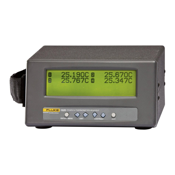
1529 remotely. 5.1 Display The 1529 display consists of two parts. The top portion of the display is used for displaying the measurements from one to four inputs. The bottom portion of the dis- play is reserved for the programmable fields and field display sets. Information about the channels and measurements can be displayed in greater detail such as min, max, spread, standard deviation, and many other functions. -
Page 28: Probe Input Modules
The battery pack can be easily removed and replaced in the field by following this procedure: 1. Power the 1529 off and unplug the AC adapter from the unit. 2. Turn the 1529 over to expose the battery compartment. Remove the battery cover hex screw. -
Page 29: Figure 4 Probe Connection Wiring Diagram
General Operation Probe Input Modules When using 2- and 3-wire sensors, the accuracy of the 1529 is reduced as stated in the specifications. Compensation is made for 3-wire PRTs, but the difference in lead resistance affects the measurement accuracy. The 1529 thermometer readout is unable to compensate for 2-wire lead resistance. -
Page 30: Connecting A Thermocouple
The DC power source provides power to charge the battery. It can also be used to pow- er the 1529 while the battery is being charged. The AC adapter provided with the 1529 is intended for these purposes. The DC power source plugs into the DC power input on the back panel of the instrument. -
Page 31: Power On Self-Test
Taking Measurements 5.6 Power On Self-Test When power is turned on, the 1529 performs a self-test checking the system, all chan- nels, calibration, GPIB, memory, and buttons. If an error occurs, an error message is displayed. See Section 10.1, Troubleshooting on page 125 for additional information on error messages. -
Page 32: Fast Measurement Mode
1529 Chub-E4 Thermometer Readout Fast Measurement Mode The conversion type and characterization coefficients for a sensor are specified using the PROBE menu EDIT PROBE function (see Section 6.2.1, Edit Probe on page 30). 5.9 Fast Measurement Mode Fast Measurement Mode applies to measure periods of 0.1, 0.2, or 0.5 seconds. This mode allows measurements to be displayed or logged quickly. -
Page 33: Menu Functions
6 Menu Functions Selecting the Enter/Menu button from the front panel accesses the main menu of the 1529 thermometer readout. The main menu consists of the submenus: CHANNEL, PROBE, FIELDS, LOGGING, and SYSTEM. Each submenu has its own set of functions. -
Page 34: Measure Period And Fast Measurement Mode
1529 Chub-E4 Thermometer Readout Channel Menu 24.159C 24.634C 24.142C 24.015C MEASUREMENT CONTROL FUNCTIONS MEASURE ENABLE CHANNEL MOVING DISPLAY PERIOD CHANNEL MODE AVERAGE OPTIONS 1529 CHUB E-4 THERMOMETER READOUT ENTER / MENU UNIT CONTRAST EXIT Figure 7 Channel Menu 6.1.1 Measure Period and Fast Measurement Mode The MEASURE PERIOD function allows you to control the period (time) between measurements. - Page 35 When the measure period is set to less than 1 second (i.e. 0.1, 0.2, 0.5 seconds) the 1529 enters the Fast Measurement Mode. The menu buttons may seem to be sluggish in this mode as the processor is making faster measurements. When in the Fast Mea- surement Mode, the following changes occur at 0.1, 0.2, and 0.5 seconds.
-
Page 36: Enable Channel
AUTO-CAL function. To reduce the uncertainty in the Fast Measure- ment Mode, use the 1529 in a controlled ambient environment, in a very stable bath or dry block at lower temperatures, and use the AUTO-CAL function often. -
Page 37: Moving Average
Menu Functions Channel Menu 24.159C 24.634C 24.142C 24.015C SC MODE: SIMULT 1529 CHUB E-4 THERMOMETER READOUT ENTER / MENU UNIT CONTRAST EXIT Figure 10 Channel Mode The following scan modes are available: SCAN - measures enabled channels scanning through and displaying the ●... -
Page 38: Display Options/Auto-Cal
1529 Chub-E4 Thermometer Readout Channel Menu 24.159C 24.634C 24.142C 24.015C AVERAGE: 1529 CHUB E-4 THERMOMETER READOUT ENTER / MENU UNIT CONTRAST EXIT Figure 11 Moving Average The measurements are averaged together until the selected number of measurements to average has been reached. Then the calculated average is based on the selected number of measurements to average. -
Page 39: Probe Menu
Menu Functions Probe Menu 24.159C 24.634C 24.142C 24.015C RESOL: DECIMAL: LAMP: 1529 CHUB E-4 THERMOMETER READOUT ENTER / MENU UNIT CONTRAST EXIT Figure 12 Display Options The RESOL parameter determines the number of decimal places (0 through 4 or AUTO) to be displayed for the temperature measurements. If AUTO is selected, the instrument automatically determines the number of decimal places to display depend- ing on the probe conversion type. -
Page 40: Edit Probe
1529 Chub-E4 Thermometer Readout Probe Menu 24.159C 24.634C 24.142C 24.015C PROBE CHARACTERIZATION FUNCTIONS EDIT COPY TEST PRINT DEFAULT PROBE PROBE PROBE PROBE PROBE 1529 CHUB E-4 THERMOMETER READOUT ENTER / MENU UNIT CONTRAST EXIT Figure 13 Probe Menu 6.2.1 Edit Probe... -
Page 41: Table 2 Conversion Types
Menu Functions Probe Menu protected, the bottom portion of the display shows the probe channel, the probe serial number and the conversion type. The characterization coefficients and parameters are displayed after the conversion type is selected. The PROBE parameter is for selecting any one of the four input channels: CHAN1, CHAN2, CHAN3 and CHAN4 or one of the ten probe memory channels: PMEM0, PMEM1, PMEM2, PMEM3, PMEM4, PMEM5, PMEM6, PMEM7, PMEM8, and PMEM9. -
Page 42: Table 3 Matching Certificate Values To The 1529 Its-90 Coefficients
The following example demonstrates how to set the ITS-90 parameters for the case where a PRT was calibrated to ITS-90 and its calibration certificate states values for coefficients Rtpw, a4, b4, a8, and b8. Set the 1529 parameters with values from the certificate as follows. -
Page 43: Table 4 Setting Coefficients Rtpw, A8, B8, A4, And B4
Menu Functions Probe Menu Table 4 Setting Coefficients Rtpw, a8, b8, a4, and b4 Setting Coefficients Rtpw, a8, b8, a4, and b4 1529 ITS-90 Coefficients Certificate Value RTPW Rtpw 6.2.1.2 ITS-SR5 The ITS-SR5 conversion is a special case of the ITS-90 conversion type. This conver- sion is for the ITS-90 sub-range 5 only. - Page 44 1529 Chub-E4 Thermometer Readout Probe Menu α − δ − ≥ 100 100 °C ...
- Page 45 Menu Functions Probe Menu The WIRES parameter sets the appropriate number of lead wires from the sensor. This parameter can be set to 2-, 3-, or 4-wires. See Figure on page for the wiring configuration. 6.2.1.6 Thermistor T(R) Conversion [THERM-T] The following Steinhart-Hart equation is used for the thermistor T(R) conversion: ( ) [ ] −...
- Page 46 1529 Chub-E4 Thermometer Readout Probe Menu and hold the Exit button to cancel to the main display or press the EXIT button to cancel and to move to the next parameter. On the last parameter, press the Exit button to exit to the menu.
-
Page 47: Copy Probe
Menu Functions Probe Menu 6.2.1.11 Thermocouple Polynomial Conversion Note: An Application Note for use of Tungsten-Rhenium and other thermocou- ples is available at www.hartscientific.com. The thermocouple polynomial conversion allows calculation of temperature by poly- nomial conversion. When the Thermocouple Polynomial conversion type is selected, the coefficients are displayed on the right portion of the bottom of the display. -
Page 48: Test Probe
1529 Chub-E4 Thermometer Readout Probe Menu 24.159C 24.634C 24.142C 24.015C FROM CH: PMEMO TO CH: CHAN1 SERIAL: TYPE: PT100 1529 CHUB E-4 THERMOMETER READOUT ENTER / MENU UNIT CONTRAST EXIT Figure 15 Copy Probe Use the LR buttons to select the source channel or memory location. Press the Enter button to save the new setting. -
Page 49: Print Probe
24.159C 24.634C 24.142C 24.015C PROBE: PROBE: CHAN1 PORT: SERIAL 1529 CHUB E-4 THERMOMETER READOUT ENTER / MENU UNIT CONTRAST EXIT Figure 17 Print Probe Use the LR buttons to select the channel, memory location, or ALL. Use the UD buttons to scroll between parameters. Press the Enter button to continue and to send the data to the selected port. -
Page 50: Fields Menu
1529 Chub-E4 Thermometer Readout Fields Menu 24.159C 24.634C 24.142C 24.015C PROBE: CHAN1 1529 CHUB E-4 THERMOMETER READOUT ENTER / MENU UNIT CONTRAST EXIT Figure 18 Default Probe Use the LR buttons to select the channel, memory location, or ALL. Press the Enter button to reset the probe coefficients. -
Page 51: Clear Stats
When this function is selected, the bottom portion of the display states that you must press the Enter button to clear the statistical data. 24.159C 24.634C 24.142C 24.015C CLEAR STATISTICAL DATA. Press ENTER to continue... 1529 CHUB E-4 THERMOMETER READOUT ENTER / MENU UNIT CONTRAST EXIT Figure 20 Clear Stats Press the Enter button to clear the statistical data. -
Page 52: Figure 21 Select Fields
1529 Chub-E4 Thermometer Readout Fields Menu 24.159C 24.634C 24.142C 24.015C [1]* [5]* DISPLAY: [2]* [6]* [3]* [7]* [4]* [8]* ALOG TIME 1529 CHUB E-4 THERMOMETER READOUT ENTER / MENU UNIT CONTRAST EXIT Figure 21 Select Fields Use the LR buttons to select the display set number. Press the Enter button to save the new setting and exit. -
Page 53: Edit Fields
DISPLAY: [2]* [6]* [3]* [7]* [4]* [8]* ALOG TIME 1529 CHUB E-4 THERMOMETER READOUT ENTER / MENU UNIT CONTRAST EXIT Figure 22 Edit Fields The rightmost portion of the bottom of the display shows the current settings for the eight fields for the selected display set. The field numbers appear in the square brack-... -
Page 54: Default Fields
1529 Chub-E4 Thermometer Readout Fields Menu is editable and indicates the channel (‘*’, or 1 through 4). If the ‘*’ is selected and you are in simultaneous mode, channel one is displayed. If you are in scan mode, select- ing the ‘*’ displays the current channel. The field item is editable and is to the right of the channel. -
Page 55: Logging Menu
Menu Functions Logging Menu 24.159C 24.634C 24.142C 24.015C RESOL: DECIMAL: LAMP: 1529 CHUB E-4 THERMOMETER READOUT ENTER / MENU UNIT CONTRAST EXIT Figure 24 Display Options The RESOL parameter determines the number of decimal places (0 through 4 or AUTO) to be displayed for the temperature measurements. If AUTO is selected, the instrument automatically determines the number of decimal places to display depend- ing on the conversion type. -
Page 56: Demand Log
1529 Chub-E4 Thermometer Readout Logging Menu 24.159C 24.634C 24.142C 24.015C DATA RECORDING FUNCTIONS DEMAND AUTO DATA DEFAULT STATS LABELS LABELS 1529 CHUB E-4 THERMOMETER READOUT ENTER / MENU UNIT CONTRAST EXIT Figure 25 Logging Menu 6.4.1 Demand Log The DEMAND LOG submenu (Figure 26 on this page) allows measurements to be logged on demand, one reading at a time. -
Page 57: Figure 27 Store Readings
When the instrument is in simultaneous mode, all channels that are displayed on the upper portion of the 1529 display are stored simultaneously to the demand log. When the instrument is in scan mode, the channel currently displayed on the upper portion of the 1529 display is the only measurement that is stored to the demand log. -
Page 58: Figure 28 Log History
1529 Chub-E4 Thermometer Readout Logging Menu When this function is selected, the bottom portion of the display shows the demand log history data. 24.159C 24.634C 24.142C 24.015C DATA_01 11:39:04 10-12-00 DATA_01 11:39:04 10-12-00 DATA_01 11:39:04 10-12-00 DATA_01 11:39:04 10-12-00 1529... -
Page 59: Figure 29 Demand Log View Data
29.629 C 11:39:04 DATA_01 24.086 C 11:39:04 DATA_01 24.048 C 11:39:04 1529 CHUB E-4 THERMOMETER READOUT ENTER / MENU UNIT CONTRAST EXIT Figure 29 Demand Log View Data Press the UD buttons to scroll up and down through the stored readings sequentially. -
Page 60: Figure 30 Print Data
1529 Chub-E4 Thermometer Readout Logging Menu 24.159C 24.634C 24.142C 24.015C LABEL: ALL DATA PORT: SERIAL 1529 CHUB E-4 THERMOMETER READOUT ENTER / MENU UNIT CONTRAST EXIT Figure 30 Print Data Use the LR buttons to select the parameter settings. Use the UD buttons to scroll between parameters. -
Page 61: Auto Log
Menu Functions Logging Menu 24.159C 24.634C 24.142C 24.015C DELETE: ALL DATA 1529 CHUB E-4 THERMOMETER READOUT ENTER / MENU UNIT CONTRAST EXIT Figure 31 Delete Data Use the LR buttons to select the label of the data you want to delete. Press the En- ter button to continue and delete the data. -
Page 62: Figure 33 Logging Options
1 hour. The LOG PER must be set to a value less than or equal to the measurement pe- riod. The 1529 will not log readings faster than the measurement period. The measure- ment period is set in the MEASURE PERIOD function of the CHANNEL menu and is the rate at which readings are taken. -
Page 63: Figure 34 Start Stop
START RECORDING DATA. If an auto log session is run- ning, the user is prompted to STOP RECORDING DATA. 24.159C 24.634C 24.142C 24.015C START RECORDING DATA. Press ENTER to continue... 1529 CHUB E-4 THERMOMETER READOUT EXIT ENTER / MENU UNIT CONTRAST Figure 34 Start Stop Note: The log is not started or stopped until the Enter button is pressed to con- firm the user action. -
Page 64: Figure 35 Log Statistics (Auto Log Started)
1529 Chub-E4 Thermometer Readout Logging Menu After a log session is started, the bottom portion of the display shows the log statistics. These statistics can also be viewed from the LOG STATS function of the LOGGING menu. 24.159C 24.634C 24.142C 24.015C... -
Page 65: Figure 36 Auto Log View Data
24.147 C 12:23:24 0003: 29.637 C 12:23:24 0004: 23.972 C 12:23:24 1529 CHUB E-4 THERMOMETER READOUT ENTER / MENU UNIT CONTRAST EXIT Figure 36 Auto Log View Data Each time the view data function is accessed the current auto log memory is displayed. -
Page 66: Figure 37 Print Data
1529 Chub-E4 Thermometer Readout Logging Menu 24.159C 24.634C 24.142C 24.015C LABEL: ALL DATA PORT: SERIAL 1529 CHUB E-4 THERMOMETER READOUT ENTER / MENU UNIT CONTRAST EXIT Figure 37 Print Data Use the LR buttons to select the parameter settings. Use the UD buttons to scroll between parameters. -
Page 67: Log Stats
FILLED: 4.0% FILLED: 18.5% FREE: 95, 4 FREE: 6654, 1506 1529 CHUB E-4 THERMOMETER READOUT ENTER / MENU UNIT CONTRAST EXIT Figure 39 Log Stats The left side displays demand log statistics and the right side displays the auto log statistics. -
Page 68: Default Labels
1529 Chub-E4 Thermometer Readout Logging Menu 24.159C 24.634C 24.142C 24.015C SELECT: DATA_01 1529 CHUB E-4 THERMOMETER READOUT ENTER / MENU UNIT CONTRAST EXIT Figure 40 Data Labels Press the LR buttons to select the label to edit. By default the labels are set to DATA_01, DATA_02, …... -
Page 69: System Menu
The functions that appear in this menu are COMM SETUP, DATE TIME, PASSWORD, CALIBRA- TION, and SYSTEM RESET. 24.159C 24.634C 24.142C 24.015C 1529 HART 0.50 SERNUM COMM DATE CALI- SYSTEM PASS- SETUP... -
Page 70: Comm Setup
The 1529 thermometer readout is shipped standard with one serial (RS-232) port. A GPIB port may optionally be installed. The GPIB port selection only appears if it is installed. -
Page 71: Date Time
Menu Functions System Menu The PRINT parameter allows the user to enable printing measurements over the serial port. Selecting ON enables printing and selecting OFF disables printing. With slower MEA PER (see Section ) and SER PER rates of 1 second or more, measurements are printed with the channel number, measured value, unit, time, and date, all separated with spaces. -
Page 72: Password
1529 Chub-E4 Thermometer Readout System Menu 24.159C 24.634C 24.142C 24.015C HOUR: DAY: MINUTE: MONTH: SECOND: YEAR: 2000 D FORM: M-D-YY T FORM: 24 HR 1529 CHUB E-4 THERMOMETER READOUT ENTER / MENU UNIT CONTRAST EXIT Figure 44 Date Timie The HOUR parameter allows the user to set the current hour (0 through 23). -
Page 73: Figure 45 Password
EXIT Figure 45 Password By default the password is set to ‘1529’ when the instrument ships from the factory. We recommend that the user change the default password to protect the password- protected settings. Note: Keep your password in a secure location and do not forget it. -
Page 74: Calibration
Calibration The CALIBRATION function is used for accessing parameters and functions related to the 1529 calibration. It first displays the date the current calibration is due and the date the instrument should be recalibrated. Typically, all channels should have the same due date. -
Page 75: System Reset
(See .Figure 45 on page 63) By default the password is set to ‘1529’ when the instrument ships from the factory. We recommend that the user change the default password to protect the password- protected settings. -
Page 76: Figure 47 System Reset
1529 Chub-E4 Thermometer Readout System Menu If an incorrect password is entered the display shows the message PASSWORD INCORRECT and access to the password-protected parameters is denied. Press the Enter button to return to the menu. If the correct password is entered, the bottom por- tion of the display instructs the user to press Enter to reset the settings to the defaults. -
Page 77: Digital Communications Interface
7.1 Overview The communication feature allows an external device, such as a computer, to com- municate with the 1529 to obtain measurement data and control operating conditions. Communication is accomplished by issuing commands to the 1529 through RS-232 or IEEE-488 communication ports. -
Page 78: Gpib Communications
The serial period, baud rate, linefeed, and echo are programmable. Refer to Section , Serial Port, for instructions on accessing and setting these parameters. All commands sent to the 1529 through the serial interface must be terminated with a carriage return or linefeed character. -
Page 79: Interface Commands
7.2.2.2 Connection The IEEE-488 port is located on the back of the 1529. Use a standard IEEE-488 cable to connect to your GPIB controller. A shielded cable should be used to prevent EM emission. 7.2.2.3 Device Setup The Model 1529 system must be set up to respond to the controller address. - Page 80 1529 Chub-E4 Thermometer Readout Interface Commands Command Description Refer To CALCulate:AVERage<n>:TYPE? Returns the keyword for the specified calculation type Section 7.4.1.3 number CALCulate<chn>:CONVert:CATalog? Returns a list of conversion types available for the Section 7.4.4.1 specified channel CALCulate<chn>:CONVert:COPY<dest chn>|ALL Copies the conversion type, sub-ranges (ITS-90), serial Section 7.4.4.2...
- Page 81 Digital Communications Interface Interface Commands Command Description Refer To CALibrate<chn>:PARameter:SCALe<n>? Returns the calibration scale parameter for the specified Section 7.4.5.8 [MIN|MAX|DEF] channel CALibrate<chn>:PARameter:SCALe<n> Sets the calibration scale parameter for the specified Section 7.4.5.9 <num>|MIN|MAX|DEF channel DISPlay:DATE:FORMat? [MIN|MAX|DEF] Returns a number indicating the date format Section 7.4.10.1 DISPlay:DATE:FORMat <num>...
- Page 82 1529 Chub-E4 Thermometer Readout Interface Commands Command Description Refer To LOGging:AUTomatic:VALue? <num> Returns an auto log reading Section 7.4.7.13 |MIN|MAX|DEF LOGging:DEMand:DELete [<num>|ALL] Deletes demand log entries Section 7.4.7.14 LOGging:DEMand:FREE? Returns the number of log entries free and stored Section 7.4.7.15...
- Page 83 Digital Communications Interface Interface Commands Command Description Refer To STATus:OPERation:ENABle? [MIN|MAX|DEF] Returns the Operation Status Enable Register Section 7.4.12.15 STATus:OPERation:ENABle <num> |MIN|MAX|DEF Sets the Operation Status Enable Register Section 7.4.12.16 STATus:QUEStionable? Reads and clears the Questionable Status Register Section 7.4.12.17 STATus:QUEStionable:CONDition? Returns the Questionable Status Condition Register Section 7.4.12.18...
-
Page 84: Command Syntax
The 1529 accepts commands that set parameters, execute functions or respond with requested data. These commands are in the form of strings of ASCII-encoded charac- ters. As far as possible, the 1529 conforms to IEEE-488.2, 1992 and SCPI-1994. One notable exception is that compound commands are not allowed as explained below. -
Page 85: Commands
Digital Communications Interface Commands 7.4 Commands Table 7 on page 69, Alphabetical List of Commands, lists the commands in alphabeti- cal order. In this section the commands are arranged into the following groups: Measurement Commands – commands for reading measurement data. Measurement Control Commands –... -
Page 86: Measurement Commands
1529 Chub-E4 Thermometer Readout Commands For query commands, specifying the MIN, MAX, or DEF parameter causes ● the instrument to respond with the minimum, maximum, or default setting respectively. For set commands, specifying the MIN, MAX, or DEF parameters causes the ●... - Page 87 Digital Communications Interface Commands 7.4.1.2 CALCulate<chn>:AVERage<n>:DATA? Returns the value of a statistical calculation for a given channel. CALC3:AVER1:DATA? 0.017 The CALCulate suffix, <chn>, specifies the channel (1 to 4). The AVERage suffix, <n>, specifies the calculation type. See Table on page for the Statistical Calculation Types.
- Page 88 1529 Chub-E4 Thermometer Readout Commands scale, hour, minute, seconds, year, month, day the measurement was made With this format kohms and millivolts are not converted to ohms and volts. This command may return the same reading if a new reading has not yet been ob- tained.
-
Page 89: Measurement Control Commands
Digital Communications Interface Commands 0.0113 This command is the same as the ?FETCh [<chn>] command. 7.4.1.9 SENSe<chn>:DATA? Returns the input value for the specified channel. SENS3:DATA? 100.0291, 0.0000 The SENSe suffix, <chn>, specifies the channel (1 to 4). The parameter is ohms for low range PRTs, Kohms for high range PRTs and thermistors, and millivolts for ther- mocouples. - Page 90 1529 Chub-E4 Thermometer Readout Commands 7.4.2.4 SENSe:AVERage:COUNt <num>|MIN|MAX|DEF Sets the moving average filter setting. SENS:AVER:COUN MIN The <num> parameter must be a number between 1 and 10. Specifying the MIN, MAX, or DEF parameter sets the moving average filter setting to the minimum, maxi- mum, or default, respectively.
- Page 91 Digital Communications Interface Commands This command only applies to PRT/Thermistor channels. Executing this command on Thermocouple channels generates a -294, “Incompatible type”, error message. The SENSE suffix, <chn>, specifies the channel (1 to 4), or memory channel (5 to 14). Specifying the MIN parameter returns a value of 2.
-
Page 92: Channel Commands
1529 Chub-E4 Thermometer Readout Commands Specifying the MIN, MAX, or DEF parameter sets the scan sequence timer to the minimum, maximum, or default value respectively. The *RST command sets the scan sequence timer to 1 second. 7.4.3 Channel Commands The channel commands are used for querying and setting the current channel, the channels to scan, the type of scanning, and the state of the channel scanning. -
Page 93: Probe Commands
Digital Communications Interface Commands 8.4.3.5 7.4.3.5 ROUTe:SCAN? Returns a comma delimited list of the enabled channels. ROUT:SCAN? (@2,3,4) The list of channels is enclosed in parenthesis and preceded with the @ symbol. 7.4.3.6 ROUTe:SCAN <chn list> Sets the channels for scanning. ROUT:SCAN 2,3 The <chn list>... - Page 94 1529 Chub-E4 Thermometer Readout Commands conversion for a channel. The probe commands for copying and setting parameters are password protected. 7.4.4.1 CALCulate<chn>:CONVert:CATalog? Returns a list of conversion types available for the specified channel. CALC2:CONV:CAT? “RES”,“ITS”,”ITS5”,”PT”,”CVD”,”TRES”,”TTEM”,”YSI” The CALCulate suffix, <chn>, specifies the channel (1 to 4) or memory channel (5 to 14).
- Page 95 Digital Communications Interface Commands 7.4.4.4 CALCulate<chn>:CONVert:NAMe <conv> Sets the conversion type for the specified channel. CALC2:CONV:NAME CVD The CALCulate suffix, <chn>, specifies the channel (1 to 4) or memory channel (5 to 14). The <conv> parameter is a mnemonic indicating the conversion type. The ac- ceptable conversion types depend on the channel type.
- Page 96 1529 Chub-E4 Thermometer Readout Commands quotes, followed by its value (i.e. “param1”,value1,”param2”,value2,”param3”,valu e3,...). 7.4.4.7 CALCulate<chn>:CONVert:PARameter:VALue <param>,<num>[,< param>,<num>...] Sets the value of one or more conversion parameters for the specified channel. CALC2:CONV:PAR:VAL RTPW, 100.0145, A4, 0.0045 The CALCulate suffix, <chn>, specifies the channel (1 to 4) or memory channel (5 to 14).
-
Page 97: Calibration Coefficient Commands
Digital Communications Interface Commands 7.4.4.10 CALCulate<chn>:CONVert:SNUMber <serl> Sets the probe serial number for the specified channel. CALC2:CONV:SNUM A_336C The CALCulate suffix, <chn>, specifies the channel (1 to 4) or memory channel (5 to 14). The <serl> parameter is in string format. The <serl> parameter can consist of up to eight characters that include any letters, numeric digits, and the underscore ‘_’. - Page 98 1529 Chub-E4 Thermometer Readout Commands 2000,9,22 The CALibrate suffix, <chn>, specifies the channel (1 to 4). This command does not apply to memory channels. The response is returned in the format, <year>,<month>,<day>. Specifying the MIN parameter returns a value of 2000,1,1.
- Page 99 Digital Communications Interface Commands This command is password-protected. To access this command, the password must be successfully entered using the SYST:PASS:CEN <pass> command (see Section 9.4.11, Password Commands). 7.4.5.6 CALibrate<chn>:PARameter:OFFSet<n>? [MIN|MAX|DEF] Returns the calibration offset parameter for the specified channel. CAL1:PAR:OFFS2? –1.2 The CALibrate suffix, <chn>, specifies the channel (1 to 4).
- Page 100 1529 Chub-E4 Thermometer Readout Commands The CALibrate suffix, <chn>, specifies the channel (1 to 4). This command does not apply to memory channels. For PRT/Thermistor channels, the calibration scale suffix <n> specifies the resistance range parameter for PRTs (1) or Thermistors (2). For Ther- mocouple channels, the calibration scale suffix <n>...
- Page 101 Digital Communications Interface Commands Specifying the MIN parameter returns a value of -9 when the linearity suffix <n> is 1 (for PRTs) and -9000 when the linearity suffix <n> is 2 (for Thermistors). Specifying the MAX parameter returns a value of 9 when the linearity suffix <n> is 1 (for PRTs) and 9000 when the linearity suffix <n>...
-
Page 102: Display Commands
1529 Chub-E4 Thermometer Readout Commands The RJC suffix, <chn>, specifies the channel (1 to 4). This command does not apply to memory channels. The <num> parameter specifies the RJC value for the specified channel. Specifying the MIN, MAX, or DEF parameter sets the RJC parameter to the minimum, maximum, or default value respectively. - Page 103 Digital Communications Interface Commands DISP:LAMP ON The lamp can be turned on or off by using either the <bool> parameter (ON or OFF), the <num> parameter (0, 1, 2 or 3), or the MIN, MAX or DEF parameters. Specifying the <bool> parameter to ON turns on the lamp. Specifying the MIN, MAX, or DEF sets the lamp to the minimum, maximum, or default value respectively.
-
Page 104: Logging Commands
1529 Chub-E4 Thermometer Readout Commands 7.4.6.9 DISPlay:WINDow<n>:FIELd<n>:FEED? Returns the current setting of the specified field for the specified display set. DISP:WIND1:FIEL2:FEED? 0,16 The WINDow suffix, <n>, specifies the display set (1 to 9). The FIELd suffix, <n>, specifies the field (1 to 8) within the display set. The response consists of two num- bers separated by a comma. - Page 105 Digital Communications Interface Commands 7.4.7.3 LOGging:AUTomatic:COUNt <num>|MIN|MAX|DEF Sets the number of measurements to be stored to the auto log during an auto log session. LOG:AUT:COUN 100 The <num> parameter is the number of measurements to be stored in the auto log dur- ing the auto log session.
- Page 106 1529 Chub-E4 Thermometer Readout Commands LOG:AUT:POIN? Specifying the MAX parameter returns the total number of entries that can be stored in the auto log. 7.4.7.8 LOGging:AUTomatic:PRINt [<num>|ALL [,<port>]] Prints the auto log entries. LOG:AUT:PRIN ALL DATA_25 1 22.676C 12:19:42 09-05-00 DATA_25 2 9.960 KO 12:19:44 09-05-00...
- Page 107 Digital Communications Interface Commands 7.4.7.11 LOGging:AUTomatic:TIMe? [MIN|MAX|DEF] Returns the auto log interval setting. LOG:AUT:TIM? Specifying the MIN parameter returns a value of 0.1. Specifying the MAX parameter value returns value of 3600. Specifying the DEF parameter returns a value of 1. The units are seconds.
- Page 108 1529 Chub-E4 Thermometer Readout Commands 7.4.7.15 LOGging:DEMand:FREE? Returns the number of demand log entries free and stored. LOG:DEM:FREE? 87,12 The response consists of two numbers separated by a comma. The first number indi- cates the number of demand log entries still available. The second number indicates the number of entries already stored.
- Page 109 Digital Communications Interface Commands LOG:DEM:PRIN 23,1 DATA_23 1 22.862C 14:59:43 09-05-00 DATA_23 2 9.963 KO 14:59:44 09-05-00 DATA_23 3 23.097C 14:59:45 09-05-00 DATA_23 4 23.202C 14:59:46 09-05-00 If no parameters are specified, the ALL parameter is assumed and all demand log entries are printed to the serial port.
-
Page 110: System Commands
Returns a list of input modules installed. *OPT? PRT,TC Input module types are reported by position, top to bottom, of the two input modules. The returned example is for a 1529 equipped with one 2-channel PRT input module and one 2-channel Thermocouple input module. 7.4.8.3 *RST Sets the instrument operating parameters to defined conditions. - Page 111 Digital Communications Interface Commands 7.4.8.4 SYSTem:BOOT:VERSion? Returns the boot ROM version. SYST:BOOT:VERS? 0.50 7.4.8.5 SYSTem:CODE:VERSion? Returns the firmware code version. SYST:CODE:VERS? 1.11 7.4.8.6 SYSTem:ERRor? Returns a system error message if any are present in the system error queue. SYST:ERR? 0,“No error” Each error condition produces only one error message at a time.
-
Page 112: Communication Interface Commands
1529 Chub-E4 Thermometer Readout Commands 7.4.8.9 UNIT:TEMPerature? Returns the system temperature units. UNIT:TEMP? The response is either C for Celsius, F for Fahrenheit, or K for Kelvin. 7.4.8.10 UNIT:TEMPerature <unit> Sets the system temperature units. UNIT:TEMP C The <unit> parameter is either C or CEL for Celsius, F or FAR for Fahrenheit, or K or Kelvin for Kelvin. - Page 113 Digital Communications Interface Commands SYST:COMM:SER:FDUP? A value of 1 is returned if serial port echo (duplex) is ON. A value of 0 is returned if serial port echo (duplex) is OFF. Specifying the MIN parameter returns a value of 0. Specifying the MAX parameter returns a value of 1.
- Page 114 1529 Chub-E4 Thermometer Readout Commands A value of 1 is returned if linefeed is enabled. A value of 0 is returned if linefeed is disabled. Specifying the MIN parameter returns a value of 0. Specifying the MAX parameter returns a value of 1. Specifying the DEF parameter returns a value of 1.
-
Page 115: Date And Time Commands
Digital Communications Interface Commands 7.4.9.12 SYSTem:KLOCkout <bool>|MIN|MAX|DEF Sets the state of the keypad lockout. SYST:KLOC 1 The <bool> parameter turns the keypad lockout on (1 or ON) or off (0 or OFF). Speci- fying the MIN, MAX, or DEF parameter sets the keypad lockout to the minimum, maximum, or default respectively. - Page 116 1529 Chub-E4 Thermometer Readout Commands 7.4.10.2 DISPlay:DATE:FORMat <num>|MIN|MAX|DEF Sets the date format setting. DISP:DATE:FORM 1 The <num> parameter specifies the number of the desired date format. See Table on page , Date Formats, for a list of acceptable time formats. Specifying the MIN, MAX, or DEF parameter sets the date format to the minimum, maximum, or default respectively.
-
Page 117: Password Commands
Digital Communications Interface Commands The <year>, <month>, and <day> parameters must all be supplied. The <year> param- eter is a four-digit number (2000 to 2099). The <month> parameter is a one or two- digit number (1 to 12). The <day> parameter is a one or two-digit number (1 to 31). Specifying the MIN, MAX or DEF parameter sets the system date to the minimum, maximum, or default value respectively. - Page 118 1529 Chub-E4 Thermometer Readout Commands SYST:PASS:CEN 1234 The <pass> parameter is the current system password. This command must be sent to allow the user to access password-protected settings. After sending this command, use the SYST:PASS:CEN:STAT? command to verify success. 7.4.11.3 SYSTem:PASSword:CENable:STATe? Returns the current password protection state.
-
Page 119: Status Commands
Digital Communications Interface Commands SYST:PASS:NEW 1212 The <pass> parameter must be a 4-digit number (0000 to 9999). The password is re- quired to access the indicated settings. This command is password protected. To access this command, the password must be successfully entered using the SYST:PASS:CEN <pass>... - Page 120 1529 Chub-E4 Thermometer Readout Commands 7.4.12.6 *SRE <num>|MIN|MAX|DEF Sets the Service Request Enable Register. *SRE 32 7.4.12.7 *STB? Returns the Status Byte Register. *STB? 7.4.12.8 *TST? Performs a self-test and reports any errors that are found. *TST? 7.4.12.9 STATus:MEASure? Reads and clears the Measurement Status Register.
- Page 121 Digital Communications Interface Commands bit 1: channel 2 measurement in process bit 2: channel 3 measurement in process bit 3: channel 4 measurement in process bits 4-15: not used 7.4.12.11 STATus:MEASure:ENABle? Returns the Measurement Status Enable Register. STAT:MEAS:ENAB? 7.4.12.12 STATus:MEASure:ENABle <num> Sets the Measurement Status Enable Register.
- Page 122 1529 Chub-E4 Thermometer Readout Commands 7.4.12.15 STATus:OPERation:ENABle?[MIN|MAX|DEF] Returns the Operation Status Enable Register. STAT:OPER:ENAB? 7.4.12.16 STATus:OPERation:ENABle <num>|MIN|MAX|DEF Sets the Operation Status Enable Register. STAT:OPER:ENAB 16 7.4.12.17 STATus:QUEStionable? Reads and clears the Questionable Status Register. STAT:QUES? The assignment of the bits in this register is as follows:...
-
Page 123: Statistical Calculation Types
Digital Communications Interface Commands 7.4.12.20 STATus:QUEStionable:ENABle <num>|MIN|MAX|DEF Sets the Questionable Status Enable Register. STAT:QUES:ENAB 10 7.4.13 Statistical Calculation Types The statistical calculation types are listed in the following table. Table 8 Statistical Calculation Types Number Type Keyword Average Standard Deviation Minimum Maximum Spread... -
Page 124: Conversion Types And Parameters
1529 Chub-E4 Thermometer Readout Commands Number Keyword Field Type Maximum Spread Statistical n (Number of Measurements Comprising Statistics) ALOG Logging Indicator BATT Battery Percent Remaining MEAS Number of Seconds Until Next Measurement Note: When the field type reference (REF) is selected, the displayed keyword changes depending on the probe type. -
Page 125: Port Numbers
Digital Communications Interface Commands Probe Type Conversion Type Mnemonic Port Response Thermocouple TC-K (default) TC-K MilliVolts VIN[mV] TC-B TC-B TC-E TC-E TC-J TC-J TC-N TC-N TC-R TC-R TC-S TC-S TC-T TC-T TC-AU/PT TC-AU/PT AuPT Polynomial TC-POLY POLY Table 12 Conversion Types and Parameters Conversion Type Parameters Range, Wires, RTPW, A4, B4, A, B, C, D... -
Page 126: Date And Time Formats
1529 Chub-E4 Thermometer Readout Commands 7.4.17 Date and Time Formats The following tables list the acceptable date and time formats and their number setting. Table 15 Date Formats Number Format MM-DD-YY MM-DD-YYYY DD/MM/YY DD/MM/YYYY Table 16 Time Formats Number Format... -
Page 127: Calibration
PRT and Thermistor Calibration 8 Calibration Each channel of the 1529 is calibrated independently of the other channels and has its own set of calibration parameters. The 1529 should be calibrated at regular intervals to ensure that it continues to measure with proper accuracy. Calibration should only be done by qualified, authorized personnel. -
Page 128: Figure 49 Using A Shorting Wire
1529 Chub-E4 Thermometer Readout PRT and Thermistor Calibration rameter must be done last as the adjustments of C0 and C100 affect the measurement at 400 W but C400 does not affect the measurements at 0 W or 100 W. Each channel must be calibrated. -
Page 129: Thermistor Calibration Parameters
Calibration PRT and Thermistor Calibration 8.1.3 Thermistor Calibration Parameters Three adjustable parameters are used for calibration: C0K, C10K, and C100K. The C0K directly affects the measurement at 0 W. It has negligible effect at 10 kW but significant affect at higher resistances. The C10K directly affects the measurement at 10 kW. -
Page 130: Thermocouple Calibration
–0.0006 mV, adjust the C0 parameter by adding 0.0006. If it was previously 0.0000 it should now be 0.0006. 2. Set the voltage source to 100 mV and measure the voltage with the 1529 and the voltmeter simultaneously. Adjust the C100 parameter by subtracting the measured error. - Page 131 4. Connect the calibrated thermocouple to the thermocouple channel and insert the thermocouple into the temperature source. Measure the temperature with the 1529 (be sure to program the channel with the correct thermocouple type). Adjust the CRJ parameter by subtracting the measured error. For example, if the thermocouple temperature is actually 0.0 °C but the 1529 reads 0.184 °C,...
-
Page 133: Maintenance
Maintenance Maintenance The calibration instrument has been designed with the utmost care. Ease of ● operation and simplicity of maintenance have been a central theme in the product development. Therefore, with proper care the instrument should require very little maintenance. Avoid operating the instrument in oily, wet, dirty, or dusty environments. -
Page 135: Troubleshooting
Thermocouple Conversions on page 36). You can use the TEST PROBE function to test the temperature conversion calculation. The measurement is out of range. The 1529 may not be able to calculate temperature accurately if the resistance or voltage is outside the valid range. The measured resistance or voltage may be too low or too high if the actual temperature is too low or too high or if there is a problem with the sensor. -
Page 136: Self-Test Error Messages
After the power is switched on allow the 1529 at least one minute to complete its self-test and power on sequence. Then, try to adjust the contrast using the contrast buttons. -
Page 137: Start-Up Error Messages
The following steps should be followed to download logged data using the serial port: 1. Connect the 1529 to a COM port on the computer using the serial cable. 2. Run a terminal program such as Windows® Terminal or HyperTerminal®. -
Page 138: Ce Comments
“LOG:DEM:PRIN” to initiate the download process. c. The 1529 should immediately begin downloading the data. If no readings have been stored, the 1529 will not respond to these commands. For more details on using these commands, see Section 7.4.7.8, LOGging:AUTomatic:PRINt [<num>|ALL [,<port>]] on page 96 and Section 7.4.7.19, LOGging:DEMand:PRINt [<num>|ALL [,<port>]] on page... -
Page 139: Low Voltage Directive (Safety)
10.4 Frequently Asked Questions 10.4.1 Battery 1. What type of batteries does the Model 1529 use? The Model 1529 uses a built- in Nickel-Metal-Hydride battery pack. 2. How long do I need to charge the battery initially? The batteries come fully charged. -
Page 140: Input
Yes, the Model 1529 charges while in use without affecting the charging time or its performance. 15. If I am using the Model 1529 with AC power and a power outage occurs, will the batteries automatically take over? Yes, when AC power is removed from the Model 1529 for any reason, the batteries automatically supply back up power without risk of losing any data. -
Page 141: Logging
10.4.4 Output 1. How do I get data from the Model 1529 to my PC? Data can be transferred to your PC via an RS-232 interface. 2. Can the Model 1529 be set to simultaneous measurement mode and log to the serial port? Yes. - Page 143 Index date 42, 61 DATE TIME 61 DC power 20 decimal 29, 45 Symbols DEFAULT FIELDS 44 DEFAULT LABELS 58 2-wire probe 32, 33 DEFAULT PROBE 39 3-wire probe 32, 33 4-wire probe 32, 33 DELETE DATA 50, 56 delta temperature 42 DEMAND LOG 46 AC adapter 17, 20 difference temperature 42...
- Page 144 1529 Chub-E4 Thermometer Readout range;resistance 32, 33, 34 reference junction 36, 43 lamp 29, 45 reset 65 linefeed 60 resistance 34, 42, 43 log count 53 resolution 29, 45 logging 22, 52, 127 RJC 36 LOGGING menu 45 RS-232 60, 67...
- Page 145 YSI-400 36...