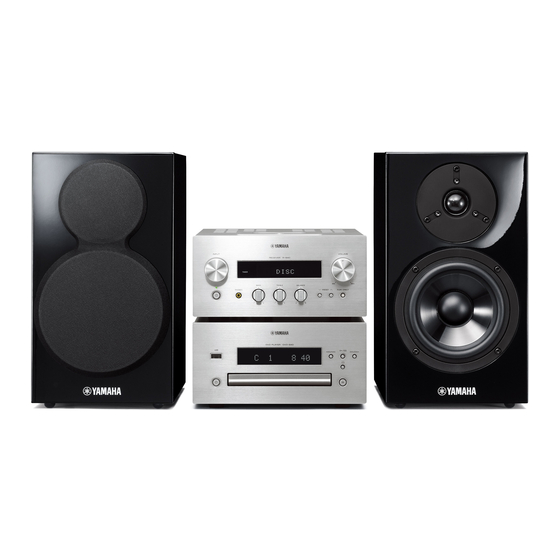
Yamaha NS-BP300 Service Manual
Micro component system receiver/speaker package
Hide thumbs
Also See for NS-BP300:
- Owner's manual (444 pages) ,
- Owner's manual (92 pages) ,
- Owner's manual (60 pages)
Table of Contents
Advertisement
MICRO COMPONENT SYSTEM
R-840/
• When accepting a repair order from the user, it is recommended to receive the R-840 and BD-940/DVD-840/CD-
640 as a set for the repair work.
• The MCR-940 consists of the R-840, BD-940 and NS-BP300.
The MCR-840 consists of the R-840, DVD-840 and NS-BP300.
The MCR-640 consists of the R-840, CD-640 and NS-BP300.
This service manual is for the R-840/NS-BP300. For service manual of the BD-940/DVD-840/CD-640, please refer
to the following publication numbers:
BD-940: 1011 5 4
This manual has been provided for the use of authorized YAMAHA Retailers and their service personnel.
It has been assumed that basic service procedures inherent to the industry, and more specifi cally YAMAHA Products, are already known
and understood by the users, and have therefore not been restated.
WARNING:
IMPORTANT:
The data provided is believed to be accurate and applicable to the unit(s) indicated on the cover. The research, engineering, and service
departments of YAMAHA are continually striving to improve YAMAHA products. Modifications are, therefore, inevitable and
specifi cations are subject to change without notice or obligation to retrofi t. Should any discrepancy appear to exist, please contact the
distributor's Service Division.
WARNING:
IMPORTANT:
■ CONTENTS
To Service Personnel ............................................2
System Composition ................................................3
Front Panels .........................................................4–6
Rear Panels ......................................................... 7–11
Remote Control Panels ..................................... 12
Specifications ................................................... 13–15
Internal View .......................................................... 16
Disassembly Procedures ............................. 17–19
Updating Firmware ..........................................20–24
Self-Diagnostic Function ............................25–37
1 0 1 1 5 3
MCR-940/MCR-840/MCR-640
RECEIVER/
SERVICE MANUAL
/ DVD-840: 1011 5 5
IMPORTANT NOTICE
Failure to follow appropriate service and safety procedures when servicing this product may result in personal injury,
destruction of expensive components, and failure of the product to perform as specifi ed. For these reasons, we advise
all YAMAHA product owners that any service required should be performed by an authorized YAMAHA Retailer or
the appointed service representative.
The presentation or sale of this manual to any individual or fi rm does not constitute authorization, certifi cation or
recognition of any applicable technical capabilities, or establish a principle-agent relationship of any form.
Static discharges can destroy expensive components. Discharge any static electricity your body may have
accumulated by grounding yourself to the ground buss in the unit (heavy gauge black wires connect to this buss).
Turn the unit OFF during disassembly and part replacement. Recheck all work before you apply power to the unit.
Display Data .............................................................40
Ic Data ...................................................................41–44
Pin Connection Diagrams .............................45–47
Block Diagram ........................................................49
Printed Circuit Boards .................................50–62
Schematic Diagrams .......................................63–70
Replacement Parts List ................................71–79
REMOTE CONTROL .....................................................80
System Connector ..........................................81–82
Copyright © 2009
This manual is copyrighted by YAMAHA and may not be copied or
redistributed either in print or electronically without permission.
SPEAKER PACKAGE
NS-BP300
/ CD-640: 1011 5 6
All rights reserved.
P.O.Box 1, Hamamatsu, Japan
'09.11
Advertisement
Table of Contents

Related Manuals for Yamaha NS-BP300


Summary of Contents for Yamaha NS-BP300
- Page 1 This manual has been provided for the use of authorized YAMAHA Retailers and their service personnel. It has been assumed that basic service procedures inherent to the industry, and more specifi cally YAMAHA Products, are already known and understood by the users, and have therefore not been restated.
-
Page 2: To Service Personnel
R-840/NS-BP300 ■ TO SERVICE PERSONNEL AC LEAKAGE 1. Critical Components Information WALL EQUIPMENT TESTER OR OUTLET UNDER TEST EQUIVALENT Components having special characteristics are marked must be replaced with parts having specifications equal to those originally installed. 2. Leakage Current Measurement (For 120V Models Only) -
Page 3: System Composition
The MCR-840 consists of the R-840, DVD-840 and NS-BP300. The MCR-640 consists of the R-840, CD-640 and NS-BP300. This service manual is for the R-840/NS-BP300. For service manual of the BD-940/DVD-840/CD-640, please refer to the following publication numbers: BD-940: 1011 5 4... -
Page 4: Front Panels
R-840/NS-BP300 ■ FRONT PANELS R-840 Top view C, T, K, A, B, G, L, V models A, B models Front view C, T, K, A, L, V models... - Page 5 R-840/NS-BP300 B, G models...
- Page 6 R-840/NS-BP300 NS-BP300 C, T, K, A, B, G, L, V models...
-
Page 7: Rear Panels
R-840/NS-BP300 ■ REAR PANELS R-840 C model T model... - Page 8 R-840/NS-BP300 K model A model...
- Page 9 R-840/NS-BP300 B model G model...
- Page 10 R-840/NS-BP300 L model V model...
- Page 11 R-840/NS-BP300 NS-BP300 C, T, K, A, B, G, L, V models C, K, A, B, G, L, V models T model...
-
Page 12: Remote Control Panels
R-840/NS-BP300 ■ REMOTE CONTROL PANELS MCR-940 MCR-840 MCR-640 B, G, F models C, T, K, A, L, V models G, F models C, L, V models B, G models Key colors A. Red B. Green C. Yellow D. Blue... -
Page 13: Specifications
R-840/NS-BP300 ■ SPECIFICATIONS R-840 ■ Audio Section ■ DAB Section [A, B models] Minimum RMS Output Power (Power Amp. Section) Tuning Range (L/R drive, 1 kHz, 10 % THD, 6 ohms) ............174.0 to 240 MHz (BAND III) C, T, K, A, B, G, V models ..........65 W + 65 W L model .................60 W + 60 W... - Page 14 R-840/NS-BP300 is a trademark. NS-BP300 ■ Speaker Section Type ......... 2-way bass reflex speaker system Driver “BD-LIVE” logo is a trademark of Blu-ray Disc Association. Woofer ..........13 cm (5-1/8") cone type Tweeter ..........2.5 cm (1") soft dome type Frequency Response ......55 Hz to 28 kHz (-10dB) “BONUSVIEW”...
- Page 15 R-840/NS-BP300 • DIMENSIONS R-840 Top view Front view 177 (7") 215 (8-1/2") Unit: mm (inch) NS-BP300 305 (12") Front view Side view 280 (11") (7/8") (1/8") (3/4") (3/4") (1") (1") Unit: mm (inch) (6-7/8")
-
Page 16: Internal View
R-840/NS-BP300 ■ INTERNAL VIEW R-840 Top view Top view Front view MAIN (8) P.C.B. MAIN (2) P.C.B. DAB P.C.B. (A, B models) DAB MODULE (A, B models) FM TUNER FUNCTION (1) P.C.B. MAIN (5) P.C.B. MAIN (1) P.C.B. POWER TRANSFORMER MAIN (7) P.C.B. -
Page 17: Disassembly Procedures
R-840/NS-BP300 ■ DISASSEMBLY PROCEDURES (Remove parts in disassembly order as numbered.) Disconnect the power cable from the AC outlet. 1. Removal of Top Cover Unit 2. Removal of Front Panel Unit Remove 4 screws ( ① ) and 4 screws ( ② ). (Fig. 1) Remove 2 screws ( ③... - Page 18 R-840/NS-BP300 3. Removal of Amp Unit Remove 2 screws ( ⑥ ), 2 screws ( ⑦ ), 3 screws ( ⑧ ), 3 screws ( ⑨ ) and screw ( ⑩ ). (Fig. 2) b. Remove CB103, CB403 and CB505. (Fig. 2) Remove the amp unit together with the MAIN (1) P.C.B., the FUNCTION (1) P.C.B.
- Page 19 R-840/NS-BP300 When checking the P.C.B.s: • Spread the rubber sheet and the cloth. Then place the amp unit on the cloth and check it. (Fig. 3) • Connect the ground point of the rear panel to the chassis with a ground lead or the like. (Fig. 3) •...
-
Page 20: Updating Firmware
R-840/NS-BP300 ■ UPDATING FIRMWARE When the following parts are replaced, the firmware must be updated to the latest version. MAIN P.C.B. Microprocessor (IC101) of FUNCTION P.C.B. ● Required tools ● Preparation and precautions • Firmware downloader program • Download the firmware downloader program and ............ - Page 21 R-840/NS-BP300 ● Connection Disconnect the power cable of this unit from the AC outlet. 1. Set the switch (SW301) of RS232C conversion adaptor to the “FLASH UCOM” position. (Fig. 1) 2. Connect the writing port (CB104 of FUNCTION P.C.B.) located on the rear panel of this unit to the serial port (RS232C) of the PC with RS232C cross cable, RS232C conversion adaptor and flexible flat cable as shown below.
- Page 22 R-840/NS-BP300 ● Operation procedure 1. Connect the power cable of this unit to the AC outlet. The power to this unit is supplied and the microprocessor is in the writing mode. 2. Start up FlashSta.exe. The screen appears as shown below. (Fig. 2) 3.
- Page 23 R-840/NS-BP300 5. Click [Setting], and set the baud rate. (Fig. 4) Select 115200 bps for the baud rate and 40 ms for the program intervals. Reduce the baud rate if a transmission error occurs frequently. Fig. 4 6. Click [E.P.R.], then the “Erase” screen appears. (Fig. 5) 7.
- Page 24 R-840/NS-BP300 8. When writing of the firmware is completed, the screen appears as shown below. (Fig. 6) Click [OK]. (Fig. 6) 9. Click [Exit] to end FlashSta.exe. (Fig. 6) Fig. 6 10. Disconnect the power cable of this unit from the AC outlet.
-
Page 25: Self-Diagnostic Function
R-840/NS-BP300 ■ SELF-DIAGNOSTIC FUNCTION There are 10 main menu items, each of which has sub-menu items. Listed in the table below are main menu items and sub-menu items. MAIN MENU SUB-MENU 1 VER/DEST/SUM 1 FIRMWARE VERSION / DESTINATION 2 CHECKSUM... - Page 26 R-840/NS-BP300 ● Starting Self-Diagnostic Function Turn the “BALANCE” knob counterclockwise fully and then while pressing the “PURE DIRECT” key of this unit as shown in the figure below, press the “ ” (On/Standby) key to turn on the power. The self-diagnostic function mode is activated.
- Page 27 R-840/NS-BP300 ● Display provided when Self-Diagnostic Function started The FL display of this unit displays the history of protection function data then the main menu (sub-menu FIRMWARE VERSION/DESTINATION of main menu No. 1 VER/DEST/SUM) a few seconds later. When there is no history of protection function:...
- Page 28 R-840/NS-BP300 ● Operation procedure of Main menu and Sub-menu There are 10 main menu items, each of them having sub-menu items. Main menu and Sub-menu selection Both main menu and sub-menu can be selected by using the “INPUT” knob. Parameter selection The parameter can be selected by using the “PRESET...
- Page 29 R-840/NS-BP300 ● Details of Self-Diagnostic Function menu 1. VER/DEST/SUM This menu is used to display the firmware version, checksum and destination. The checksum is obtained by adding the data at every 8-bit for each program area and expressing the result as a 4-figure hexadecimal data.
- Page 30 R-840/NS-BP300 2. FL DISPLAY CHECK This menu is used to check the FL display section/indicators for displaying/indicating. Using the sub-menu, the display condition changes as shown below. 2-1. Initial display “ ” (On/Standby) indicator: On (Green) 2 1 . D I S P...
- Page 31 R-840/NS-BP300 3. FACTORY PRESET This menu is used to reserve/inhibit initialization of the back-up IC. Select this menu and press the “PRESET ” (Up) key to change display. PRESET INHIBIT (Initialization inhibited) 3 0 . P R T I N H Back-up IC initialization is not executed.
- Page 32 R-840/NS-BP300 4-4. THM Temperature detection Temperature of the heatsink is detected by IC501 of the MAIN P.C.B.. Normal value: 41 to 317 (Reference voltage: 5.0 V = 1023) 4 4 . T H M : 0 1 8 6 If THM becomes out of the normal value range, the protection function works to turn off the power.
- Page 33 R-840/NS-BP300 4-A. KEY Panel keys detection The voltage at 74 pin (I-KEY0) of microprocessor IC101 is displayed. (Reference voltage: 5.0 V = 1023) 4 A . K E Y : 1 0 2 3 Key detection for A/D port Key input (A/D) pull-up resistance 10 k-ohms +1.2 k...
- Page 34 R-840/NS-BP300 5. PROTECTION HISTORY This menu is used to display the history of protection function. 5-0. DSP / RST Select this menu and press the “PRESET ” (Up) key to change display. DSP: Displayed. 5 0 . H I S T D S P RST: Initialization of the history of protection function is reserved.
- Page 35 R-840/NS-BP300 6. EEPROM CHECK This menu is used to check the communicating condition between the microprocessor (IC101) and the EEPROM (IC102) on the FUNCTION P.C.B.. 6 1 . E P R M : O K OK : No error detected...
- Page 36 R-840/NS-BP300 9. POWER OFF FACTOR HISTORY This menu is used to display the history of power off factor. Select this menu and press the “PRESET ” (Up) key to change display. Example 9-1 History 1 9 1 . N O H I S T...
- Page 37 R-840/NS-BP300 A. SYSTEM CONNECTOR This menu is used to check the SYSTEM connector without connecting the BD/DVD/CD player to this unit. With the power to this unit turned off, short between pins No. 1 (SYS_MOSI) and No. 4 (SYS_MISO), between pins No.
- Page 38 R-840/NS-BP300 ■ CONFIRMATION OF IDLING CURRENT OF AMP UNIT 1) No signal applied. 2) Non-loaded condition. 3) Aging is not necessary. Item Test Point Rating (DC) Note MAIN L: R578 CB504 1 – 2 pin If the measured voltage exceeds 2.6 mV, cut the lead wire of R562 (L ch) or 0.05mV –...
- Page 39 R-840/NS-BP300 MAIN (1) P.C.B. Test point MAIN R: 0.05 mV to 2.5 mV (DC) Front side CB504 MAIN L: R578 (L ch) 0.05 mV to 2.5 mV (DC) Q513 R562 (cut off) R579 (R ch) Q514 R563 (cut off) Rear side Notes) •...
- Page 40 R-840/NS-BP300 ■ DISPLAY DATA ● V801 : 12-ST-73GINK (MAIN P.C.B.) ● PIN CONNECTION Pin No. Connection Pin No. Connection TSB TSA RESET OSC VDD PGND LGND Note: 1) F1, F2 ..Filament 2) NP ..No pin 3) NX ..No extended pin 4) DL ..
- Page 41 R-840/NS-BP300 ■ IC DATA IC101: R5F3640DNFA (FUNCTION P.C.B.) Single-chip 16-bit CMOS microprocessor Port P0 Port P1 Port P2 Port P3 Port P4 Port P5 VCC2 ports Internal peripheral functions UART or clock synchronous Clock generation circuit serial I/O Timer (16-bit)
- Page 42 R-840/NS-BP300 Function Name Port Name Detail of Function (P.C.B.) P9_6/ANEX1/SOUT4 RDS_N_RST RDS reset control P9_5/ANEX0/CLK4 RDS_SCK Serial clock for RDS communication P9_4/DA1/TB4IN RDS_RDY RDS READY input terminal P9_3/DA0/TB3IN FL_N_IC FL initial clear control P9_2/TB2IN/SOUT3 FL_SDT FL serial communication data P9_1/TB1IN/SIN3...
- Page 43 R-840/NS-BP300 Function Name Port Name Detail of Function (P.C.B.) ON/OFF control of the +5SPC power supply (L = ON / H = OFF: for reduction of standby power) Fixed at Low usually 42 P5_4/HLDA 5SPC O [O] The standby power is reduced (MCUSleep) by setting at Hi after the...
- Page 44 R-840/NS-BP300 Function Name Port Name Detail of Function (P.C.B.) 82 P0_6/AN0_6/D6 MODEL Model distinction 83 P0_5/AN0_5/D5 MVOL+ Direction control of upside of MOTOR VOLUME 84 P0_4/AN0_4/D4 MVOL- Direction control of downside of MOTOR VOLUME 85 P0_3/AN0_3/D3 86 P0_2/AN0_2/D2 LED_EON EON LED control...
-
Page 45: Pin Connection Diagrams
R-840/NS-BP300 ■ PIN CONNECTION DIAGRAMS • ICs BA15218F KIA7809API-U/P LB1641 LC72725KM-UY-TLM-E LM61CIZ VOUT LME49723MAX/NOPB MFI341S2164 M24C02-RDW6TP NJM2068MD-TE2 NJM2388F05 NJM2388F33 1. VIN 2. VOUT 3. GND 4. ON/OFF CONTROL NJM2752RB0 NJM4580E NJW1194V PQ012GN01ZPH R1154H058B-T1-F 1: Vin 2: VB 3: Vout 4: NC... - Page 46 R-840/NS-BP300 • Diodes 1SR139 1SS133 1SS355 D5SBA60 1SR400 1SS176 Anode Anode Anode – Cathode Cathode Cathode + AC HZU10B2 KBP103G 1.0A 200V MTZJ5.1B RB501V-40 MTZJ5.1C HZU2.7B2 TRF-E MTZJ8.2C HZU3.0B1 TRF-E MTZJ12C HZU3.9B2 TRF-E MTZJ27C HZU4.7B2 TRF-E Anode Anode Anode HZU5.1B2 TRF-E HZU5.6B TRF-E...
- Page 47 R-840/NS-BP300 • Transistors 2SA1037K 2SA1145 2SA1694 O,P,Y 2SA1708 2SA1770S/T-AN 2SB1257 2SC4467 O,P,Y 2SC4488 2SC1740S 2SC1815 Y 2SC2412K 2SC3326-A (TE85R, F) 2SC4614S/T-AN 2SC2229 2SC3326-B (TE85R, F) 2SD2014 2SD2704 K 2SD2705S TP 2SK2158-T2B-A 2SK246-Y (F) 2SK3850 3LN01C-TB-E DTA114EKA HN4C06J KTA1517S DTC144EKA KTC3911S 1.
- Page 48 R-840/NS-BP300 MEMO...
-
Page 49: Block Diagram
R-840/NS-BP300 ■ BLOCK DIAGRAM (G model) Q302 REG. FUNCTION (C, T, K, A, L, V models) J322,323 IC301 –65 → IC303 SCHEMATIC DIAGRAM IC302 IC305 FM TUNER 3,30 1,10 MODULE RY501 (A, B models) IC304 8,25 POWER SPEAKERS IC306 Q507,508 AMP. -
Page 50: Printed Circuit Boards
R-840/NS-BP300 ■ PRINTED CIRCUIT BOARDS POINT D 1 / CB103 (+5BU), 2 / CB103 (N_RST) POINT A XL301 (Pin 14 of IC301) POINT C XL102 (Pin 13 of IC101) POINT B XL101 (Pin 10 of IC101) FUNCTION (1) P.C.B. (Side A) - Page 51 R-840/NS-BP300 FUNCTION (1) P.C.B. (Side B) A, B models A, B models B, G models A, B models C, T, K, G, L, V models IC310 IC309 • Semiconductor Location Ref no. Location Ref no. Location Ref no. Location Ref no. Location...
- Page 52 R-840/NS-BP300 FUNCTION (2) P.C.B. (Side A) No replacement part available. DOCK W701 W702 FUNCTION (1) FUNCTION (1) (CB301) (CB108)
- Page 53 R-840/NS-BP300 FUNCTION (2) P.C.B. (Side B) • Semiconductor Location Ref no. Location D703...
- Page 54 R-840/NS-BP300 MAIN (1) P.C.B. (Side A) SPEAKERS C, V models IC503 W504 CB505 W502 CB502 CB503 FUNCTION (1) (CB305) POWER TRANSFORMER FUNCTION (1) (CB102) • Semiconductor Location MAIN (2) (CB401) Ref no. Location Ref no. Location Ref no. Location D503...
- Page 55 R-840/NS-BP300 MAIN (1) P.C.B. (Side B) • Semiconductor Location Ref no. Location Ref no. Location D511 Q510 D512 Q511 D518 Q512 D519 Q528 D520 Q529 D521 Q530 Q507 Q531 Q508 Q533 Q509 Q534...
- Page 56 R-840/NS-BP300 MAIN (2) P.C.B. (Side A) A, B models IC402 POWER TRANSFORMER MAIN (3) P.C.B. (Side A) FUNCTION (1) (CB101) A, B models CB402 CB401 +3.3DAB DAB_GND B, G models SGND FUNCTION (1) POWER TRANSFORMER (CB106) A, B models A, B models...
- Page 57 R-840/NS-BP300 MAIN (2) P.C.B. (Side B) MAIN (3) P.C.B. (Side B) A, B models B, G models • Semiconductor Location Ref no. Location D405 D801 D802 D806 D808 D809 D810 D811 D812 D813 D814 D815 D816 Q405 Q406 Q407 Q803...
- Page 58 R-840/NS-BP300 MAIN (4) P.C.B. MAIN (5) P.C.B. (Side A) (Side A) FUNCTION (1) (CB103) AC IN POWER FUNCTION (1) TRANSFORMER (CB109) FUNCTION (1) (W301) HP_R HP_GND POWER +5CPU HP_L TRANSFORMER I-BAS I-TRE I-LRBAL I-CNTR HP_L HP_GND HP_R MAIN (6) (W851)
- Page 59 R-840/NS-BP300 MAIN (4) P.C.B. MAIN (5) P.C.B. (Side B) (Side B) • Semiconductor Location Ref no. Location...
- Page 60 R-840/NS-BP300 MAIN (6) P.C.B. MAIN (7) P.C.B. (Side A) (Side A) BALANCE TREBLE BASS +5CPU MAIN (5) I_BAS I_TRE (CB51) I_LRBAL I_CNTR MAIN (8) P.C.B. (Side A) CB506 MAIN (1) (W502) • Semiconductor Location Ref no. Location IC501...
- Page 61 R-840/NS-BP300 MAIN (6) P.C.B. MAIN (7) P.C.B. (Side B) (Side B) MAIN (8) P.C.B. (Side B)
- Page 62 R-840/NS-BP300 DAB P.C.B. DAB P.C.B. (Side A) (Side B) A, B models A, B models DAB MODULE IC901 CB901 DAB_R AGND DAB_L DRD_N_RST DAB_SD DAB_BCK DAB_WCK DAB_MCK/SPDIF DAB_SCL +3.3D DAB_SDA • Semiconductor Location FUNCTION (1) (CB303) Ref no. Location A, B models...
-
Page 63: Schematic Diagrams
R-840/NS-BP300 SCHEMATIC DIAGRAMS FUNCTION 1/3 IC301: LC72725KM-UY-TLM-E RDS signal demodulation IC VREF FLOUT Vdda CLOCK Vddd RECOVERY REFERENCE (57kHz) (1187.5Hz) VOLTAGE Vssa Vssd VREF 57kHz MPXIN ANTIALIASING SMOOTHING DATA RDDA POINT A XL301 (Pin 14 of IC301) FILTER (SCF) FILTER... - Page 64 R-840/NS-BP300 FUNCTION 2/3 FUNCTION (2) No replacement part available. -4.9 DOCK Page 63 to FUNCTION (1)_CB301 W701 -4.9 iPod IN -4.9 Page 65 to FUNCTION (1)_CB108 -4.9 -4.9 W702 ★ All voltages are measured with a 10MΩ/V DC electronic voltmeter.
- Page 65 R-840/NS-BP300 FUNCTION 3/3 Page 69 Page 67 Page 64 to MAIN (4)_W1 to MAIN (2)_W401 to FUNCTION (2)_W702 (A, B models) SYSTEM CONNECTOR FUNCTION (1) TO:PLAYER JK101 27.3 No replacement part available. Page 68 to MAIN (3)_CB801 CB101 IC101: R5F3640DNFA...
- Page 66 R-840/NS-BP300 MAIN 1/4 Page 63 Page 69 Page 65 Page 67 to FUNCTION (1)_CB305 to MAIN (8)_CB506 to FUNCTION (1)_CB102 to MAIN (2)_CB401 MAIN (1) REGULATOR IC503 14.2 32.1 20.0 20.0 39.2 AC57.8 To POWER TRANSFORMER 36.2 36.8 -39.4 27.0 27.8...
- Page 67 R-840/NS-BP300 MAIN 2/4 IC402: NJM2388F33 Low dropout voltage regulator with ON/OFF control Bandgap Reference ON/OFF Cont control Over Voltage Thermal Over Current Protection Protection Protection REGULATOR IC402 W401 Page 65 to FUNCTION (1)_CB106 To POWER TRANSFORMER (A, B models) (A, B models) CB402 AC2.9...
- Page 68 R-840/NS-BP300 MAIN 3/4 MAIN (3) 27.2 Key detection for A/D port Key input (A/D) pull-up resistance 10 k-ohms +1.2 k +91 k 0 – 0.2 0.3 – 0.8 4.0 – 5.0 A/D value (5V=1024) 0 – 40 60 – 165 820 –...
- Page 69 R-840/NS-BP300 MAIN 4/4 REGULATOR Page 65 To POWER TRANSFORMER to FUNCTION (1)_CB103 AC IN AC8.1 IC1: NJM2388F05 Low dropout voltage regulator with ON/OFF control Bandgap Reference ON/OFF Cont control Over Voltage Thermal Over Current Protection Protection Protection IC4: TC4013BP Dual D-type flip flop...
- Page 70 R-840/NS-BP300 IC901: PQ012GN01ZPH Low power loss regulator DC input DC output (Vin) (Vo) Bias power supply (VB) A, B models IC901 CB901 CB902 To DAB MODULE Page 63 to FUNCTION (1)_CB303 ★ All voltages are measured with a 10MΩ/V DC electronic voltmeter.
-
Page 71: Replacement Parts List
R-840/NS-BP300 ■ REPLACEMENT PARTS LIST • ELECTRICAL COMPONENT PARTS WARNING ● Components having special characteristics are marked and must be replaced with parts having specifications equal to those originally installed. ABBREVIATIONS IN THIS LIST ARE AS FOLLOWS: C.A.EL.CHP : CHIP ALUMI.ELECTROLYTIC CAP L.EMIT... - Page 72 R-840/NS-BP300 P.C.B. FUNCTION Ref No. Part No. Description Markets Ref No. Part No. Description Markets WS536300 P.C.B. FUNCTION C180 US061470 C.CE.CHP 47pF 50V B WS536400 P.C.B. FUNCTION C181-182 US135100 C.CE.CHP 0.1uF WS536500 P.C.B. FUNCTION * C183 UR019100 C.EL 1000uF 6.3V WS536600 P.C.B.
- Page 73 R-840/NS-BP300 P.C.B. FUNCTION and P.C.B. MAIN Ref No. Part No. Description Markets Ref No. Part No. Description Markets C419 UF437100 C.EL.CHP 10uF Q112-113 WG261200 FET 2SK2158-T2B-A C420 US135100 C.CE.CHP 0.1uF Q114 VV655700 TR.DGT DTC144EKA C421 US062100 C.CE.CHP 100pF 50V B...
- Page 74 R-840/NS-BP300 P.C.B. MAIN Ref No. Part No. Description Markets Ref No. Part No. Description Markets UR266100 C.EL C811 US135100 C.CE.CHP 0.1uF WN165000 C.PP 4700pF 100V C812 US065100 C.CE.CHP 0.1uF 50V B WB696300 C.POL.MTL 0.1uF 400V C813-814 US063100 C.CE.CHP 1000pF 50V B WD257600 C.PP...
- Page 75 R-840/NS-BP300 P.C.B. MAIN and P.C.B. DAB Carbon Resistors Value 1/4W Type Part No. 1/6W Type Part No. Value 1/4W Type Part No. 1/6W Type Part No. Ref No. Part No. Description Markets Ref No. Part No. Description Markets 1.0 Ω...
- Page 76 R-840/NS-BP300 R-840 L model 3-107 • OVERALL ASS'Y 3-107 3-102 3-120 3-101 G model 2-112 3-106 3-103 3-121 3-105 2-102 2-106 2-102 2-112 3-104 3-1-2 2-113 1-10 1-116 1-119 3-110 3-111 1-102 3-111 1-105 1-107 3-1-1 2-112 2-105 2-111 1-116...
- Page 77 R-840/NS-BP300 R-840 Ref No. Part No. Description Remarks Markets Ref No. Part No. Description Remarks Markets * 1-10 WS600800 FLEXIBLE FLAT CABLE 22P 160mm P=1.25 3-111 WF002600 PW HEAD B-TIGHT SCREW MFZN2W3 * 1-101 WR981000 FRONT PANEL CTKGLV * 3-120...
- Page 78 R-840/NS-BP300 R-840 • ACCESSORIES Ref No. Part No. Description Remarks Markets ACCESSORIES for R-840 V6267000 INDOOR FM ANTENNA 1.4m 1pc CTLV VQ147100 INDOOR FM ANTENNA 1.4m 1pc KABG WK830700 DAB WIRE ANTENNA 1.6m 1pc C, T, L, V models K, A, B, G models...
- Page 79 R-840/NS-BP300 NS-BP300 • OVERALL ASS'Y Ref No. Part No. Description Remarks Markets NETWORK diagram WS572000 CABINET ASS'Y Yellow WS499700 CABINET ASS'Y * 1-16 WT871200 PACKING 4x480 TWEETER 0.1mH WS499800 FRONT GRILLE ASS'Y Black YC053A00 DRIVER TWEETER 2.5cm 5Ω JA05I8 3.3ohms/5W 6.8uF/63V...
-
Page 80: Remote Control
R-840/NS-BP300 ■ REMOTE CONTROL SCHEMATIC DIAGRAM KEY LAYOUT KEY CODE These PADs are test point for ISP in the production line. Key Name Category Code Revision history: (MCR-940) (MCR-840) (MCR-640) System 78-0F ● ● ● Disc 78-00 ● ● ●... -
Page 81: System Connector
R-840/NS-BP300 ■ SYSTEM CONNECTOR ● Connections Connect the SYSTEM CONNECTOR (TO: PLAYER) of the R-840 to the SYSTEM CONNECTOR (TO: RECEIVER) of the player with the system control cable. System control cable Receiver (R-840) Player (Example: BD-940) ● Specifications SYSTEM CONNECTOR... - Page 82 R-840/NS-BP300 ● Operation Example User RECEIVER PLAYER AC OFF AC OFF AC connect AC connect Reset Start Reset Start Communication permission (Low -> Hi) Communication permission (Low -> Hi) Communication start Acknowledgement State notification Acknowledgement Mode setting (STANDBY) Acknowledgement Remote control " " (On/Standby) Key...
- Page 83 R-840/NS-BP300 MEMO...
- Page 84 R-840/ NS-BP300...