Siemens SITRANS RD500 Operating Instructions Manual
Remote data manager
Hide thumbs
Also See for SITRANS RD500:
- Manual (11 pages) ,
- Application examples (9 pages) ,
- Operating instructions manual (8 pages)
Table of Contents
Advertisement
Advertisement
Table of Contents

Related Manuals for Siemens SITRANS RD500


Summary of Contents for Siemens SITRANS RD500
- Page 1 Communications and Displays SITRANS RD500 Operating Instructions 03/2011 SITRANS...
- Page 2 The user is responsible for all changes and repairs made to the device by the user or the user’s agent. • All new components are to be provided by Siemens Milltronics Process Instruments. • Restrict repair to faulty components only.
-
Page 3: Safety Notes
FCC Conformity US Installations only: Federal Communications Commission (FCC) rules WARNING: Changes or modifications not expressly approved by Siemens Milltronics could void the user’s authority to operate the equipment. Notes: • This equipment has been tested and found to comply with the limits for a Class A digital device, pursuant to Part 15 of the FCC Rules. -
Page 4: Technical Support
• This manual applies to the SITRANS RD500 application only. This manual will help you set up your SITRANS RD500 for optimum performance. We always welcome suggestions and comments about manual content, design, and accessibility. Please direct your comments to techpubs.smpi@siemens.com. -
Page 5: Abbreviations And Identifications
Underwriters Laboratories safety approval Comma Separated Values Digital to analog control room Distributed Control System apparatus GPRS General Packet Radio Service Primary Variable measured value Resistance Temperature Detector Short Message Service CompactFlash 7ML19985MA01 SITRANS RD500 – OPERATING INSTRUCTIONS Page 3... -
Page 6: Sitrans Rd500 Overview
SITRANS RD500 is a remote data manager providing integrated web access, alarm event handling and data capture for instrumentation. It offers flexible I/O, including 0(4) to 20 mA, 0 to 10 V, digital, pulse, RTD, Modbus, and thermocouple inputs. SITRANS RD500 can be easily expanded for future I/O needs. -
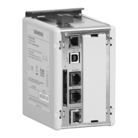
Page 7: Sitrans Rd500 Components
RD500 to provide remote data management functionality to these instruments. The RD500 is not limited to Siemens instruments but also readily accepts outputs from any of your existing instrument infrastructure that support the above mentioned I/O. -
Page 8: Specifications
Specifications For specifications of RD500 modules, please refer to RD500 hardware manuals, available at www.siemens.com/sitransRD500. Page 6 SITRANS RD500 – OPERATING INSTRUCTIONS 7ML19985MA01... -
Page 9: Sitrans Rd500 Application
Using simple menus, on-screen buttons, and drop-down lists, you can easily access any monitored instrument. The straightforward, consistent interface makes operation of SITRANS RD500 fast and convenient. As well, the configuration of the modules is easy and automatic, with no manual configuration required. - Page 10 The crossover Ethernet cable is used for a point-to-point network, while a Note: standard straight-through Ethernet cable is used in most LAN or WAN networks. Straight-through Ethernet cable can be used for direct connection if PC or laptop supports auto crossover detection. Page 8 SITRANS RD500 – OPERATING INSTRUCTIONS 7ML19985MA01...
- Page 11 Setting your PC’s IP address Go to the Windows Control Panel, and double-click Network Connections. Double-click Local Area Connection. 7ML19985MA01 SITRANS RD500 – OPERATING INSTRUCTIONS Page 9...
- Page 12 100 This may require a computer reboot to update your network settings. Be sure to close all open browser windows, before opening the RD500 application for the first time below. Page 10 SITRANS RD500 – OPERATING INSTRUCTIONS 7ML19985MA01...
- Page 13 Overview screen will be blank. LED activity will be visible on both your computer Ethernet port and on the Note: RD500 Ethernet port if your crossover cable is connected. 7ML19985MA01 SITRANS RD500 – OPERATING INSTRUCTIONS Page 11...
-
Page 14: Screen Appearance
If the display exceeds screen size, use the scroll bars to see additional content. Screen Layout user defined site name date and time programming menu bar data overview screen Page 12 SITRANS RD500 – OPERATING INSTRUCTIONS 7ML19985MA01... - Page 15 "no", I/Os will not be displayed.) • the current value (PV) of the device • the status of the PV relative to the programmed alarm values 7ML19985MA01 SITRANS RD500 – OPERATING INSTRUCTIONS Page 13...
- Page 16 Logs page by selecting the checkbox to the left of the file, and clicking Delete Selected. Event Logs Event logs record system information. The various events recorded to CompactFlash are explained below: POWER ON - System powered up. STOPPED - System stopped for config update. Page 14 SITRANS RD500 – OPERATING INSTRUCTIONS 7ML19985MA01...
- Page 17 After factory reset, the event log will be erased and some data log files may Note: be overwritten. Be sure to backup your data log files before any factory reset. 7ML19985MA01 SITRANS RD500 – OPERATING INSTRUCTIONS Page 15...
- Page 18 In addition to using the RD500’s built-in FTP client to send data to an external FTP server, the SITRANS RD500 also has a built-in FTP Server allowing external FTP clients to access data on the RD500's CompactFlash card. To enable this, click Enable Server and select if FTP Server you wish to support anonymous or unsecured access.
-
Page 19: General Configuration
CF card). • To set the Time and Date fields, edit the Time or Date field in question, then check the Set Time checkbox, and then click Apply. 7ML19985MA01 SITRANS RD500 – OPERATING INSTRUCTIONS Page 17... -
Page 20: Network Configuration
MAC address associated with the unit, as otherwise, users will not be sure how to address the RD500. Under Mode, if Ethernet is disabled, the ethernet access port will no longer be Page 18 SITRANS RD500 – OPERATING INSTRUCTIONS 7ML19985MA01... - Page 21 Firewall sets the modem to dial including a firewall. Dial Out Client sets the modem to dial without a firewall. Dial In Server allows outside applications to dial in to access the SITRANS RD500 as a server. When using a GPRS modem, set the MODE field to Dial Out Client. For Note: details on setting up other modem types, refer to the modem app guide.
- Page 22 Permission levels Operator and Super User only have write access to these fields (see below). User must contact a local data plan provider for data plan options. Page 20 SITRANS RD500 – OPERATING INSTRUCTIONS 7ML19985MA01...
-
Page 23: Password And User Management
Password and User Management Access and Security Accessing SITRANS RD500 is the same as accessing any website. However, to ensure that your access is secure, you are required to enter your User Name and Password. User Management There are three levels of user for the SITRANS RD500: Basic: Read only access to RD500 data;... -
Page 24: Analog Input Modules - 0 To 10 V And 0 (4) - 20 Ma
RD500 I/O Configuration Any connected modules are automatically detected by the SITRANS RD500. Enter the pertinent information for any device connected to the installed modules. Module detection is carried out on power up, so removing old or inserting new modules with the power on is only permissible with modules of the same type. - Page 25 PV. This is useful in applications such as the measurement of flow with a differential pressure transducer. • The Log property is used to select the log file into which the channel's data is recorded. 7ML19985MA01 SITRANS RD500 – OPERATING INSTRUCTIONS Page 23...
-
Page 26: Digital Module
The Mode property defines whether the low or high state of the input is to be considered active. • The Log property is used to select the log file into which the channel's data is recorded. Page 24 SITRANS RD500 – OPERATING INSTRUCTIONS 7ML19985MA01... -
Page 27: Temperature Input Modules (Tc/Rtd)
The Log property is used to select the log file into which the channel's data is recorded. • The View property is used to set the display of the channel’s information in the overview screen. 7ML19985MA01 SITRANS RD500 – OPERATING INSTRUCTIONS Page 25... -
Page 28: Application Example
Modbus slave device to respond. If the Modbus master does not receive a response from the slave in the specified time, the master will enter a timeout error in the event log. Page 26 SITRANS RD500 – OPERATING INSTRUCTIONS 7ML19985MA01... -
Page 29: Configuring Modbus I/O
The Type property defines the data type of the slave's data, including Bit, Word, Long, and Real. Bits are packed into registers in groups of 16 bits (1 word). • The Access property defines the registers as read-only, write-only, or read and write. 7ML19985MA01 SITRANS RD500 – OPERATING INSTRUCTIONS Page 27... - Page 30 • The Log property is used to select the log file into which the channel's data is recorded. After adding Configuration information, click Apply to write changes to the RD500. Page 28 SITRANS RD500 – OPERATING INSTRUCTIONS 7ML19985MA01...
- Page 31 Choose Scaling to allow your raw data from your Modbus device to be scaled into realistic useful values using the SITRANS RD500. • The Address specifies the starting Modbus register address to be polled. • The Tag property allows a descriptive name to be applied to the I/O channel, e.g.
-
Page 32: Data Log Configuration
A 1 GB CF card is included with the SITRANS RD500 and an optional 2GB card is available for order. From the Overview page, click Configure and then Logs to create and edit the logging facility. -
Page 33: Log File Storage
YYMMDD10.csv (samples starting from 10:00) Log entries will be written to on-board buffer memory first, and then will be Note: copied to the CompactFlash memory. Buffer memory is written to the CF card every two minutes. 7ML19985MA01 SITRANS RD500 – OPERATING INSTRUCTIONS Page 31... -
Page 34: Accessing The Server
For anonymous access: to access an FTP server from a web browser, type ftp://192.168.200.1 (replace 192.168.200.1 with your unit IP address). For secure access: to access an FTP server from a web browser securely, type ftp://admin:rd500@192.168.200.1 (replace 192.168.200.1 with your unit IP address). Page 32 SITRANS RD500 – OPERATING INSTRUCTIONS 7ML19985MA01... - Page 35 GPRS. • The Base Directory defines the directory on the server where the log files will be synchronized. This directory is relative to the folder settings given in the FTP server. 7ML19985MA01 SITRANS RD500 – OPERATING INSTRUCTIONS Page 33...
-
Page 36: Configuring Mail And Sms Notification
The Push Logs Now checkbox allows the user to force log synchronization. This is useful when commissioning and testing systems. Click Apply to write any changes to the SITRANS RD500. Configuring Mail and SMS Notification The RD500 provides alarm notification via email and SMS text messages. Notification can be sent to a single recipient, or a group of recipients. - Page 37 • The SMS field is used to enter short message service cellular phone number. (Enter phone number without spaces or hyphens.) 7ML19985MA01 SITRANS RD500 – OPERATING INSTRUCTIONS Page 35...
-
Page 38: Configuring Reports
Method property indicates whether the report will be sent via Email or FTP or both. • Send Logs property determines whether to include the last datalog or event log with the report. • Send Now sends the report immediately. Page 36 SITRANS RD500 – OPERATING INSTRUCTIONS 7ML19985MA01... -
Page 39: Appendix A: Input Modules
Protocol Type = Modbus RTU and Modbus ASCII • RTU Framing = Detect via Timing • Slave Response Timeout = 1000 • Baudrate = selectable • Databits = 1 • Parity = None • Stopbits = 1 7ML19985MA01 SITRANS RD500 – OPERATING INSTRUCTIONS Page 37... -
Page 40: Modbus And Siemens Instruments
Port 1 setup parameters: Parameter Description P751 = 3 baud rate selectable P752 = 0 no parity P753 = 1 address 1 to 247 P758 = 0 interframe spacing = 0 ms Page 38 SITRANS RD500 – OPERATING INSTRUCTIONS 7ML19985MA01... -
Page 41: Wiring Diagram To Connect To Sitrans Lu With Smartlinx® Modbus Rtu Card
*(2) refers to the primary index (secondary index 0). Wiring Diagram to Connect to MultiRanger 100/200 and the HydroRanger 200 Connecting the communication cable to the MultiRanger 100/200 or HydroRanger 200. RD500 RS-485 (RJ45) 7ML19985MA01 SITRANS RD500 – OPERATING INSTRUCTIONS Page 39... -
Page 42: Sitrans Luc500
Wiring Diagram to Connect to SITRANS LUC500 Connecting the communications cable to the SITRANS LUC500 wall mount: RD500 RS-485 (RJ45) Connecting the communications cable to the SITRANS LUC500 Rack Mount RD500 RS-485 (RJ45) Page 40 SITRANS RD500 – OPERATING INSTRUCTIONS 7ML19985MA01... -
Page 43: Wiring Diagram To Connect To Milltronics Bw500
If you are using Belden 9842 cable, the value for termination is 120R, 0.5 W resistor. Bus termination resistors to be 120R. Recommended cable is Belden 9842. 7ML19985MA01 SITRANS RD500 – OPERATING INSTRUCTIONS Page 41... -
Page 44: Optional Connector Wiring
Optional Connector Wiring RJ45 Serial to Terminal Block RS-485 (7ML1930-1FE) RJ45 serial to terminal block RS-485 (7ML1930-1FE) Page 42 SITRANS RD500 – OPERATING INSTRUCTIONS 7ML19985MA01... -
Page 45: Wiring Diagram To Sitrans P Dsiii Via 4-20 Ma Connection
Wiring Diagram to SITRANS P DSIII via 4-20 mA connection power supply SITRANS P DS III 24 V DC Wiring Diagram to MultiRanger 100/200 via 4-20 mA connection Wiring Diagram to SITRANS LR460 via 4-20 mA connection mA output 7ML19985MA01 SITRANS RD500 – OPERATING INSTRUCTIONS Page 43... -
Page 46: Wiring Diagram To Sitrans Lr250 Via 4-20 Ma Connection
Wiring Diagram to SITRANS LR250 via 4-20 mA connection power supply SITRANS LR250 24 V DC PT100 wiring PT100 Thermocouple TC module wiring for J Type Thermocouple J Type Thermocouple Page 44 SITRANS RD500 – OPERATING INSTRUCTIONS 7ML19985MA01... -
Page 47: For More Information
For more information www.siemens.com/level www.siemens.com/weighing Siemens AG Subject to change without prior notice Industry Sector 7ML19985MA01 Rev. 1.3 1954 Technology Drive P.O. Box 4225 *7ml19985MA01* © Siemens AG 2011 Peterborough, ON Canada K9J 7B1 Printed in Canada email: techpubs.smpi@siemens.com www.siemens.com/processautomation...