Table of Contents
Advertisement
Quick Links
Advertisement
Table of Contents

Related Manuals for Daewoo DVG-6000D


Summary of Contents for Daewoo DVG-6000D
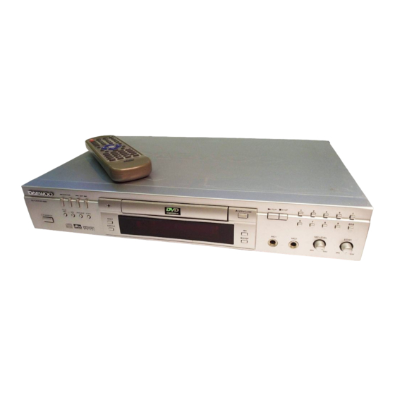
- Page 1 DVD PLAYER DVG-6000D...
-
Page 2: Table Of Contents
CONTENTS 1. PRECAUTIONS------------------------------------------------------------------------------------------------------------------------1 1-1 S -------------------------------------------------------------------------------------------------------------1 AFETY RECAUTIONS 1-2 S ---------------------------------------------------------------------------------------------------------2 ERVICING RECAUTIONS 1-2-1 General Serving Precautions------------------------------------------------------------------------------------------------2 1-2-2 Insulation Checking Procedure ---------------------------------------------------------------------------------------------3 1-3 ESD P ----------------------------------------------------------------------------------------------------------------3 RECAUTIONS 2. REFERENCE INFORMATION ------------------------------------------------------------------------------------------------------4 2-1 C ------------------------------------------------------------------------------------------------------4 OMPONENT ESCRIPTIONS 2-1-1 DVD ATAPI Loader ---------------------------------------------------------------------------------------------------------4 2-1-2 NTSC/PAL Digital Video Encoder (AV3168) ----------------------------------------------------------------------------6 2-1-3 DVD Processor Chip (Swan-2 ES4318)------------------------------------------------------------------------------ 10... -
Page 3: Precautions
1. Precautions 1-1 Safety Precautions 1) Before returning an instrument to the customer, always make a safety check of the entire instrument, including, but not limited to, the following items: (1) Be sure that no built-in protective devices are defective or have been defeated during servicing. -
Page 4: Servicing Precautions
notes non or inside the cabinet, or on the chassis. 5) Components, parts, and/or wiring that appear to have overheated or that are otherwise damaged should be 3) Design Alteration Warning-Do not alter of add to the replaced with components, parts and/or wiring that mechanical or electrical design of this instrument. -
Page 5: Insulation Checking Procedure
components, and wiring have been installed correctly turn the power ON. Connect the insulation resistance meter and that the portion around the serviced part has not (500V) to the blades of the attachment plug. The insulation been damaged and so on. Further, check the insulation resistance between each blade of the attachment plug and between the blades of the attachment plus and accessible conductive parts (see note) should be more than... -
Page 6: Reference Information
2. Reference Information 2-1 Component Descriptions 2-1-1 DVD ATAPI Loader D.C. Power Supply A 4-pin shrouded, keyed male connector is used to provide the D.C.Power. The pin assignment is described below. DC VOLTS +12V Interface Connector A 39-pin male, unshielded, shrouded, keyed connector are applied. Please refer to Section 7-2-3 regarding its pin definition. - Page 7 I/F Signals I/O Pin # I/F Signals I/O Pin # DD12 IOCS16 DD13 PDIAG DD14 CS1FS DD15 CS3FS DASP 4. Block Diagram...
-
Page 8: Ntsc/Pal Digital Video Encoder (Av3168)
2-1-2 NTSC/PAL Digital Video Encoder (AV3168) • Contrast and Brightness control. FEATURES • Fully CCIR 624 performance compliance NTSC and Clock Generation PAL (B,D,G,H,I,M and N) video encoder. • 3 outputs for 27 MHz video clock, 16.934, 18.432 and • Composite, S-video, Component Y/Cb/Cr (Sony, 36.864 Mhz audio clock, and 40.5, 54.0, 67.5 and Matsushita, and SMPTE) or RGB output. - Page 9 The Clock Generator outputs three clocks for video, audio and system to simplify the system configuration and maintain A/V synchronization. Typical Application Connection AV3168 Detailed Block Diagram...
- Page 10 PIN DESCRIPTIONS Pin Name Pin # Type Description DIGITAL VIDEO INPUT 11-16 PD<7 -0> Multiplexed Cb, Y, and Cr digital video input bus. 18-19 In Slave Mode (MSTR pin is low) Horizontal Synch input. In Master HSYN Mode (MSTR pin is high) Horizontal Synch output. In slave mode (MSTR pin is low) Vertical Sync input.
- Page 11 Pin Name Pin # Type Description Cr output in CbCr component mode Blue color output in RGB mode Analog video output Determined by the state of CPNT pin and CR0[5:4] CPNT CR0[5] CR0 [4] S-Video Y output. Cb output in CbCr component mode R color output in RGB mode Analog video output Determined by the state of CPNT pin and CR0[5:4]...
-
Page 12: Dvd Processor Chip (Swan-2 Tm Es4318)
Pin Name Pin # Type Description GCK frequency select pin when is low. General purpose output pin when is high Dual function pin. GCK frequency select pin when is low. General purpose output GOUT0 pin when is high POWER AND GROUND 10, 22, Digital power supply 8, 17,... - Page 13 * Functional Description...
- Page 14 * Pinout Diagram...
- Page 15 * PIN DESCRIPTON Name Number Definition 1, 9, 18, 27, 35, 44, 51, 59, 68, 75, 83, 92, 99, 104, 111, 3.65 V ± 150 mv. 121, 130, 139, 148, 157, 164, 172, 183, 193, 201 LA[21:0] 23:19, 16:10, 7:2, 207:204 Device address output 8, 17, 26, 34, 43, 52, 60, 67, 76, 84, 91, 98, 103, 112, 120, 129, 138,...
-
Page 16: 8-Pin, 24-Bit, 96Khz Stereo D/A Converter (Cs4338)
Name Number Definition active low. HD[15:0] 141:140, 137:131, 128:122 Host data bus HCS1FX# Host select 1. HCS3FX# Host select 3. HIOCS16# Device 16-bit data transfer. HA[2:0] 158, 155:154 Host address bus. Peripheral protection voltage. HWR#/DCI_ Host write/DCI interface Acknowledge ACK# Signal, active low. -
Page 17: Serial Eeprom, 2K (256 X 8) (At24C02/01)
PIN DESCRIPTIONS 2-1-5 Serial EEPROM, 2K (256 x 8) (AT24C02/01) * Features Low-Voltage and Standard-Voltage Operation -5.0 (V CC = 4.5V to 5.5V) -2.7 (V CC = 2.7V to 5.5V) -2.5 (V CC = 2.5V to 5.5V) -1.8 (V CC = 1.8V to 5.5V) -
Page 18: 4-Megabit (512 X 8) Flash Ram (Mx29F040)
Internally Organized 128 x 8 (1K), 256 x 8 (2K), 512 x 8 (4K), 1024 x 8 (8K) or 2048 x 8 (16K) 2-Wire Serial Interface Schmitt Trigger, Filtered Inputs for Noise Suppression Bi-directional Data Transfer Protocol 100 kHz (1.8v, 2.5V, 2.7V) and 400 kHz (5V) Compatibility Write Protect Pin for Hardware Data Protection 8-Byte Page (1K, 2K), 16-Byte Page (4K, 8K, 16K) Write Modes Partial Page Writes Are Allowed... -
Page 19: 512K X 16 Bit X 2 Banks Synchronous Dram (A43L0616)
Integrated Product Identification Code Commercial and Industrial Temperature Ranges * Pin Configurations * Pin Description Pin Name Function A0 – A18 Addresses O0 – O7 Outputs Chip Enable Output Enable * Absolute Maximum Ratings Temperature Under Bias………………………….-55 C to + 125 Storage Temperature……………………………...-65 C to + 150 Voltage on Any Pin with Respect to Ground……..-2.0V to + 7.0V... - Page 20 All inputs are sampled at the positive going edge of the system clock Burst Read Single-bit Write operation DQM for masking Auto & self refresh 64ms refresh period (4K cycle) 50 Pin TSOP (II) Pin Configuration...
- Page 21 Block Diagram Pin Descriptions Symbol Name Description System Clock Active on the positive going edge to sample all inputs Chip Select Disables or Enables device operation by masking or enabling all inputs except CLK, CKE and L(U)DQM Masks system clock to freeze operation from the next clock cycle. Clock Enable CKE should be enabled at least one clock + tss prior to new command.
- Page 22 Symbol Name Description Makes data output Hi-Z, t SHZ after the clock and masks the output. L(U)DQM Data Input/Output Mask Blocks data input when L(U)DQM active. DW0-15 Data Input/Output Data inputs/outputs are multiplexed on the same pins. VDD/VSS Power Supply/Ground Power Supply: +3.3V±0.3V/Ground Data Output VDDQ/VSSQ...
-
Page 23: Product Specifications
3. Product Specifications Playback System DVD Video Video CD (1.1, 2.0, 3.0) SVCD and CVD CDDA CD-ROM with MP3 data Television Signal System NTSC/PAL Video Performance Video Out 1 Vpp into 75 ohm S-Video Out Y: 1Vpp into 75 ohm C: 0.286 Vpp into 75 ohm Component Out 0.7 Vpp into 75 ohm... -
Page 24: Operating Instructions
4. Operating Instructions 4-1 Basic Connections * CONNECTED TO A TV * CONNECTED TO AN ORDINARY AMPLIFIER 4-2 Selecting Video MODE Press SETUP button and select GENERAL SETUP submenu on SETUP screen. After that, select TV TYPE by pressing DOWN arrow button (▼ ) until desired TV mode is selected. For more information, refer to Page 34-36 on the Instruction Manual. -
Page 25: Selecting The Desired Dvd Menu Item
4-3 Selecting the desired DVD menu Item Some DVDs have title menus and chapter menus. Press MENU or TITLE,the screen shows the menu.Then use direction buttons to select the desired item,press PLAY. 4-4 Selecting the desired MP3 folder Use arrow button to select the folder you want to play. Then by pressing the PLAY button ,you can see the the file lists under the folder. -
Page 26: Selecting Subtitle Language
4-8 Slow Viewing When you want to view the disc contents very slowly in forward or reverse direction, you can do that by pressing the SLOW button. When playing DVD,there are six choices:SF2X, SF4X, SF8X, SR2X, SR4X, SR8X. While playing SUPER-VCD OR VCD,there are three choices: SF1x, SF2x, SF3x.Take DVD for example, to view at slow 2x in reverse direction ,press the slow buttom four times. -
Page 27: Disassembly And Reassembly
5. Disassembly and Reassembly... -
Page 28: Troubleshooting
6. Troubleshooting No power Insert the AC power plug securely into the power outlet. Make sure that the equipment is connected properly. No picture Make sure that the input setting for TV is Video (AV). No sound Make sure that the equipment is connected properly. Distorted sound Make sure that the input settings for the TV and stereo system are correct. -
Page 29: Electrical Part List
FUSS DVD loader JX-JXFUSS bracket of loader WJ-JXZJ930E5 the height of HPT loader: 17.5mm Two-channel decoding sub- GV-DJH930 BC-PDJH930-03 with microphone and s-video output assembly for DAEWOO DVD GV-DPA868 subassembly GV-DPA868 BC-PDPA86801 10/20/2k Interface subassembly of SCART BC-PSCART02 2001-3-28 930E2 motherboard... - Page 30 Name Counts Blueprint No. Material No. Notes sticker for DVD trademark SJ-DVDSBP with background black and characters silvery 2 for decodeing board 6 for power-supply strut for circuit board SJ-XLBJZ-01(new) board plastic nut cap SJ-XLBJZ-02(new) decodeing board 2 power-supply board 6 970 rubber mat SJ-VCDJJD2MM thickness 2mm...
- Page 31 Name Counts Blueprint No. Material No. Notes round-headed self-fastened hardened nailBTV3*16 LD-BTV3*16C power-supply board: 6 decoding board: 2 colorful zinc plain-headed triangular nail 2 for component and audio output 2 for scart LD-BB3*8C colorful zinc board acute-headed nail BA3*8 colorful LD-BA3*8C for coaxial output zinc...
- Page 32 The list for cover subassembly design of DVG6000D Name Counts Blueprint No. Material No. Notes trademark GV-SBPDAEWOO WJ-SBPHDYZDAEWOO01 DAEWOO silk-screen file No.: DVG6000D panel GV-MB930 SJ-MB6000D GV-MB6000D DV930 power-supply button GV-DYN930-01 SJ-DYN930 silver GV320S knob GV-DWQXN320-01 SJ-XN320 silver number button...
- Page 33 The components design list for control panel Name/Specification Counts Position in the paper Material No. Notes resistor resistor 220E 1/4W DZ-RT220EYS resistor 10K 1/4W R2,R3,R4,R6,R7,R8,R9,R10D DZ-RT10KYS R10 connects IC16311 with the earth resistor 51K 1/4W DZ-RT51KYL porcelain capacitor porcelain capacitor 104 50V CC-104Z505 diameter: 5mm electrolyzed capacitor...
- Page 34 Name/Specification Counts Position in the paper Material No. Notes no-terminator gray row-wire PX-W240W8H from control board to LCDIC board 240mm 3.96connector 2P no-terminator 150 red from switch board to power-supply PX-E150W3R01 both-insulated board iron thread 5mm FJ-TX5MM diameter: 0.6mm iron thread 8mm J1, J2, J3, J5 FJ-TX8MM diameter: 0.6mm...
- Page 35 Name Counts Blueprint No. Material No. Notes 50V 10% electrolyzed capacitor electrolyzed capacitor 10UF C1,C2,C6,C7,C8,C10,C13,C14,C15,C16,C17,C18 CD-10UW165 diameter:5mm 16V 20% electrolyzed capacitor 100UF C5,C12 CD-101W165 diameter:5mm 16V 20% 11 IC JRC4558 IC1,IC2 IC-4558 triode 12 triode 2SC1815 Q1 Q2 MD-2SC1815350-650 β=350~650 accessories inserting hole for microphone CZ-HTCK03...
-
Page 36: Block Diagram
8. Block Diagram... -
Page 37: Circuit Diagrams
9. Circuit Diagrams Control Part Ear Part Video Part Scart Part Clock Part Memory Part Chip 4318 D/A Converter Part Atapi Part Audio Part Power Part... - Page 38 Control Part SEG20 6-B T-297GK SEG19 SEG18 R EMOTE SEG17 SEG16 SEG15 DOUT SEG14 SEG13 C LK SEG12 CON6 SEG11 SEG10 SE G9 SE G8 SE G7 SE G6 SE G5 SW 1 SE G4 SW 2 SE G3 SW 3 SE G2 SW 4 SE G1...
- Page 39 Ear Part C1815 R 30 1/ 2VCC 1. 5K 5. 6V C 32 1/ 2VCC *R b1 22uF/ 16V 2.2uF50V UJM4558 1/ 2VCC VR 1A 4. 7uF/ 16V C X1 R 11 1000P 1uF/ 50V UJM4558 A20K MIC1 10uF/ 16V UJM4558 C K-6.35 C 12...
- Page 40 Video Part V V CC TV CC F B5 + 5V V V CC F ERRI TE BEAD F B1 F ERRI TE BEAD 4 7 uF 0 .1 uF 0 .1 uF 1 0 0 uF 0 .1 uF 2 2 pF 4 .7 uH X H1...
- Page 41 Scart Part GND_POWER GND_POWER CONN RCPT 21/SM 10U/50V GND_POWER GND_POWER GND_POWER GND_POWER GND_POWER GND_POWER GND_POWER C1815 680E 12 HEADER 3.9K 10U/50V GND_POWER 100U/16V 680E GND_POWER C1815 A1015 HS 945P 10U/50V GND_POWER HS 945P GND_POWER GND_POWER COMPANY TITLE SCART FILE BC-PSCART02.DSN D05A SHEET SHEET 1 of 1...
- Page 42 Clock Part R1 51 ( OP EN) V CC C1 45 R1 69 1 0U /1 6V 3 3 0E R1 68 RS T# 1 0K R1 50 0 O HM 3 3 O HM JE9 0 14 2 7M D CLK R1 70 1 0K...
- Page 43 Memory Part V CC3 V CC3 DMA[ 0 ..11 ] V CC3 V CC3 DMA0 D B7 1 0 O HM D B[ 0 ..15 ] D Q0 D B7 D B6 D Q0 D Q1 DMA1 D B6 D B5 D Q1 D Q2 D B5...
- Page 44 Chip 4318 V CC3 V CC Ins ta ll R 10 0 for ES4308 TDMDX Insta ll R10 1 fo r ES43 18/ES4408 V CC R1 01 4 .7K TS D0 ES 4 3 18 O P EN R1 00 (4.7K) 1 05 D CLK...
- Page 45 D/A Converter Part VCCA1 U 18 CS 4 3 38 SD A TA R2 00 D EM/S CLK AO U TL VCCA1 V CCA LRCK C1 37 C1 36 10 0 UF 0 .1 UF MCLK AO U TR VCCA1 CLKO A UD CLK VO U TR...
- Page 46 Atapi Part DRS T# HRS T# 4 7 O HM DRS T# RES ET G ND DWR# DD 15 D D0 H W R# DD 14 D D1 4 7 O HM V CC V CC DD 13 D D2 D 10 DD 12 D D3...
- Page 47 Audio Part + 1 2V R1 96 1 0E +1 2 VA C1 68 1 0 0U /2 5V R1 98 1 0K C1 69 1 0 0U /1 6V 1/2 V CC C1 67 R1 97 1 0 0U /1 6V 1 0K 1 2V R2 01...
- Page 48 Power Part H E R 3 0 2 T 1 B YB YQDVD868 1 0 E C N3 AABB R T1 +S12V S12V T 2 A L 2 5 0 V C O N 1 V C C + 1 2 V 1 N4 0 05 20uH Z D1...
-
Page 49: Wiring Diagram
10. Wiring Diagram DVD-6000D WIRING DIAGRAM...