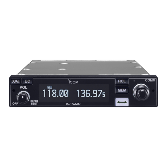
Icom IC-A220 Instruction Manual
Vhf air band transceiver
Hide thumbs
Also See for IC-A220:
- Instruction manual (40 pages) ,
- Installation manual (2 pages) ,
- Service manual (233 pages)
Table of Contents

Related Manuals for Icom IC-A220


Summary of Contents for Icom IC-A220
- Page 1 INSTRUCTION MANUAL VHF AIR BAND TRANSCEIVER iA220 A-7186D-1EX-3 • Certified TSO C128a and C169a • This device complies with Part 15 of the FCC Rules. Operation is subject to the condition that this device does not cause harmful interference.
-
Page 2: Fcc Information
Thank you for choosing this Icom product. • POUR LES RAYONNEMENTS NON INTENTIONNELS DE This product is designed and built with Icom’ s state of CLASSE A: the art technology and craftsmanship. With proper care, Cet équipement a été testé et reconnu conforme aux this product should provide you with years of trouble-free limites fixées pour un appareil numérique de classe A,... -
Page 3: Precautions
PTT when you do not actually intend not manufactured or approved by Icom. to transmit. Icom, Icom Inc. and Icom logo are registered trademarks of Icom Incorporated (Japan) in Japan, the United States, the United Kingdom, Germany, France, Spain, Russia, Australia, New Zealand, and/or other countries. - Page 4 PRÉCAUTIONS NE PAS R NE JAMAIS placer l'émetteur-récepteur dans des endroits utiliser l’émetteur-récepteur avec un excessivement poussiéreux. casque ou d’autres accessoires audio ayant un volume trop élevé. Un volume continu trop fort peut entraîner NE PAS nettoyer l'appareil avec des solvants agressifs un bourdonnement dans vos oreilles.
-
Page 5: Safety Training Information
Electromagnetic Interference/Compatibility the antenna as worst case, the antenna shall be During transmissions, your Icom radio generates RF energy located on the roof top at any place on the centre line that can possibly cause interference with other devices or along the vehicle in order to achieve 50 centimeters systems. -
Page 6: Information En Matière De Sécurité
Dans le pire des cas, pour un petit véhicule, l'antenne doit être placée sur le toit, n'importe où dans l'axe central du En mode de transmission, votre radio Icom produit de l'énergie de véhicule, afin de respecter une distance de 50 cm du bord le RF qui peut provoquer des interférences avec d'autres appareils ou... -
Page 7: Table Of Contents
TABLE OF CONTENTS IMPORTANT ................i 4 OTHER FUNCTIONS ..........13–16 FCC INFORMATION ............. i ■ Dualwatch operation ..........13 EXPLICIT DEFINITIONS ............i ■ Priority watch .............13 PRECAUTIONS ..............ii ■ Accessing the 121.5 MHz emergency frequency ..14 SAFETY TRAINING INFORMATION ........iv ■... -
Page 8: Panel Description
PANEL DESCRIPTION ■ Front panel COMM DUAL MEMORY 118.00 121.52 CH09 SAMPLE PUSH TEST q DUAL KEY [DUAL] e VOLUME/POWER SWITCH [VOL] ➥ Push to turn Dualwatch operation ON or OFF. (p. 13) ➥ Turn ON or OFF the transceiver. ➥... -
Page 9: Rear Panel
PANEL DESCRIPTION ■ Rear panel r FREQUENCY EXCHANGE (FLIP-FLOP) KEY [ ➥ Push to exchange the standby frequency with the active frequency. (p. 5) ➥ Hold down for two seconds to enter the direct frequency setting mode. (p. 6) t MEMORY KEY [MEM] Hold down for 2 seconds to enter the displayed frequency into any blank regular memory channel or clear or revive the selected memory channel (depending on the... -
Page 10: Function Display
PANEL DESCRIPTION ■ Function display y MEMORY TYPE READOUT ➥ Displays “MEMORY” when the regular memory channel is selected. (p. 8) DUAL MEMORY ➥ Displays “GRP01”–“GRP05” when the group 118.00 121.52 memory channel is selected. (p. 8) The group name is also displayed if the name has TEST CH09 SAMPLE been entered. -
Page 11: Basic Operation
BASIC OPERATION ■ General description The flow chart below shows the basic operating procedures. Set the frequency normally You need to set the frequency, activate the frequency, and Set the frequency which will be used for the next operating receive or transmit. frequency in the standby frequency display. -
Page 12: Receiving And Transmitting
BASIC OPERATION ■ Receiving and transmitting 1. Setting the standby frequency 3. Receiving Rotate [DIAL] and [O-DIAL] to set the standby frequency. While receiving a signal, “RX” is displayed and audio is • The active frequency is not affected. heard. •... -
Page 13: Directly Setting The Frequency
BASIC OPERATION ■ Directly setting the frequency ■ Squelch settings D Adjusting the squelch You can also directly set the frequency. Adjust the squelch to mute the noise when no signal is received. q Hold down [ ] for 2 seconds to enter the direct frequency setting mode. -
Page 14: Memory Operation
MEMORY OPERATION ■ General description The transceiver has memory to store frequently used D Memory channel types frequencies. You can easily set the frequency by selecting the channel from the memory. Regular memory channels (MEMORY) The table below shows the structure of the memory mode. Up to 20 memory channels can be selected. -
Page 15: Basic Operation
MEMORY OPERATION ■ Basic operation ■ Editing Regular memory/Group memory channels q Push [RCL] to enter the MEMORY 118.00 127.00 memory mode. D Memory mode menu • The memory channel number is CH01 There are memory mode menus to edit the memory displayed. -
Page 16: Clearing The Memory Contents
MEMORY OPERATION D Enter frequencies into memory channels D Clearing the memory contents To enter frequencies into memory channels, follow the steps You can clear unwanted memory channels. below. q Push [RCL] to enter the memory mode. q Rotate [DIAL] and [O-DIAL] to set the standby frequen- •... -
Page 17: Entering Group Names
MEMORY OPERATION D Entering group names D Entering channel names (For only group memory channels) (For only regular memory channels) The memory groups can display a six character name in The regular memory channels can display a six character addition to the group number (“GRP01”–“GRP05”). name in addition to the memory number. - Page 18 MEMORY OPERATION D Selecting channel tag names (For only group memory channels) Channel tag list The tag name can be set to a three character name, in DISPLAY MEANS addition to the group number. It is convenient for separating NAME Group* memory types.
-
Page 19: Selecting A Weather Memory Channel
MEMORY OPERATION ■ Selecting a weather memory ■ History memory channel channel The transceiver has 20 history memory channels. When pushing [ ], the active frequency is stored into a q Push [RCL] to enter the memory mode. history memory channel. w Rotate [O-DIAL] to select “WEATHER.”... -
Page 20: Other Functions
OTHER FUNCTIONS ■ Dualwatch operation ■ Priority watch The Dualwatch operation alternately monitors the active If a signal is detected on the standby frequency while frequency and standby frequency at certain intervals, while Dualwatch operation with the Priority watch is enabled no signal is detected on either frequency. -
Page 21: Accessing The 121.5 Mhz Emergency Frequency
OTHER FUNCTIONS ■ Accessing the 121.5 MHz ■ Enabling the intercom emergency frequency When two headsets are connected to the transceiver, you can use them as a voice-activated intercom. The transceiver can be set to the 121.5 MHz emergency frequency immediately. q While holding down [DUAL], rotate [VOL] to turn ON the transceiver power. -
Page 22: Setting The Frequency Step
OTHER FUNCTIONS ■ Setting the frequency step ■ Scanning the weather memory channels You can select Frequency steps of 8.33 kHz or 25 kHz in the menu mode. Scanning automatically searches for weather channel signals. q Hold down [RCL] for two seconds to enter the Settings Repeatedly scans all weather memory channels. -
Page 23: Low Voltage Indicator
OTHER FUNCTIONS e While receiving a signal on the weather channel: • “RX” blinks on the standby frequency display and the scan is cancelled. • “DUAL” is displayed on the active frequency display. DUAL WEATHER 122.00 161.65 WX08 r When no signal is received on any weather channels: •... -
Page 24: Menu Mode
MENU MODE ■ Using the menu mode • Settings menu items You can customize the transceiver settings to suit your Item Ref. Item Ref. preferences and operating style. There are two types of menu mode, Settings menu and SQL LEVEL p. - Page 25 MENU MODE • Configuration menu items D Using the Configuration menu Item Ref. Item Ref. q While holding down [DUAL], rotate [VOL] to turn ON the transceiver’s power. AUTO SQL p. 21 DISP HIGH p. 23 • Configuration menu is displayed. AUTO SQL SW p.
-
Page 26: Settings Menu Items
MENU MODE ■ Settings menu items D AM squelch level “SQL LEVEL” D Intercom 1 microphone audio input level “INCOM LV1” Adjusts the squelch level for the AM mode operation. In order to receive signals properly, the squelch must be Sets the intercom 1 microphone input level. - Page 27 MENU MODE D Setting microphone 1 Gain “MIC1 GAIN” D External input level “AUX LEVEL” Sets microphone 1’s gain. Sets the external input level. • –010 to 010: Sets the microphone 1’s gain to between –10 and 10. • OFF (0): The external input is disabled.
-
Page 28: Configuration Menu Items
MENU MODE ■ Configuration menu items D Auto squelch “AUTO SQL” D Dualwatch interval “DW INTERVAL” Sets the interval time during Dualwatch or weather scan. Sets the Auto squelch function. • FAST: The interval is set to 300 milliseconds. • OFF: The Auto squelch is OFF. -
Page 29: Group Memory Channel Display
MENU MODE D Dimmer auto mode “DISP AUTO” D Group memory channel display Sets the method to automatically control the dimmer “GRP MEMORY” brightness. Selects whether the label is displayed or not. • PHOTO: Controls the dimmer brightness by using the light •... - Page 30 MENU MODE D External input “AUX IN” D Dimmer brightness (High) “DISP HIGH” Sets the audio usage input from an external audio device. Sets the maximum brightness level in the automatic Refer to ‘INSTALLATION GUIDE’ for the connection. adjustment range. •...
-
Page 31: Menu Mode
MENU MODE D Remote incom “REM INCOM” D Time-Out-Timer “TIME OUT” Sets the remote control (p. 15) to use the intercom or not. To prevent accidental prolonged transmission, the • OFF: The remote control for the intercom is OFF. transceiver has a time-out-timer. The function inhibits •... -
Page 32: Specifications
SPECIFICATIONS In Canada, use of 8.33 kHz Channel Spacing of this radio is strictly prohibited and shall not be used. D General D Transmitter • Frequency range: • Classes: 4 and 6 Channel spacing: 25 kHz 118.000 to 136.975 MHz •... -
Page 33: Information
• Channel spacing: 25 kHz (Actual frequency is displayed.) TSO/ETSO Deviation Operating Frequency Channel spacing Channel ID 1. Icom was granted a deviation from the TSO (MHz) (kHz) (Displayed Frequency) to mark the exterior of the unit with the serial 118.0000 118.000... -
Page 34: Index
INDEX AM squelch level ..............19 Emergency frequency............14 Automatic noise limiter ............19 Enter frequencies into memory channels ......9 Auto squelch ...............21 Entering channel names .............10 Entering group names ............10 External dimmer control............22 External input..............23 Basic operation ..............4 External input gain ..............23 Beep tone level ..............20 External input level .............20 Channel tag ................ - Page 35 INDEX Intercom................14 Setting menu items .............19 Intercom 1 microphone audio input level ......19 Setting microphone 1 Gain ..........20 Setting microphone 2 Gain ..........20 Intercom 1 squelch level .............21 Intercom 2 microphone audio Input level......19 Settings menu..............17 Intercom 2 squelch level .............21 Sidetone level ..............20 Intercom usable setting ............23 Squelch for test..............14...
- Page 36 Printed in Japan 2016–2017 Icom Inc. © Basic Issue: May 09/16 Revision 3: Feb 09/17 12421 Willows Road NE, Kirkland, WA 98034, U.S.A Printed on recycled paper with soy ink.