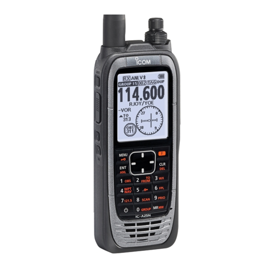
Icom IC-A25N User Manual
Vhf air band transceivers
Hide thumbs
Also See for IC-A25N:
- Service manual (90 pages) ,
- Basic manual (24 pages) ,
- Navigation manual (4 pages)
Table of Contents
Advertisement
Quick Links
FULL MANUAL
VHF AIR BAND TRANSCEIVERS
iA25N
iA25C
iA25NE
iA25CE
INTRODUCTION
1 ACCESSORIES ATTACHMENTS
2 PANEL DESCRIPTION
3 BATTERY CHARGING
4 BASIC OPERATIONS
5 VOR NAVIGATION
(For only the IC-A25N and IC-A25NE)
6 WAYPOINT NAVIGATION
(For only the IC-A25N and IC-A25NE)
7 SCAN OPERATION
8 MEMORY OPERATION
9 OTHER FUNCTIONS
10 Bluetooth
®
OPERATION
(For only the IC-A25N and IC-A25NE)
11 MENU ITEMS
12 SPECIFICATIONS AND OPTIONS
13 TROUBLESHOOTING
INDEX
Advertisement
Chapters
Table of Contents

Related Manuals for Icom IC-A25N


Summary of Contents for Icom IC-A25N
- Page 1 1 ACCESSORIES ATTACHMENTS 2 PANEL DESCRIPTION 3 BATTERY CHARGING 4 BASIC OPERATIONS VHF AIR BAND TRANSCEIVERS 5 VOR NAVIGATION iA25N (For only the IC-A25N and IC-A25NE) iA25C 6 WAYPOINT NAVIGATION (For only the IC-A25N and IC-A25NE) iA25NE 7 SCAN OPERATION iA25CE...
- Page 2 IC-A25N and IC-A25NE. Icom, Icom Inc. and the Icom logo are registered trademarks of Icom Incorporated (Japan) in Japan, the United States, the United Kingdom, Germany, France, Spain, Russia, Australia, New Zealand and/or other countries.
-
Page 3: Table Of Contents
Section ACCESSORIES ATTACHMENTS Supplied accessories ............1-2 Attaching accessories ............1-3 D Antenna .................1-3 D Battery pack/Battery case .............1-3 D Belt clip ..................1-4 Headset connection ..............1-5... -
Page 4: Accessories Attachments
ACCESSORIES ATTACHMENTS Supplied accessories Antenna Belt clip Handstrap Battery case Battery pack Headset adapter Power adapter* Battery charger* * May not be supplied, or the shape may be different, depending on the transceiver version. -
Page 5: Attaching Accessories
ACCESSORIES ATTACHMENTS Attaching accessories D Antenna Connect the supplied antenna to the antenna connector. CAUTION: • DO NOT carry the transceiver by holding only the antenna. • DO NOT connect an antenna other than supplied antenna or those listed in this manual. •... -
Page 6: D Belt Clip
ACCESSORIES ATTACHMENTS Attaching accessories (Continued) D Belt clip Belt clip To attach: 1. Remove the battery pack from the transceiver, if it is attached. 2. Slide the belt clip in the direction of the arrow until the belt clip is locked and makes a ‘click’ sound. To detach: Lift the tab up (q), and slide the belt clip in the direction of the arrow (w). -
Page 7: Headset Connection
ACCESSORIES ATTACHMENTS Headset connection Connect your headset through the supplied headset adapter. Use the Side Tone function to output your transmitted voice to the headset ([MENU] > Sounds Settings > Side Tone). (p. 11-7) PTT switch (User supplied, if necessary) Use a PTT switch with a 3.5 mm (1/8 inch) plug. - Page 8 Section PANEL DESCRIPTION Front, top and side panels (IC-A25C/IC-A25CE)* ....2-2 Function display ..............2-3 D Icon area ................2-3 D Text area ................2-3...
-
Page 9: Front, Top And Side Panels (Ic-A25C/Ic-A25Ce)*
Push [F], and then push this key to turn the * There are some keys and functions for only the IC-A25N Automatic Noise Limiter (ANL) function ON or and IC-A25NE. See page 5-2 for details. -
Page 10: Function Display
Displayed when the VOX function is ON. Memory mode. Bluetooth ® ICON (p. 10-2) (For only the IC-A25N and IC-A25NE) Displayed when a Bluetooth device is connected. WX ICON (For only the IC-A25N and IC-A25C) z “ ” is displayed when the transceiver is in the Weather Channel Selection mode. -
Page 11: Battery Charging
Section BATTERY CHARGING Battery charger ..............3-2 Battery case ................3-2... - Page 12 BATTERY CHARGING Battery charger Battery case You can charge the supplied battery pack using the When using the supplied battery case*, install 6 × AA supplied battery changer and power adapter. (LR6) size Alkaline batteries, as shown below. z Charging time: approximately 3 hours. L You can also use the optional CP-20 cigarette lighter cable, instead of the supplied battery charger and power adapter.
- Page 13 Section BASIC OPERATIONS Receiving and transmitting ..........4-2 D Setting the frequency ............4-2 D Receiving ................4-2 D Adjusting the squelch level ............4-2 D Using the Automatic Noise Limiter (ANL) function ....4-2 D Transmitting ................4-2 Selecting the 121.5 MHz emergency frequency....4-3 Selecting the Recall channels ..........
-
Page 14: Basic Operations
BASIC OPERATIONS Receiving and transmitting D Setting the frequency D Adjusting the squelch level L If the transceiver is in the Memory mode, push [CLR] to z Push [SQL∫] or [SQL√] to adjust the squelch level exit the Memory mode. until the noise just disappears, when no signal is z Use the keypad to set the frequency. -
Page 15: Selecting The 121.5 Mhz Emergency Frequency
BASIC OPERATION Selecting the 121.5 MHz Selecting the Recall channels emergency frequency The transceiver stores the previously selected frequencies in the “Recall CH.” You can easily select In case of emergency, you can immediately select the them without rotating [DIAL] or accessing memory. 121.5 MHz emergency frequency. - Page 16 Section VOR NAVIGATION (For only the IC-A25N and IC-A25NE) Keys used for Navigation Function ........5-2 Course Deviation Indicator (CDI) screen......5-2 Using the Omni Bearing Selector (OBS) ......5-2 Flying to a VOR station ............5-3 D Crosschecking position ............5-4...
-
Page 17: Vor Navigation
Course Deviation Indicator Keys used for (CDI) screen Navigation Function The IC-A25N and IC-A25NE have the keys shown The transceiver displays the CDI screen when the below to use the VOR Navigation function and NAV band frequency is selected. Waypoint Navigation function. -
Page 18: Flying To A Vor Station
• “TO 066” is displayed, and OBS is set to 066. 5. Maintain the heading that the Course Deviation Needle comes to the center of CDI. NOTE: The IC-A25N and IC-A25NE’s VOR Navigation features are supplemental aids to navigation only, and are not intended to be a... -
Page 19: D Crosschecking Position
VOR NAVIGATION Flying to a VOR station (Continued) THE AIRCRAFT IS ON COURSE 123.65 330 340 310 320 VORTAC Magnetic SEATTLE north 116.8 Ch 115 SEA station 123.65 THE AIRCRAFT IS OFF COURSE 330 340 VORTAC 310 320 Magnetic SEATTLE north 116.8 Ch 115 SEA station... -
Page 20: Waypoint Navigation
Section WAYPOINT NAVIGATION (For only the IC-A25N and IC-A25NE) Waypoint Navigation screen ..........6-2 D Icon Area ................6-2 D Navigation Area ..............6-2 Selecting a waypoint .............6-2 D Selecting a waypoint from the memory .........6-2 D Selecting a waypoint from a flight plan ........6-2 D Selecting a waypoint near your position ........6-2... -
Page 21: Waypoint Navigation Screen
GPS signals. DESTINATION ICON (For only the Normal screen) Displays the destination. NOTE: IC-A25N and IC-A25NE’s Waypoint Navigation features are supplemental aids to navigation only, and are not intended to be Selecting a waypoint a substitute for primary Waypoint Navigation equipment. -
Page 22: D Selecting A Waypoint Near Your Position
WAYPOINT NAVIGATION Flying following a flight plan Selecting a waypoint (Continued) D Selecting a waypoint near your position The transceiver assists you to navigate following a selected flight plan. 1. Push [F], and then push [ ] to display the “Direct- To WPT”... -
Page 23: D Adding A Flight Plan
WAYPOINT NAVIGATION Managing Flight plans You can edit, add, or delete flight plans on the 4. After editing, push [ENT] to return to the “Add “Manage FPL” screen. FPL” screen. 5. Select “Add Waypoint,” and then push [ENT]. • The “Group List” screen is displayed. 6. -
Page 24: D Editing A Flight Plan
WAYPOINT NAVIGATION Managing Flight plans (Continued) D Editing a flight plan 1. Open the “Edit FPL” screen. ( [MENU] > WPT Navigation > Manage FPL > Edit FPL) • The “Edit FPL” screen is displayed. 2. Select a flight plan to edit, and then push [ENT]. •... - Page 25 Section SCAN OPERATION Using the Scan function ............7-2 Scan types................7-2 D VFO scan ................7-2 D Memory channel scan ............7-2...
-
Page 26: Vfo Scan
Mch 3 D VFO scan Repeatedly scans all frequencies over the entire band. Mch 200 IC-A25N/IC-A25NE The transceiver scans the COM and NAV bands. L May not scans the NAV band, depending on the presettings. Ask your dealer for details. -
Page 27: Memory Operation
Section MEMORY OPERATION Description ................8-2 Editing a Memory channel ............ 8-2 D Memory channel name ............8-3 D Type ..................8-3 D Frequency ................8-4 D TAG setting ................8-4 D Position ................8-4 D Group ..................8-5 D Group name ................8-5 Deleting a Memory channel ..........8-5 Editing User Type ..............8-5 Saving contents into the Memory channels ....... -
Page 28: Description
MEMORY OPERATION Description The transceiver has 300 memories to save frequently 4. Edit the item. used channels. You can assign the stored channel to L See the following pages for each item’s details. L Push [MENU] to return to the Main screen without up to 15 groups. -
Page 29: D Memory Channel Name
MEMORY OPERATION Editing memory channels (Continued) D Memory channel name D Type ([MENU] > Manage Memory > Edit Memory > ([MENU] > Manage Memory > Edit Memory > (Select a group) > (Select a channel) > Name) (Select a group) > (Select a channel) > Type) Edit a memory channel name. -
Page 30: D Frequency
Edit the RX frequency if the Duplex function is ON. L You can set only the NAV band frequency. D Position (For only the IC-A25N and IC-A25NE) ([MENU] > Manage Memory > Edit Memory > TX frequency (Select a group) > (Select a channel) > Position) Edit the TX frequency if the Duplex function is ON. -
Page 31: D Group
MEMORY OPERATION Deleting a Memory channel Editing memory channels (Continued) D Group You can delete unwanted memory channels. ([MENU] > Manage Memory > Edit Memory > 1. Select a memory channel to delete. (Select a group) > (Select a channel) > Group) ( [MENU] >... -
Page 32: Saving Contents Into The Memory Channels
D Saving a Waypoint 2. Push [F], and then push [MW]. • The “Memory Write” screen is displayed. (For only the IC-A25N and IC-A25NE) Save your current position as a Waypoint. 1. Open the “Add Waypoint” screen. ([MENU] > WPT Navigation > Add Waypoint) •... -
Page 33: Other Functions
D Setting the Priority channel ...........9-2 D Using the Priority Watch function ..........9-2 Using a weather channel (For only the IC-A25N and IC-A25C) ........9-3 D Selecting a Weather channel ..........9-3 D Receiving a Weather Alert .............9-3 D Scanning Weather channels ..........9-3 D Weather channel tag settings ..........9-3... - Page 34 OTHER FUNCTIONS Priority watch D Using the Priority Watch function The transceiver monitors a channel set as the Priority channel, while another frequency or memory channel z Push [F], and then push [PRIO] to turn ON the is selected. function. •...
-
Page 35: Selecting A Weather Channel
OTHER FUNCTIONS Using a Weather channel (For only the IC-A25N and IC-A25C) D Scanning Weather channels The transceiver has 10 preset Weather channels. You can use these channels to monitor broadcasts 1. Push [F], and then push [WX] to enter the from the National Oceanographic and Atmospheric Weather Channel Selection mode. - Page 36 OTHER FUNCTIONS Using the Duplex function (For only the IC-A25N and IC-A25NE) The duplex function enables you to call a flight service station while receiving a VOR frequency. Turn ON the function, and set the flight service station’s frequency on the Menu screen.
- Page 37 Section Bluetooth OPERATION ® (For only the IC-A25N and IC-A25NE) Operating Bluetooth ..............6-2 Electromagnetic Interference ..........6-2 Pairing with a device .............6-2 Pairing with a Low Energy device ..................6-3 Disconnecting a paired device ..........6-3 Unpairing a device..............6-3 Bluetooth settings ..............6-3...
-
Page 38: Bluetooth ® Operation
® OPERATION Operating Bluetooth Pairing with a device The IC-A25N and IC-A25NE have a built-in Bluetooth You can pair Bluetooth headsets and data devices to unit. You can connect Bluetooth headsets, or other the transceiver, as shown below: Bluetooth devices to use some of navigation functions. - Page 39 Bluetooth ® OPERATION Pairing with a Low Energy Unpairing a device device Before unpairing a connected headset or device, Pair a Low Energy (LE) device, as shown below. disconnect it. 1. Push [MENU]. 1. Push [MENU]. 2. Select “LE Device,” and then push [ENT]. 2.
-
Page 40: Menu Items
D Delete Memory ..............11-6 Radio Settings ...............11-6 D Time Out Timer ..............11-6 D Weather Alert (For only the IC-A25N and IC-A25C) ........11-6 D WX CH TAG Set (For only the IC-A25N and IC-A25C) ........11-6 D Duplex Set ................11-6 D Duplex TX Freq ..............11-6 D VOX Set ................11-6... -
Page 41: Using The Menu Screen
MENU ITEMS Using the Menu screen WPT Navigation (For only the IC-A25N and IC-A25NE) You can use the Menu screen to set infrequently D <WPT NAV OFF> changed values or function settings. ([MENU] > WPT Navigation > <WPT NAV OFF>) Cancel the Waypoint Navigation. -
Page 42: D Fpl Navigate
MENU ITEMS WPT Navigation (Continued) D Manage FPL D FPL Navigate ([MENU] > WPT Navigation > Manage FPL) ([MENU] > WPT Navigation > FPL Navigate) Add, edit, or delete a flight plan. Select FPL Add FPL Select a flight plan to follow. (p. 6-3) Add a flight plan. -
Page 43: D Settings
MENU ITEMS Bluetooth WPT Navigation (Continued) (For only the IC-A25N and IC-A25NE) D Settings ([MENU] > WPT Navigation > Settings) D Pairing/Connect Edit GPS, Navigation Style, and Auto Change ([MENU] > Bluetooth > Pairing/Connect) settings. Displays the paired Bluetooth headsets and Bluetooth data devices. -
Page 44: D Settings
MENU ITEMS Bluetooth (Continued) D Settings • Icom Headset ([MENU] > Bluetooth > Settings) Power Save: Edit Bluetooth settings. Select whether or not to operate with the Bluetooth headset’s battery saving mode while the optional VS-3 Bluetooth ® is connected. -
Page 45: Manage Memory
Set the VOX Delay to between 0.5 sec and 3.0 sec. D Weather Alert The VOX Delay is the amount of time the transmitter (For only the IC-A25N and IC-A25C) stays ON after you stop speaking until the VOX ([MENU] > Radio Settings > Weather Alert) switches to receive. -
Page 46: Display Settings
MENU ITEMS Display Settings Sounds Settings D Backlight D Beep ([MENU] > Display Settings > Backlight) ([MENU] > Sounds Settings > Beep) Set the LCD backlight brightness to “Dark” or “Bright.” Set the beep output level to between 1 (lowest) and 10 (highest), or OFF. -
Page 47: Specifications And Options
Section SPECIFICATIONS AND OPTIONS Specifications ................12-2 D General .................12-2 D Transmitter ................12-2 D Receiver ................12-2 Options ...................12-3 D Battery pack/Battery case .............12-3 D Charger .................12-3 D Antenna .................12-3 D Belt clip and belt hangers ............12-3 D Others ...................12-3 12-1... - Page 48 • Audio output power: More than 350 mW at 10% distortion into an 8 ˘ load For only the IC-A25N and IC-A25C. Except operating frequency ±62.5 kHz in 25 kHz channel spacing. Except operating frequency ±20.825 kHz in 8.33 kHz channel spacing.
- Page 49 The Bluetooth headset with a [PTT] switch. About the third party Bluetooth headsets:* Icom has checked the PTT operation with some 3M Peltor headsets such as the WS Headset XP, WS ProTac XP and WS Alert XP. (Compatibility not guaranteed.)
-
Page 50: Troubleshooting
Section TROUBLESHOOTING Troubleshooting ..............13-2 D Fuse replacement ..............13-2 13-1... -
Page 51: Fuse Replacement
TROUBLESHOOTING Troubleshooting PROBLEM POSSIBLE CAUSE SOLUTION REF. The transceiver does • The battery is exhausted. • Recharge the battery pack. p. 3-2 not turn ON. • The battery pack is not correctly attached. • Correctly reattach the battery pack. p. 1-3 •... - Page 52 INDEX Accessories, supplied ........... 1-2 Recall channels ............ 4-3 AF output .............. 11-5 Receiving .............. 4-2 Auto connect............11-5 Automatic Noise Limiter........4-2 Scan types ............7-2 Specifications ............12-2 Battery Squelch..............4-2 Battery case ..........3-2 Charging ............. 3-2 Time out timer ............
- Page 53 A7388-4EX 1-1-32 Kamiminami, Hirano-ku, Osaka 547-0003, Japan © 2017 Icom Inc.