Table of Contents
Advertisement
Advertisement
Table of Contents

Related Manuals for Bose 802C


Summary of Contents for Bose 802C
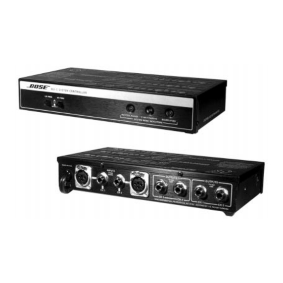
- Page 1 ® 802C System Controller Original and SMD Version Units with serial numbers beginning with 100000 are the original 802C's. Units with serial numbers beginning with 200000 are the new SMD 802C's. Service Manual © 1997 Bose Corporation Part Number 129292 REV 03...
-
Page 2: Table Of Contents
Technical Description ........................6 Disassembly/Assembly Procedures ....................7 Figure 1. Locking Tab Screw Location ..................... 7 Figure 2. Original 802C PCB Exploded View ................... 8 Figure 3. SMD 802C PCB Exploded View ..................8 Test Procedures .......................... 9-10 Part List Notes ..........................11 Main Part List .......................... -
Page 3: Safety Information
BOSE ® CORPORATION WHICH IS BEING FURNISHED ONLY FOR THE PURPOSE OF SERVICING THE IDENTIFIED BOSE PRODUCT BY AN AUTHORIZED BOSE SERVICE CENTER OR OWNER OF THE BOSE PRODUCT, AND SHALL NOT BE REPRODUCED OR USED FOR ANY OTHER PURPOSE. -
Page 4: Electrostatic Discharge Sensitive (Esds) Device Handling
ELECTROSTATIC DISCHARGE SENSITIVE (ESDS) DEVICE HANDLING This unit contains ESDS devices. We recommend the following precautions when repairing, replacing or transporting ESDS devices: • Perform work at an electrically grounded work station. • Wear wrist straps that connect to the station or heel straps that connect to conductive floor mats. -
Page 5: Specifications
SPECIFICATIONS Input Connections: One (1) balanced female XLR connector (per channel) One (1) unbalanced 1/4" phone jack Output Connections: Two (2) 1/4" phone jacks per channel (per channel) (outputs used depend upon mode selected) Input Impedance: Balanced input, 4kΩ Unbalanced input, 42kΩ Electronic Crossover Frequency: 180Hz (bi-amplified mode only) -
Page 6: Technical Description
"piggy-back" PCB and place all electronics on one single printed circuit board. This manual will identify the different procedures, PCB layouts, and components where necessary. There is no difference in the operation or function between the original 802C and the 802C SMD units. -
Page 7: Disassembly/Assembly Procedures
XLR jacks. 3. 302EQ ("piggy-back") PCB Removal 6. Main PCB Replacement Note: The original 802C has two PCB's. The following procedure will discuss the 6.1 Carefully slide the PCB into the chas- removal of the "piggy-back" PCB. -
Page 8: Figure 2. Original 802C Pcb Exploded View
Figure 2. Original 802C PCB Exploded View Figure 3. SMD 802C PCB Exploded View... -
Page 9: Test Procedures
(see top cover diagram on page 17), Frequency Output Tolerance ± 1.8dB equalization curves and output vary. You 55Hz +9.3dB must test all modes of the 802C to assure 750Hz (reference) proper operation. ± 2.0dB 15kHz +6.9dB 1.2 Perform the test below to verify that the 3. -
Page 10: Test Procedures
TEST PROCEDURES 4.4 Apply a 100Hz, 500mVrms signal to 6. Noise Test the input of the 802C. 6.1 All noise measurements are ANSI 4.5 Reference a dB meter to the 302 AMP A-weighted true rms, with the inputs output jacks (while in the Bi-Amp mode). -
Page 11: Part List Notes
PART LIST NOTES 1. This part is not normally available from Customer Service. Approval from the Field Service Manager is required before ordering. 2. The individual parts located on the PCB are listed in the Electrical Part List. This part is critical for safety purposes. Failure to use a substitute replacement with the same safety characteristics as the recommended replacement part might create shock, fire and or other hazards. -
Page 12: Main Part List
MAIN PART LIST (See Figure 4) Item Description Part Note Number Number COVER 135040 CHASSIS 133230 FEET 103593 SCREW, SHEET METAL, 103118-04 4-40 x .25L CONNECTOR, XLR 121810 NUT, KNURLED 121890 STRAIN RELIEF BUSHING 106346 LINE CORD, 100/120V 111672 LINE CORD, 220V 113608 123487 BRACKET, LED... -
Page 13: Figure 4. Main Parts Exploded View
Figure 4. Main Parts Exploded View... -
Page 14: Electrical Part List
ELECTRICAL PART LIST Resistors Reference Description Part Note Designator Number R1, 2 2.7kΩ, 1/4 Watt, 5% 117704- 1212725 R3, 4 3.3kΩ, 1/4 Watt, 5% 117704- 1213325 R5-7, 11, 15, 118, 218 160kΩ, 1/4 Watt, 5% 117704- 1211645 R8, 9, 12, 13, 16, 17, 101, 210, 104, 330kΩ, 1/4 Watt, 5% 117704- 1213345... - Page 15 ELECTRICAL PART LIST Resistors (continued) Reference Description Part Note Designator Number R144, 244 56kΩ, 1/4 Watt, 2% 117704- 1215632 R148, 248 4.12kΩ, 1/4 Watt, 1% 119976- 2214121 R149, 249 23.7kΩ, 1/4 Watt, 1% 119976- 2212372 R150, 250 30.9kΩ, 1/4 Watt, 1% 119976- 2213092 R160, 260...
- Page 16 ELECTRICAL PART LIST Capacitors Reference Description Part Note Designator Number .0047uF, 220V 120993 .0047uF, 1.4KV, 100/120V 103447 C2, 3 .015uF, FILM 118091-153 .01uF, CERAMIC DISC 119696-103 C5, 6 470uF, ELECTROLYTIC 110704 C7-10 1uF, ELECTROLYTIC 119942-1R0 C11-19, 22 .1uF, CERAMIC DISC 117502 C101, 117, 125, 201, 217, 225 22uF, ELECTROLYTIC...
-
Page 17: Electrical Part List
ELECTRICAL PART LIST Diodes Reference Description Part Note Designator Number D1-5 ZENER, 18V, 1W, IN4746A 116995-4746A D1, 101, 104, 201-204 1N4148, DIODE 121501 BRIDGE RECTIFIER 112027 Transistors Reference Description Part Note Designator Number Q1, 4, 5 TRANSISTOR NPN 117921 Q2, 3, 6 TRANSISTOR PNP 119168 Integrated Circuits... -
Page 18: Voltage Conversion Instructions
VOLTAGE CONVERSION INSTRUCTIONS Voltage Conversions are to be performed on Military units. However it is possible to convert a 110 Volt unit (by replacing the transformer) and a 220 Volt European unit. 1. 220 Volt to 110 Volt Conversion 2. 110 Volt to 220 Volt Conversion Note: Conversions must be performed 2.1 Perform disassembly procedure 3, with the line cord disconnected from any... -
Page 19: Figure 6. Top Cover Connection Diagram
Figure 6. Top Cover Connection Diagram... - Page 20 SPECIFICATIONS AND FEATURES SUBJECT TO CHANGE WITHOUT NOTICE ® ® Bose Corporation The Mountain Framingham Massachusetts USA 01701 P/N 129292 REV. 03 10/97 FOR TECHNICAL ASSISTANCE OR PART ORDERS, CALL 1-800-367-4008...