Table of Contents
Advertisement
Quick Links
Download this manual
See also:
Owner's Manual
Advertisement
Table of Contents

Related Manuals for Audiovox GMR-GPS


Summary of Contents for Audiovox GMR-GPS
- Page 1 General Mobile Radio Service (GMRS) Transceiver With Global Positioning System (GPS) Capability Model GMR-GPS Owner’s Manual Customer Service 1-800-290-6650 Released 10/19/01...
-
Page 2: Table Of Contents
Using Rechargeable Batteries or Vehicle Cigarette Lighter Battery Eliminator ... Operational Modes ... 10 GMR-GPS Gateway Page Access to the Menu Pages ... 11 Scrolling Through the Menu Pages ... 12 GMR-GPS Operational Menu Flow Diagrams (Figures 1-5) ... 13 Setting Up the GMR-GPS Unit ... -
Page 3: Warning
WARNING: • The GMR-GPS should be used as an aid in navigation. The unit is not intended to replace basic navigational procedures and common sense. • Because of errors inherent in the nature of the GPS system, the unit will not guide you to an exact position or the precise indicated coordinates. -
Page 4: General Features
GPS receivers. As with all other GPS units available to the public, the GMR-GPS makes use of the C/A signals to establish position and altitude. The accuracy of a displayed position varies with a number of factors including time. -
Page 5: The Gps Receiver
THE GPS RECEIVER A GPS receiver such as the GMR-GPS uses the C/A signals from the satellites to determine its position on earth. Signals from three satellites are needed to provide an unambiguous position fix, with reliable altitude indications requiring a fourth. In most circumstances, a GPS receiver will be able to receive signals from more than four satellites and can decide which it will use to give the best position. -
Page 6: Getting To Know Your Gmr-Gps Unit
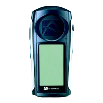
GETTING TO KNOW YOUR GMR-GPS UNIT 1. Push-to-Talk Button (PTT) Button: Used during GMRS radio operation when transmitting voice signals and call tones. 2. Global Positioning System Antenna: Provides reception of GPS satellite signals to determine location. The unit should be held upright to maximize received satellite information. -
Page 7: Operational Status Icon Definition
Page Button (PAGE): Scrolls sequentially through menu pages in the forward direction, and also provides access to a shortcut display for easy acquisition of main GPS displays. Battery Compartment Cover: Allows access to four AA batteries when removed. DC6V Jack: It accepts a DC-to-DC vehicle cigarette lighter battery eliminator adapter. Battery Charging Contacts: Provide in-unit charging of batteries when unit is placed in charging stand. -
Page 8: Accessories
This will ensure optimum performance for the GMR-GPS. Use of the Audiovox charger with other brands of batteries is not recommended, as battery charging times will vary. Refer to the manufacturer’s instructions for charging other brands of batteries. -
Page 9: Using Rechargeable Batteries Or Vehicle Cigarette Lighter Battery Eliminator
Using Rechargeable Batteries or Vehicle Cigarette Lighter Battery Elimina- tor: When rechargeable batteries are installed in the GMR-GPS unit, they can be recharged by placing the unit on the optional charging stand, Part Number GMRGPS-SC. CAUTION: The optional charging stand is intended for use only with Audiovox-approved rechargeable (NiMH) batteries (P/N GMRGPS-BT). -
Page 10: Operational Modes
OPERATIONAL MODES The GMR-GPS is capable of three modes of operation; namely, RADIO ONLY, GPS ONLY or GPS + RADIO. The desired mode can be selected using the Setup menu once the unit is turned on and in the standby mode. -
Page 11: Gmr-Gps Gateway Page Access To The Menu Pages
PRESS/HOLD PAGE MAP PAGE PRESS ENTER PRESS/HOLD PAGE PRESS ENTER MENU PAGE PRESS/HOLD PAGE GMR-GPS Gateway Page Access to the Menu Pages PRESS ENTER PRESS/HOLD PAGE PRESS ENTER RESS/HOLD PAGE PRESS ENTER GATEWAY PAGE PRESS AND HOLD PAGE TO AC- CESS GATEWAY DISPLAY FROM ANY PRIMARY DISPLAY PAGE;... -
Page 12: Scrolling Through The Menu Pages
Scrolling Through the Menu Pages: 1. With the unit in the GPS ONLY or GPS + RADIO standby mode, pressing the PAGE button will permit scrolling through the primary radio/GPS menu pages. a. Navigation Page b. Map Page c. Pointer Page d. -
Page 13: Gmr-Gps Operational Menu Flow Diagrams (Figures 1-5)
GMR-GPS Operational Menu Flow Diagram, Figure 1... - Page 14 GMR-GPS Operational Menu Flow Diagram, Figure 2...
- Page 15 GMR-GPS Operational Menu Flow Diagram, Figure 3...
- Page 16 RADIO SETUP ONLY MODE FROM FIGURE 1 PRESS PAGE GMR-GPS Operational Menu Flow Diagram , Figure 4 PRESS PAGE PRESS ENTER PRESS PRESS PAGE ENTER PRESS PAGE RADIO ONLY STANDBY PAGE SET DUAL CHANNEL (1-15) OFF/1-9 MELODIES VOX DELAY OFF/ 1-4 SEC...
- Page 17 GMR-GPS Operational Menu Flow Diagram, Figure 5...
-
Page 18: Setting Up The Gmr-Gps Unit
SETTING UP THE GMR-GPS UNIT After the GMR-GPS unit is turned on, it should be set up and/or tailored for operation according to user specific needs. To accomplish this, the basic SETUP mode must be accessed and the required information needs to be entered. Access the SETUP mode as follows: 1. -
Page 19: Adjusting The Volume
(1) Press Enter; an alphanumeric window appears with a highlighted number/letter corresponding to the character presently being used. (2) Using the Up/Down wheel key, highlight the first ID character desired and press Enter. The first character changes and the cursor moves to the second character position. -
Page 20: Setting Up The Gps Feature
2. Move the wheel key in the up or down position to increase or decrease the volume setting. The volume bar graph will increase or decrease in steps, accordingly, to a maximum of 16 or a minimum of 1. SETTING UP THE GPS FEATURE Now that the basic setup procedures have been performed, you must now perform the setup proce- dure for the GPS feature. -
Page 21: Paging Through Gps Functions
PAGING THROUGH GPS FUNCTIONS INITIALIZING THE GLOBAL POSITIONING SYSTEM MODE Before using the GPS mode of your GMR-GPS unit for the first time, the GPS receiver needs to automatically determine its location. To initialize the GPS receiver, proceed as follows: WATCHING SATELLITE ACQUISITION ON THE GPS STANDBY/STATUS PAGES Your GMR-GPS unit operates on positional data acquired from NAVSTAR satellites. -
Page 22: Gps + Radio Standby Page
GPS + Radio Standby Page The GPS + RADIO Standby page automatically appears as the default page if the unit is being turned on for the first time, or if it is selected as the operational mode using the SETUP page. In addition to depicting satellite acquisition (SEARCHING/NAVIGATION), this page also displays the following information: 1. -
Page 23: Radio Only Standby Page
GPS Only Standby Page Radio Only Standby Page The RADIO ONLY Standby page (shown above) can be selected from the SETUP page using the MODE function as previously explained. Unlike the other two modes which include the GPS feature, this standby page depicts a radio only display with the following information: 1. -
Page 24: Hot Key Menu Access
PRESS PAGE PRESS PAGE Hot Key Menu Access A HOT KEY menu is accessible from either the GPS + RADIO or RADIO ONLY standby page; this page appears when the Enter switch is pressed, and provides you with quick access to the basic radio functions. -
Page 25: The Navigation Page
The NAVIGATION page presents a summary of the important parameters entered into, or com- puted by your GMR-GPS unit. This page can be accessed from the GPS + RADIO or GPS ONLY standby pages, or it can be accessed from the Gateway menu which is available from any of the pages when operating in the one of the GPS modes. -
Page 26: The Mark Waypoint Page
MAP VIEW (on the map page) of the waypoint in question. If the send option is used, your present location (coordinates) is transmitted to another GMR-GPS unit so it knows where you are. The following display appears when the Mark (M) button is momentarily pressed:... -
Page 27: The Map Page
5. SEND - To transmit the current coordinates, together with user (your) ID, to a remote user GMR-GPS unit tuned to the same channel (and CTCSS sub-code), simply highlight the SEND field and press the Enter switch. At the receiving unit, a loud special tone will be heard signifying receipt of the coordinate information. -
Page 28: The Pointer Page
CURRENT LONGITUDE CURRENT LATITUDE ALTITUDE CURRENT TIME HEADING TRAVEL SPEED TRIP TIME ODO (ODOMETER) BEARING DISTANCE TRUE NORTH POINTER PERCENT MEMORY USED BAR a. AHEAD/NORTHWARD? - When this item is highlighted, press Enter to orient the top of the map display with respect to waypoints or targets ahead of your intended track, or with respect to True North. - Page 29 2. Whether or not the satellite information is sufficient for the unit to provide accurate positional information (SEARCHING or NAVIGATION). The indication provides the level of accuracy of the position based upon the number of satellite signals being received. 3. An information bar at the bottom of the display permits viewing the following parameters when the Up/Down wheel key is used: a.
-
Page 30: The Gps Menu Page
4. When the Enter switch is pressed, a sub-menu appears in the center of this screen, and provides several options related to your trip; these options can be highlighted using the Up/Down wheel key; then press Enter to change the highlighted data: a. - Page 31 a. The WAYPOINTS display presents an alphanumeric listing of the waypoints you have marked along your trip. In addition, they appear automatically in numeric order (unless you enter a waypoint ID preceding the waypoint number) as they are marked and entered sequentially.
- Page 32 Using and Editing the Waypoints During Your Trip 2. ROUTES - Routes consist of at least two or more waypoints that define a path to a destination. This feature guides you from the first waypoint in the route to each successive waypoint until you complete your trip.
- Page 33 Using and Editing the Routes on Your Trip d. This process can be repeated until all the desired waypoints are incorporated into the TRIP route (01) page. e. Whenever a change is made to an item in the route, a MESSAGE display appears when the PAGE button is pressed to return to the ROUTES display.
- Page 34 Using and Editing the Tracks on Your Trip a. TRACKBACK - With the TRACKS field of the GPS MENU highlighted, press Enter; The TRACKS menu appears with the first track position highlighted. Using the Up/ Down wheel key, highlight the desired track and press Enter. TRACK LOG LOADING appears momentarily and the memory bar at the top of the screen indicates the percent of track data points remaining to be loaded.
- Page 35 GMR-GPS units or, when the Mark (M) button is pressed, your coordinates are transmitted to another GMR-GPS unit to provide a fix on your location. To access received coordinates, press the Up/Down wheel key to highlight the GP LOCATOR field on the GPS MENU page;...
-
Page 36: Taking A Trial Run
LET’S BEGIN To begin with, let’s mark your current location as a waypoint. NOTE: The GMR-GPS unit must be in the NAVIGATION mode (satellites acquired) before you begin your trial run. MARK YOUR WAYPOINT Mark your current position as follows: 1. - Page 37 Highlight the SAVE field and press Enter; the MARK screen reappears. Your new starting symbol and waypoint name are now stored in GMR-GPS memory. h. Press PAGE to return to the GPS MENU page. 6. To Change the Waypoint Location: a.
-
Page 38: Lets Take A Short Trip
To save the changes, highlight SAVE and press Enter; the new Latitude and Longitude specifying your location are stored in memory; to cancel the changes, highlight CANCEL and press Enter. LETS TAKE A SHORT TRIP Now that the unit knows where you are, press the PAGE button to access the Map page, and let’s take a short trip. -
Page 39: Locating Another Gmr-Gps User
LOCATING ANOTHER GMR-GPS USER During an excursion with another GMR-GPS user, it is possible to locate this user’s position provided he/she transmits the position, thereby giving you the coordinates of the remote GMRS-GPS unit. To transmit and receive the coordinates, both GMR-GPS units must set to same radio channel number and CTCSS subcode number. -
Page 40: Gmr-Gps Radio Operation
GMR-GPS RADIO OPERATION In addition to its Global Positioning System (GPS) features, the GMR-GPS unit also provides General Mobile Radio Service (GMRS) capability as a hand-held radio transceiver. As a GMRS transceiver, the unit permits radio operation with features such as Coded Tone Controlled Squelch System (CTCSS), Voice-Operated Transmission (VOX), Dual Channel Scan and Key Lock capability. -
Page 41: Accessing The Radio Setup Parameters
GMRS operation. ACCESSING THE RADIO SETUP FUNCTIONS Prior to using the radio feature of your GMR-GPS unit, the operating parameters must be set up to establish basic operating modes, such as channel scan, VOX operation, Roger Beep tone on/off, and call melody selection. -
Page 42: Explanation And Use Of Radio Setup Functions
EXPLANATION AND USE OF RADIO SETUP FUNCTIONS The radio setup functions, as noted earlier, etc. Dual Channel Selection In the RADIO setup menu, the first item listed is DUAL CH. - Highlight this line using the Up/Down wheel key and press Enter. - A menu appears, listing 10 channels (01-10). -
Page 43: Accessing The Hot Key Radio Operating Modes
Accessing the Hot Key Radio Operating Modes Once the basic radio parameters have be set up, the GMRS functions can be activated as desired during radio operation; these functions include selection of the primary operating channel (1-15) and CTCSS sub-code (1-38), priority channel scan mode activation, VOX mode activation, and key lock activation. -
Page 44: Explanation Of Hot Key Menu Use
The radio function of the GMR-GPS has 15 channels (frequencies 1-15) as indicated on the HOT Key page to the right of the CH item, and also on the standby page. Channels 1 through 7 are the same frequency as FRS channels 1 through 7. - Page 45 To enable the channel scan mode: - From GPS + RADIO or RADIO ONLY standby mode, press Enter to access the HOT KEY display; use the Up/Down wheel key switch to highlight the scan mode to the right of the SCAN item.
-
Page 46: Notes For Good Communication
NOTES FOR GOOD COMMUNICATION 1 . The 15 channels of the GMR-GPS are shared on a ‘take turns’ basis. This means other groups may be talking on any of the channels. A common code of ethics/courtesy is to switch to another vacant channel and not to attempt to talk over someone who is already using the channel you first selected. -
Page 47: Troubleshooting
Troubleshooting... -
Page 48: Technical Specifications
Technical Specifications: General Frequency Range: 15 GMRS Channels (7 Shared FRS) Channel Spacing Privacy Codes Dimensions (W x H x D) (Without Antenna) Power Supply Power Source Operating Time (Transmit: Receive: Standby) Receiver Useable Sensitivity Maximum Audio Output Power > 0.3 Watt maximum (8 Ohm ) Modulation Distortion Transmitter RF Output Power... -
Page 49: Main Channel Frequencies
This transceiver complies with FCC regulations for use in the United States of America. Use in other countries may be prohibited or restricted by local regulation. Please check with the local regulating agency before using this device outside the United States of America. Main Channel Frequencies: Channel Freq. -
Page 50: Continuous Tone Coded Squelch System Tone Frequencies (In Hz)
Continuous Tone Coded Squelch System Tone Frequencies (in Hz) CTCSS Freq. Hz 67.0 71.9 74.4 77.0 79.7 82.5 85.4 88.5 91.5 94.8 97.4 100.0 103.5 107.2 110.9 114.8 118.8 123.0 127.3 = No Tone CTCSS Freq. Hz 131.8 136.5 141.3 146.2 151.4 156.7... -
Page 51: Warranty
90 DAY LIMITED WARRANTY Applies to Audiovox Family Radio and General Mobile Service Products. AUDIOVOX CORPORATION (the Company) warrants to the original retail purchaser of this product that should this product or any part thereof, under normal use and conditions,... - Page 52 © 2001 Audiovox Electronics Corp., Hauppauge, NY 11788 Printed in Korea 128-6146...