
Related Manuals for Mira Gem 88


Summary of Contents for Mira Gem 88
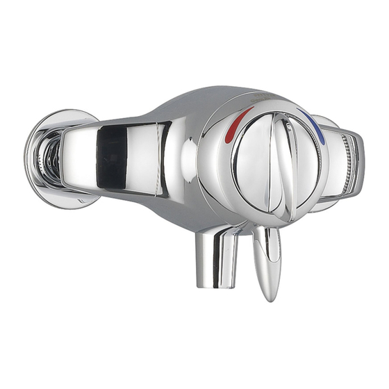
- Page 1 MIRA GEM 88 SHOWER CONTROL Installation & User Guide These instructions are to be left with the user...
-
Page 2: Table Of Contents
Installation Requirements ..............10 Typical suitable installations .............. 11 Installation ..................... 16 Mira Gem 88 - Surface Mounted Shower Control ........ 16 1. Rising and falling inlet supplies ............16 2. Rear entry inlet supplies..............19 Mira Gem 88 B - Built-in Shower Control ..........22 1. -
Page 3: Introduction
Chrome or white colour models are available. The Mira Gem 88 is designed to be fitted with the pipe centres set at a distance of 153 mm for rear supply connection and the pipes centre set at a distance of 151 mm for rising / falling pipes connection (See the installation template provided). -
Page 4: Important Safety Information
IMPORTANT SAFETY INFORMATION Warning! Products manufactured by us are safe and without risk provided they are installed, used and maintained in good working order in accordance with our instructions and recommendations. Caution! Read all of these instructions. Retain this guide for later use. Pass on this guide in the event of change of ownership of the installation site. -
Page 5: Pack Contents Checklist
PACK CONTENTS CHECKLIST Tick the appropriate boxes to familiarize yourself with the part names and to confirm that the parts are included. 1. Mira Gem 88 Surface Mounted Shower Control 2 x Pipe Concealing Plates 2 x Compression Nuts **2 x Olives... - Page 6 2. Mira Gem 88 Built-in shower control 1 x Mira Gem 88 B Shower Control ** 2 x Fixing Screw ** 2 x Flow regulator With Building-in Shroud ** 1 x 2.5 mm A/F ** 2 x Wall Plug Hexagonal Wrench...
-
Page 7: Dimensions
DIMENSIONS 1. Mira Gem 88 Surface Mounted Shower Control 149 - 154 2. Mira Gem 88 Built-in shower control 50 - 68 Note! NOT TO SCALE - All dimensions are nominal and in millimetres... -
Page 8: Specifications
SPECIFICATIONS 1. Pressure Range Mira Gem 88 1.1 Minimum maintained pressure 0.1 bar (1.0 metre head) when used with Mira shower fittings. 1.2 Maximum maintained pressure 5 bar. 1.3 Maximum static pressure 10 bar. Mira Gem 88 B 1.4 Minimum maintained pressure 0.1 bar. -
Page 9: Flow Rates
4. Flow Rates Mira Gem 88 with LC Response Shower Fittings Sooth Start Force Economy Mira Gem 88 with HC Response Shower Fittings Sooth Force Start Economy... -
Page 10: Installation Requirements
Do not install the Gem 88 to an instantaneous water heater or combination boiler system. The Mira Gem 88 is designed to be fitted with the pipe centres set at a distance of 153 mm for rear supply connection and the pipe centres set at a distance of 151 mm for rising / falling pipes connection (See the installation template provided). -
Page 11: Typical Suitable Installations
Typical suitable installations Key to symbols Twin impeller inlet pump Float operated valve Stop or servicing valve Tempering valve Mini expansion vessel Shower control Non-return Valve Warning or overflow pipe Drop tight pressure reducing valve (PRV) Gravity fed showers - The shower control MUST be fed from a cold water storage cistern and hot water cylinder providing nominally equal pressures. - Page 12 Pumped showers (inlet pumps) - The shower control can be installed with an inlet pump (twin impeller). The pump MUST be located on the floor next to the hot water cylinder. The hot water cylinder/vent pipes must be arranged as shown to achieve air separation.
- Page 13 Unvented mains pressure showers - The shower can be installed with an unvented, stored hot water cylinder. Only a "competent person" as defined by the Building Regulations may fit this type of system. For packages with no cold water take off after the appliance reducing valve, it will be necessary to fit an additional drop tight pressure reducing valve when the mains pressure is over 5 bar.
- Page 14 Mains pressurised instantaneous hot water shower, heated from a thermal store - Packages of this type, fitted with a tempering valve can be used. A drop tight pressure reducing valve MUST be fitted if the supply pressures exceed 5 bar maintained. An expansion vessel MUST be fitted (and regularly maintained) if any form of backflow prevention device is fitted, e.g.
- Page 15 High pressure installations If water flow from the shower is too high or maintained pressure over 1 bar, the fitting of a flow regulator is recommended (as illustrated below). Exposed shower valves and BIV Nipple Outlet Fit the white 12 l/min flow regulator to the hose.
-
Page 16: Installation
(rising) Hose Retaining Ring or top (falling). 1.2 The Mira Gem 88 is supplied with inlet 25 mm Minimum connections hot left, cold right and bottom outlet as standard. - Page 17 1.6 Drill and suitably plug the two fixing Backplate holes. Secure the backplate to the wall by means of the screws provided. Screw 1.7 Install the hot and cold supply pipes. The distance between the pipe centres must be 151 mm. Wall Plug 1.8 Adjust the inlet elbow to accept falling V Groove...
- Page 18 Note! If this is not the case, refer to section: Reversed inlets. Turn flow lever fully clockwise to stop water flow. 1.14 This completes the installation of the Mira Gem 88 for connection to rising and falling inlet supplies. Temperature Knob Flow lever...
-
Page 19: Rear Entry Inlet Supplies
2. Rear entry inlet supplies 2.0 The Mira Gem 88 is supplied with inlet connections hot left, cold right and Hose Retaining Ring bottom outlet as standard. 25 mm Minimum 2.1 Decide on a suitable position for the shower control. The position of the... - Page 20 2.6 Loosen the backplate grub screw and using the 2.5 mm A/F hexagonal Supply Pipe Concealing Plate wrench provided, remove the backplate from the shower control body. Compression Nut 2.7 Drill and suitably plug the two fixing Olive holes. Secure the backplate to the wall by means of the screws provided.
- Page 21 Note! If this is not the case, refer to section: Reversed inlets. Turn the flow knob fully clockwise to stop the water flow. 2.15 This completes the installation of the Mira Gem 88 for connection to rear entry inlet supplies.
-
Page 22: Mira Gem 88 B - Built-In Shower Control
The shower control is not supplied with any interconnecting pipework or plumbing fittings. Inlet and outlet threads are 1/2" BSP female parallel. The Mira Gem 88 is supplied with inlet connections hot left, cold right and bottom outlet as standard. - Page 23 1.3 Drill and plug the fixing holes. Using the screws provided, if appropriate, fix the shower control and backplate assembly into the recess, making sure that the two retaining screw holes are Fixing at 45° as illustrated. (Make sure that Screw the shower control inlets are horizontal with the shower control...
- Page 24 1.9 Fit the concealing plate bracket Concealing Plate assembly over the valve and fix to the Bracket Assembly Plastic Clips wall with the two retaining screws (Take care not to damage the foam seal). 1.10 Fit the concealing plate over the valve. Make sure that the plastic clips are Retaining aligned centrally on the metal bracket...
- Page 25 Note! If this is not the case refer to section: 'Reversed inlets'. Turn flow knob fully clockwise to stop water flow. 1.18 This completes the installation of the Mira Gem 88 B into solid or dry-lined wall structures. Temperature Knob...
-
Page 26: Stud Partition Or Dry Partition Wall Structures
2. Stud partition or dry partition wall structures The support bracket (from Mira stocklist as an optional accessory) has been designed to allow the shower control to be installed into the front face of a stud partition wall and is recommended for this type of installation. However, installers may wish to consider other options such as fabricated rear supports using wooden noggins, however, these methods of fixing are beyond the scope of this guide. - Page 27 2.3 Fit the shower control to the support bracket with the screws, nuts and 4 mm washers supplied. Fix the support bracket and shower control in position using suitable fixing (not supplied). Note! The support bracket requires a clearance depth of 60 mm, with a wall thickness of 4 mm.
-
Page 28: Shower Cubicle Or Laminated Panel
3. Shower cubicle or laminated panel The support bracket (optional) is recommended to fit the shower control into a shower cubicle or laminated panel 2 - 20 mm thick. The dimension from the bracket to the finished wall surface is 50 - 68 mm. 2 to 20 mm 3.1 Cut a 108 mm diameter hole in the Finished... - Page 29 3.3 Fit the shower control and the Support Bracket backplate to the support bracket with Nuts the screws, the nuts and the washers supplied. Washers Retaining Screws Support Bracket 3.4 Secure the bracket to the wall with the screws provided. 3.5 Follow the shower control installation procedure as for Solid or dry-lined wall structures instructions 1.4 to 1.7...
-
Page 30: Refitting The Cavity Seal
REFITTING THE CAVITY SEAL Unscrew and remove the two cartridge retaining screws and remove the Seal cartridge from the body. Check that the seal on the base of the cartridge is clean and fitted. Cavity Seal Cut-out Screw Position Align the cut-outs on the cavity seal with the screw positions on the cartridge. - Page 31 Place the cavity seal and the cartridge assembly on a flat surface. Screw Position Screw Position Shroud Cut-Out Shroud Align the cut-outs on the shroud with the screw positions on the cartridge. Push down firmly on the shroud while lifting the edge of the cavity seal over the lip of the shroud.
-
Page 32: Reversed Inlets
REVERSED INLETS In the event that the temperature control is not functioning as described, anticlockwise HOT and clockwise COLD, then follow the instructions below. Make sure the temperature control is positioned with the levers pointing down, as illustrated. Temperature Knob Removal Unclip the temperature knob by hand to access the cartridge spindle. -
Page 33: Operation
OPERATION Warning! The temperature control can be turned from FULL HOT to FULL COLD. As such, turning the control to full hot will deliver water at the hot water storage temperature. Turn the flow control lever 1/4 of a full Flow turn anticlockwise to turn the water on or clockwise to turn the water off. -
Page 34: Maintenance
Fault diagnosis Read the section “Important Safety Information” first. Mira products are fully performance tested after assembly. In the unlikely event that you experience problems with your shower the following procedure will enable you to undertake basic fault finding before contacting Kohler Mira Limited for further assistance or spare parts as necessary. -
Page 35: General
You may, if you wish, choose to engage the services of a Mira Service Engineer or Agent, the terms of which are outlined on the back page of this guide. -
Page 36: Spare Parts
SPARE PARTS Mira 88 spare parts list 055.14 Backplate Assembly 090.95 Pipe Concealing Plate - chrome 458.01 Handle pack - chrome 458.02 Handle pack - white 458.04 Body trim pack - chrome - components identified 'A' 458.05 Body trim pack - white - components identified 'A' 458.06... - Page 37 Mira Gem 88 spare parts diagram 458.01 458.02 458.17 055.14 618.22 458.07 458.06 458.12 055.14 572.12 090.95 458.11 618.23 553.35 623.70 458.10 458.04 458.05...
- Page 38 Mira Gem 88 B spare parts list 052.11 Backplate Assembly 079.61 Building-in Shroud 458.01 Handle pack - chrome 458.02 Handle pack - white 458.08 Concealing plate assembly 458.09 Concealing plate assembly 458.10 Cartridge 458.12 Body 458.16 Concealing plate mounting kit - components identified 'D' 458.18...
- Page 39 Mira Gem 88 B spare parts diagram 618.23 517.12 458.12 458.15 458.18 458.10 052.11 458.01 458.08 458.02 458.09 079.61...
-
Page 40: Accessories
Support Bracket: Allows the shower control to be fitted into a shower cubicle, stud partition or dry partition wall. Available as optional accessory from your Mira stockist. DCV-H: An outlet double check valve, requiring a minimum inlet supply pressure of 0.5 bar, which has been designed to prevent the backflow or back-siphonage... -
Page 41: Notes
NOTES... - Page 42 NOTES...
- Page 43 NOTES...
-
Page 44: Customer Service
CUSTOMER SERVICE UKAS 1061361-W2-A © Kohler Mira Limited, April 2006... - Page 45 Pdf Supplied By http://www.plumbworld.co.uk/...