Table of Contents
Advertisement
Quick Links
Advertisement
Table of Contents

Related Manuals for Martin Audio BlacklineX SERIES


Summary of Contents for Martin Audio BlacklineX SERIES
- Page 1 BlacklineX User Guide...
- Page 2 BlacklineX USER GUIDE BlacklineX User Guide V1.0 ...
-
Page 3: Table Of Contents
BlacklineX USER GUIDE Content Introduction ...................................... 6 Unpacking ...................................... 6 BlacklineX Series overview ................................ 7 2‐way full‐range systems: ................................ 7 Direct radiating ported sub‐bass systems ............................ 7 2‐way passive full‐range systems .............................. 8 X8 ........................................ 8 X10 ........................................ 9 X12 ...................................... 10 X15 ... - Page 4 BlacklineX USER GUIDE System F – Stereo Subwoofers using the bi‐amp wiring facility .................... 28 Products that may be used with this wiring;‐ ......................... 28 DX0.5 ...................................... 29 Introduction .................................... 29 Features ...................................... 29 Rear Panel .................................... 29 1. Power .................................... 29 2. Power Lead Socket and Fuse .............................. 29 3. Main: Lift / Gnd ................................... 30 4. XLR Outputs .................................. 30 5. XLR Inputs ................................... 30 ...
- Page 5 BlacklineX USER GUIDE Editing ...................................... 36 Inputs A / B: .................................... 36 Gain ...................................... 36 Delay ....................................... 36 EQ Bypass .................................... 37 5‐Band EQ .................................... 37 Outputs 1‐6: .................................... 38 Name ...................................... 38 Source ..................................... 38 Polarity .................................... 38 Gain ...................................... 38 ...
- Page 6 BlacklineX USER GUIDE X115 ...................................... 60 X118 ...................................... 60 X210 ...................................... 61 Warranty ...................................... 62 BlacklineX User Guide V1.0 ...
-
Page 7: Introduction
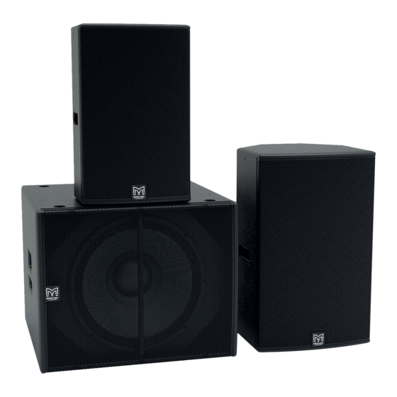
BlacklineX USER GUIDE Introduction Thank you for purchasing a Martin Audio BlacklineX Series system. Now, with BlacklineX, Martin Audio’s R&D team has engineered a classic suite of passive loudspeakers for the modern era. Delivering the signature sound of warmth, nuance and clarity but with improved overall performance at a price point not previously possible, BlacklineX is a clean, smart design with no compromise between the needs of installation and portability. Applications range from portable sound reinforcement and stage monitoring for live bands, DJ’s and corporate events, to installations in nightclubs, bars, commercial spaces and HoW. Comprising four two‐way systems — from the ultra‐compact X8 to the powerful X15 — and three subwoofers, including an unobtrusive low‐profile model, the multi‐purpose BlacklineX Series raises the performance of loudspeaker systems in its class to ... -
Page 8: Blacklinex Series Overview
BlacklineX USER GUIDE BlacklineX Series overview The BlacklineX Series is made up of… 2‐way full‐range systems: X8 (8”+ 1”) X10 (10”+ 1”) X12 (12”+ 1”) X15 (15”+ 1”) Direct radiating ported sub‐bass systems X115 (single 15”, ported) user‐selectable 120Hz low‐pass filter X118 (single 18”, ported) user‐selectable 120Hz low‐pass filter X210 (2 x 10”, ported) user‐selectable 120Hz low‐pass filter BlacklineX User Guide V1.0 ... -
Page 9: 2-Way Passive Full-Range Systems
BlacklineX USER GUIDE 2‐way passive full‐range systems X8 The X8 is an ultra‐compact passive two‐way system featuring an 8” (200mm)/2”(50mm) voice coil LF driver and a 1” (25mm) HF driver mounted on a 90° x 50° horn which can be easily rotated for horizontal or vertical orientation. It's very small size gives no indication of its high output capability. As a stand‐alone loudspeaker, it has a multitude of professional applications— from distributed sound reinforcement, HoW and AV events to front‐fill/infill and use as a micro stage monitor. Complemented by a BlacklineX subwoofer, it is the ideal, simple‐ to‐use system for portable applications and installations which call for an unobtrusive system that can deliver pristine sound over short and medium throw distances. The X8 is constructed from birch/poplar plywood and fitted with a screw‐free steel grille, M8 inserts for a wall bracket and eyebolt ... -
Page 10: X10
BlacklineX USER GUIDE X10 The X10 is a high performance yet very compact two‐way passive loudspeaker system which utilises a 10” (250mm)/2.5” (63mm) voice coil LF driver and a 1” (25mm) exit HF compression driver with a 1.4” (35mm) polyimide diaphragm. The rotatable 90° x 50° HF horn has equal horizontal and vertical mouth dimensions for directivity control in both planes. With a maximum SPL of 124dB @ 1m, it is uniquely placed to meet the foreground requirements of music bars and clubs that require upfront sound levels from a very compact enclosure. Use with a BlacklineX Series subwoofer will enable the X10 to operate as small dancefloor or sound reinforcement system that is remarkably powerful for its size, as well as being extremely portable. The X10 is constructed from birch/poplar plywood and fitted with a screw‐free steel grille, M8 inserts for a wall bracket and eyebolt suspension, plus a pole‐mount socket. The X10 may be used with or without a system controller. For demanding applications, Martin Audio recommends a DX0.5 system ... -
Page 11: X12
BlacklineX USER GUIDE X12 The X12 fulfils the requirement for a compact system that can deliver high sound levels — either as a stand‐alone system or supplemented by a BlacklineX subwoofer. Featuring a 12” (300mm) LF driver unit and a 1” (25mm) exit compression driver on a rotatable horn, its 80° x 50° dispersion pattern is ideal for medium throw applications. The LF driver has a 2.5” (65mm) voice coil and a high BL motor, while the HF compression driver utilises a 1.75” (44mm) polyimide diaphragm for extended high frequency response. The X12’s enclosure is constructed from birch/poplar plywood and coated in black textured paint. For easy removal, its steel grille is a spring‐fit into the sides of the enclosure. It is fitted with M8 inserts for a wall bracket and eyebolt suspension, plus a pole‐mount socket with a removable bung that maintains clean lines when the X12 is used in install applications. The X12 may be used with or without a system controller. For demanding applications, Martin Audio recommends a DX0.5 system controller configured to perform EQ and limiter functions. The DX0.5 may also be used to configure systems for additional sub‐ bass cabinets – e.g. X12 + X115 or X118 BlacklineX User Guide V1.0 ... -
Page 12: X15
BlacklineX USER GUIDE X15 The X15 is a very high‐power, passive two‐way system designed for professional portable applications and installations that demand the ultimate in sonic performance from a single enclosure. With an accurately‐defined 80° x 50° coverage pattern, it combines very high output capability with exceptional sonic performance and impact. It features a powerful 15” (380mm)/3” (75mm) voice coil LF drive unit, and a 1” (25mm) exit HF compression driver with a 1.75” (44mm) polyimide diaphragm for extended high frequency response. Its protective steel grille is a spring‐fit into the sides of the enclosure for easy access to rotate the HF horn. The symmetrical, multi‐angle enclosure is manufactured from birch/poplar ply and coated in textured black paint. It is fitted with M8 inserts for a wall bracket and eyebolt suspension, plus a pole‐mount socket. The X15 may be used with or without a system controller. For demanding applications, Martin Audio recommends a DX0.5 system controller configured to perform EQ and limiter functions. The DX0.5 may also be used to configure systems for additional sub‐ bass cabinets – e.g. X15 + X118 ... -
Page 13: Sub-Bass Systems
BlacklineX USER GUIDE Sub‐bass systems X115 The X115 is a very compact subwoofer designed to augment the low frequency performance of BlacklineX Series full‐range systems. It comprises a long excursion 15” (380mm)/3” (75mm) voice coil driver in a bass reflex enclosure and can be used singly, stacked or flown via integral M10 inserts. Four large ports contribute to a reduction in air noise at high output levels. The enclosure is constructed from birch/poplar ply with a textured paint finish and the driver is protected by an impact‐resistant perforated steel grille which is pre‐curved to resist damage. The X115 has a 35mm pole‐mount fitting in the top surface that can be used to pole mount an X8, X10, or X12 above the enclosure, and two side handles for easy handling. The S115 is designed for use in a two way active bi‐amp system. A DX0.5 system controller is the idea system controller to provide the active crossover function and enhanced control facilities. ... -
Page 14: X118
BlacklineX USER GUIDE X118 The X118 is a compact, high performance subwoofer for use with BlacklineX Series full‐range loudspeakers. It extends the low frequency operating range of the combined system to 42Hz and provides exceptional low frequency impact. It can be used singly, stacked or flown via integral M10 insets and features a long‐excursion 18” (460mm)/3” (75 mm) voice coil driver in a compact reflex enclosure. Its four reflex ports have a large frontal area to reduce turbulent air noise at very high levels. The X118 enclosure is constructed from birch/poplar ply and finished in textured black paint. A perforated steel grille protects the driver, and the enclosure has a 35mm pole‐mount fitting in the top surface and two side handles. The S118 is designed for use in a two way active bi‐amp system. A DX0.5 system controller is the idea system controller to provide the active crossover function and enhanced control facilities. BlacklineX User Guide V1.0 ... -
Page 15: X210
BlacklineX USER GUIDE X210 The X210 is a slimline dual‐driver subwoofer designed for situations that call for a visually unobtrusive enclosure. It can be used singly, stacked or flown via integral M10 inserts and its ultra‐compact size makes it ideal for applications where space is limited. It features dual 10” (250mm)/2” (50mm) voice coil drivers and generously sized low frequency ports for reduced air noise. The enclosure is constructed from birch/poplar ply with a textured paint finish and the drivers are protected by an impact‐resistant perforated steel grille. It has twin ergonomic handles at the rear of the enclosure for easy handling. The S210 is designed for use in a two way active bi‐amp system. A DX0.5 system controller is the idea system controller to provide the active crossover function and enhanced control facilities. BlacklineX User Guide V1.0 ... -
Page 16: Accessories
BlacklineX USER GUIDE Accessories A comprehensive range of accessories is available for the BlacklineX range for both portable and installation use. Wall Brackets The BlacklineX range shares the mounting configuration of the CDD installation range so the same wall brackets can be employed. These are a two part bracket enabling the wall section to be fitted at first fix stage when cables are run. The cabinet half can be fitted to the speaker in advance of arriving at site so that final installation is just a case of joining the two halves of the bracket and adjusting the position for the coverage required, and connecting the cable. The brackets for each model are as follows;‐ Blackline X8 WB6/8B Blackline X10 WB10/12B Blackline X12 WB10/12B Blackline X15 WB10/12B BlacklineX User Guide V1.0 ... -
Page 17: Eye Bolts
BlacklineX USER GUIDE Eye Bolts All Blackline X Series speakers have threaded inserts available for flown applications in fixed installations. All full range cabinets have M8 inserts, all sub woofers have M10 inserts. The inserts can be used for fitting bespoke flying hardware or for flying using Eye Bolts. These must be forged steel shouldered types certified with a safe working load in excess of the cabinet weight. Do NOT be tempted to use cheap formed steel types commonly available from DIY stores as they are unsafe for flying heavy speaker cabinets. Correctly rated shouldered eye bolts are available from Martin Audio as an optional accessory, part numbers are as follows;‐ M8 (Blackline X8, 10, 12, 15) HTK00003 M10 (Blackline X210, 115, 118) HTK00004 BlacklineX User Guide V1.0 ... -
Page 18: Pole Mount
BlacklineX USER GUIDE Pole Mount BlacklineX Series speakers have integral pole mount "top hat" fittings. These are fitted to the base of all full range speakers; X8, 10, 12 and 15, and on the top of the Blackline X115 and 118. The fittings all use the standard 35mm diameter so they can be used with any regular speaker stand or accessory. The fitting in the subs allows use of a mounting pole to elevate one of the full range cabinets on top of the sub without the need for a bully and unsightly tripod stands. Distance poles are also widely available but Martin Audio make a pole specifically for use with the Blackline range. The part number is an HTKCT04. This will support any of the full range cabinets at the optimum height above either an X115 or X118. BlacklineX User Guide V1.0 ... -
Page 19: Safety First
BlacklineX USER GUIDE Safety first It is important that loudspeaker systems are used in a safe manner. Please take some time to review the following points concerning safe use of Blackline Series loudspeakers. Professional loudspeakers are capable of producing extremely high sound levels and should be used with care. Hearing loss is cumulative and can result from levels above 90dB if people are exposed for a long period. Never stand close to loudspeakers driven at high level. Pole or stand mounting BlacklineX full‐range loudspeakers incorporate pole mounting (“top hat”) sockets so that they may be pole or stand mounted. When using poles or stands, the following precautions are advised: Ensure that the stand will support the weight of the speaker by checking the stand manufacturers rating. (See the ... -
Page 20: Amplification
Use a DX0.5 or high quality system processor Use the published Parameters for the BlacklineX range Use an amplifier with a gain of 32dB (X40) Always run front panel gain controls full up Avoid amplifiers that only quote a sensitivity rating; "xxdB for maximum output" (i.e. no published gain setting) Recommended Amplifiers Model AES Power Peak Power Ideal amplifier rating Minimum rating Martin Audio amplifiers Rating Rating 4Ω 8Ω 4Ω 8Ω X8 200W 800W 1,600W 800W 800W 400W MA3.0, MA2.8Q X10 250W ... -
Page 21: Connections
BlacklineX USER GUIDE Connections There is a notable difference between the connections available of the Full Range systems, the X8, 10, 12, 15 plus the X210 subwoofer, and the X115 and X118 subs. The full range speakers have a connector panel with two Neutrik Speakon connectors wired in parallel with each other. The second connector allows use of a short link lead to power another, parallel BlacklineX loudspeaker. The connectors are wired as follows: X8, X10, X12, X15, X210 Note that although connections 2+/‐ are not used within the cabinets, they are still wired in parallel between the two NL4 connectors. Sub‐Woofer Connections The X210 has two paralleled NL4 Speakons however the X115 and X118 subwoofers feature an additional NL4 connector which ... - Page 22 BlacklineX USER GUIDE This diagram shows how the connectors are wired internally in the sub cabinets;‐ This shows how a bi‐amped system would be wired (single channel only shown for clarity);‐ BlacklineX User Guide V1.0 ...
- Page 23 BlacklineX USER GUIDE A Dx0.5 is used to provide the crossover function, output 1 is connected to channel A on an MA9.6K amplifier to drive the X118, channel 3 is connected to channel A on an MA3.0 to drive the X12s. The outputs from the amplifiers are combined into a single 4‐core cable with the MA9.6K feeding pins 1+/‐ and the MA3.0 feeding pins 2+/‐ (note that at the amplifier connection both Speakon connectors have connections made to pins 1+/‐). The 4‐core cable is connected to the Input on the X118, Link‐A is available to connect to a second sub for shows requiring very high levels of sub frequency. The Link‐B output uses a standard Speakon NL4 to connect the X118 up to the X12 ensuring that the X12 gets its signal from the MA3.0 amplifier. The diagram shows a custom cable which splits the 4‐core cable at the amplifier end to route the two feeds into the single cable, this could however be achieved but using a patch panel with NL4 connectors which have independent connections from both amplifiers going to pints 1+/‐ and 2+/‐ thus enabling a standard 4‐core Speakon cable to be used. This also makes it very neat when connecting the amplifier rack as all connections can be available on the patch panel at the front of the rack so you don't have to access the rear of the amplifiers. BlacklineX User Guide V1.0 ...
-
Page 24: Wiring Diagrams
BlacklineX USER GUIDE Wiring Diagrams There are several ways that BlacklineX systems can be configured so we will now look at some practical wiring examples for the most common system configurations. We have shown a limited range of speaker types but the same wiring can be used for other models which will be listed with an indication of the correct DX0.5 BlacklineX Preset to select System A‐ basic set‐up Products that may be used with this wiring;‐ Blackline X8 Blackline X10 Blackline X12 Blackline X15 This is the most simple system set up, connecting from your source, often a mixer, straight to the amplifier using balanced XLR "microphone" cables. Then using Neutrik NL2 or NL4 Speakon speaker cables from the amplifier outputs to the BlacklineX speaker inputs. See the chapter on amplifier selection to choose the most appropriate amplifier for use with the BlacklineX cabinet. Note that as there is no system processing or any description you will need to run the system carefully to avoid over‐driving and potentially damaging the speaker. Listen for any distortion at high volume or the amplifier level indicators showing clipping and reduce the level from the mixer immediately. BlacklineX User Guide V1.0 ... -
Page 25: System B‐ Introducing A Processor
BlacklineX USER GUIDE System B‐ Introducing a Processor Products that may be used with this wiring;‐ Blackline X8 (DX0.5 Preset 1) Blackline X10 (DX0.5 Preset 2) Blackline X12 (DX0.5 Preset 9) Blackline X15 (DX0.5 Preset 13) This system adds a digital processor in the signal chain between the mixer and amplifier for optimum performance from your BlacklineX system. The Martin Audio DX0.5 is the best option and a Project file with Presets for the Blackline X range may be uploaded and the preset indicated can be selected to run the system. A DX1.5 or DX2 may also be used or even a third party processor, parameters to program these are available in spreadsheet form on the Loudspeaker Settings page on the Martin Audio website. As well as applying the recommended equalisation the processor adds a limiter in the final stage of processing to protect the system from being damaged by being over‐driven. The XLR feeds from the mixer go to the inputs of the DX0.5, the DX0.5 outputs shown should be connected to the amplifier inputs with another short pair of XLR cables. Two Speakon NL2 or NL4 speaker cables connect the amplifier outputs to the speakers. You will also need to choose the best match of amplifier for the speakers, see the chapter on amplifier selection. BlacklineX User Guide V1.0 ... -
Page 26: System C‐ Adding A Mono Sub
BlacklineX USER GUIDE System C‐ Adding a Mono Sub Products that may be used with this wiring;‐ Blackline X8 plus X210 (DX0.5 Preset 2) Recommended Amplifier MA2.8Q Blackline X8 plus X115 (DX0.5 Preset 3) Recommended Amplifier MA2.8Q Blackline X8 plus X118 (DX0.5 Preset 4) Recommended Amplifier MA5.0Q Blackline X10 plus X210 (DX0.5 Preset 6) Recommended Amplifier MA2.8Q Blackline X10 plus X115 (DX0.5 Preset 7) Recommended Amplifier MA2.8Q Blackline X10 plus X118 (DX0.5 Preset 8) Recommended Amplifier MA5.0Q Blackline X12 plus X210 (DX0.5 Preset 10) Recommended Amplifier MA5.0Q Blackline X12 plus X115 (DX0.5 Preset 11) Recommended Amplifier MA5.0Q Blackline X12 plus X118 (DX0.5 Preset 12) Recommended Amplifier MA5.0Q Blackline X15 plus X210 ... -
Page 27: System D‐ Adding Subwoofers With A Second Amplifier
BlacklineX USER GUIDE System D‐ Adding Subwoofers with a second amplifier Products that may be used with this wiring;‐ Blackline X8 plus X210 (DX0.5 Preset 2) Blackline X8 plus X115 (DX0.5 Preset 3) Blackline X8 plus X118 (DX0.5 Preset 4) Blackline X10 plus X210 (DX0.5 Preset 6) Blackline X10 plus X115 (DX0.5 Preset 7) Blackline X10 plus X118 (DX0.5 Preset 8) Blackline X12 plus X210 (DX0.5 Preset 10) Blackline X12 plus X115 (DX0.5 Preset 11) Blackline X12 plus X118 (DX0.5 Preset 12) Blackline X15 plus X210 ... -
Page 28: System E‐ Stereo Subwoofers
BlacklineX USER GUIDE System E‐ Stereo Subwoofers Products that may be used with this wiring;‐ Blackline X8 plus X210 (DX0.5 Preset 2) Blackline X8 plus X115 (DX0.5 Preset 3) Blackline X8 plus X118 (DX0.5 Preset 4) Blackline X10 plus X210 (DX0.5 Preset 6) Blackline X10 plus X115 (DX0.5 Preset 7) Blackline X10 plus X118 (DX0.5 Preset 8) Blackline X12 plus X210 (DX0.5 Preset 10) Blackline X12 plus X115 (DX0.5 Preset 11) Blackline X12 plus X118 (DX0.5 Preset 12) Blackline X15 plus X210 ... -
Page 29: System F – Stereo Subwoofers Using The Bi‐Amp Wiring Facility
BlacklineX USER GUIDE System F – Stereo Subwoofers using the bi‐amp wiring facility Products that may be used with this wiring;‐ Blackline X8 plus X115 (DX0.5 Preset 3) Blackline X8 plus X118 (DX0.5 Preset 4) Blackline X10 plus X115 (DX0.5 Preset 7) Blackline X10 plus X118 (DX0.5 Preset 8) Blackline X12 plus X115 (DX0.5 Preset 11) Blackline X12 plus X118 (DX0.5 Preset 12) Blackline X15 plus X115 (DX0.5 Preset 15) Blackline X15 plus X118 (DX0.5 Preset 16) This system is identical to System E but utilises the bi‐amp output link B available on the Blackline X115 and X118 subwoofers. See the chapter on Connections for full details. This makes for a much neater system with a single cable running from the amplifier rack to each stack and a short cable linking the subwoofer to the full range cabinet. ... -
Page 30: Dx0.5
BlacklineX USER GUIDE DX0.5 Introduction Offering sophisticated EQ, crossover, dynamics processing and system protection, the Martin Audio DX0.5 Loudspeaker Management System provides complete system optimization for both passive and powered systems. Five different operating modes cover a wide range of systems. Each of the six outputs feature dedicated level control, mute, polarity invert, high / low‐ pass filters, 7‐band parametric / shelving EQ, 600ms delay and limiting. Two input channels provide independent level control, mute, 600ms delay and a flexible 5‐band parametric / shelving EQ. The convenient front‐panel control also includes 7‐segment LED metering per channel. The DX0.5 utilizes high‐end 24‐bit AKM® AD/DA converters with 120 dB dynamic range for class‐ leading sound quality. With 24 user‐definable presets and flexible I/O for simple routing and configuration, the DX0.5 is an ultra‐ flexible processor, ideal for a wide range of portable and permanent applications. Features Professional 2‐input, 6‐output system processor for passive and powered Loudspeaker systems ... -
Page 31: Main: Lift / Gnd
BlacklineX USER GUIDE WARNING: Bypassing the plug’s safety ground pin can be dangerous. Don’t do it! The fuse is located behind the fuse cover, at the bottom of the IEC socket. See the “Troubleshooting” section on page 22 for information about replacing the fuse. 3. Main: Lift / Gnd The ground lift separates the chassis ground from the signal ground. The default position is GND. You may attempt to remedy system ground loop hum by moving the switch to LIFT. 4. XLR Outputs These six male XLR connectors provide a balanced line‐level signal for each of the processor’s output channels. Connect these to the inputs of power amplifiers and/or powered loudspeakers. 5. XLR Inputs These female XLR connectors accept a balanced line‐level input from a mixer or other source main L/R output. Front Panel 6. LCD Display The LCD Display is one of the most vital features of the processor. It displays processor information including (but not limited to) System, Preset and Security Utilities, gain, delay, EQ and other input and output processing parameters. When the DX0.5 is powered up, the last state it was in will load up and the LCD Display will present the current system setup type: 2xStereo+Sub [default] 2x2Way+Sub 2x3Way 3xStereo 1x6Way 7. Nav/Edit1 Control The Nav/Edit1 rotary encoder control allows you to navigate the user interface, edit sections of the processor, navigate within ... -
Page 32: Enter Button
BlacklineX USER GUIDE 10. Enter Button The Enter Button allows you to dig deeper and deeper into menus and parameters, confirm operations and change settings. 11. ESC Button The ESC Button allows you to retreat from selected variables. In some cases, it confirm operations and changes settings, as well. These will be noted. 12. Utility Button Press this button to select and update the DX0.5’s utilities. There are three main utilities menus: System Utilities Preset Utilities Security Utilities Within each, an array of sub‐menus are available. 13. Mute / Edit Buttons These eight buttons serve a dual purpose: Muting selected inputs and outputs Editing selected inputs and outputs To mute an input or output, quickly press and release the desired button once to engage mute; quickly press and release it again to un‐mute. Mute as you might expect toggles between muted and unmuted on the corresponding inputs and outputs. To edit an input or output, press and hold the desired button until that input or output’s blue LED [14] illuminates. Press and hold again to take it out of edit mode. Edit allows you to edit – change – variables on the chosen inputs and outputs. While it is not possible to edit the inputs AND outputs simultaneously, it is possible to link and edit the inputs simultaneously OR link and edit any number of outputs simultaneously. Simply press and hold any additional input or output Mute / Edit buttons to link. Any changed parameters will affect all linked inputs or outputs. 14. Edit LEDs There are a total of eight Edit LEDs on the DX0.5: two input and six output. Edit LEDs illuminate blue when engaged. See Mute / ... -
Page 33: Usb
BlacklineX USER GUIDE Limit, 0 dB, –3 dB, –6 dB, –9 dB, –12 dB and –15 dB. 17. USB The DX0.5 may be controlled and programmed using a Windows‐based PC. Go to www.Martin Audio.com/Software to download the free application and driver. Here you will also find presets for other Martin Audio product ranges Simply connect a USB cable from the DX0.5 to the PC in order to control all parameters of the processor via the DX0.5 Application. Factory Reset It is possible to reset the DX0.5 Loudspeaker Management System to its factory settings. Please keep in mind that this erases all settings, including any passwords and presets that may have been set. Be sure to power down any amplifiers and/or powered speakers before resetting the DX0.5. Simply press and hold the Enter [10], ESC [11] and Utility [12] buttons when powering up until the LCD Display [6] shows: Please Wait..Memory Reset Then you may take your fingers off the buttons. You will know it worked when the six output Mute LEDs [15] illuminate after the DX0.5 is fully powered up. The default password is six zeroes: 000000 Utilities As mentioned earlier, there are three main utility menus to choose from: System Utilities Preset Utilities Security Utilities Within each utility menu, an array of sub‐menus are available. We will go through each utility, each submenu, how to get there, how to edit and change settings and what each Control and button does in each situation. When navigating menus, the current setting for any parameter will be indicated with an asterisk [*] making it easy to get back ... -
Page 34: Software Version
BlacklineX USER GUIDE The Enter Button [10] is used to enter and edit the chosen System Utility. Press the Enter Button [10] to enter System Setup. System Setup System Setup is where the processor is configured for your particular loudspeaker system. It configures channel names, input routing to outputs and provides starting points for crossover setups. The five options are listed below. Here, turn the Edit2 [8] or Edit3 [9] Control to scroll between the different System Setup choices. 2xStereo+Sub [default] Two full‐range loudspeaker pairs and a pair of [mono by default] subwoofers ... -
Page 35: Preset Utilities
BlacklineX USER GUIDE Preset Utilities This is where to save, recall and delete presets on the DX0.5. This is useful when the PA system has multiple setups for different environments or several loudspeaker systems utilizing varying setups. Note: As mentioned earlier, the DX0.5 will load up the last state it was in when it was powered down. As mentioned earlier, the way to get here from the main menu is by pressing the Utility Button [12]. Once inside the Utility Menu, scroll the Nav/Edit1 Control [7] clockwise to Preset Utilities. Now press the Enter Button [10] again to reach the sub‐menus as listed below: Recall a Preset Save a Preset Delete a Preset Looking at each of these sub‐menus individually;‐ The Nav/Edit1 Control [7] is used to navigate between the three Preset Utilities. The ESC button [11] is used to return to the Preset Utilities menu. The Enter Button [10] is used to enter and edit the chosen Preset Utility. Press the Enter Button [10] to enter Recall a Preset. Recall a Preset If a preset has been saved earlier, it may be recalled here. If no presets are stored in the unit, the processor will return to the Recall a Preset splash screen. If presets are available, turn the Edit2 [8] or Edit3 [9] Control to select which preset to recall. Press the Enter Button [10] to select a preset and again to confirm recall. The preset will load and the processor will return to the Recall a Preset splash screen. Save a Preset Once your desired system settings have been programmed in, save it to the DX0.5 for recall later. Turn the Edit2 [8] or Edit3 [9] Control to scroll between presets 1 – 24. Press the Enter Button [10] once you decide the location in which you wish to save the preset. Next you are able to name the preset. The Nav/Edit1 Control [7] moves the cursor left and right while the Edit2 [8] and Edit3 [9] Controls change the text. The text available scrolls through the following characters;‐ "... -
Page 36: Security Utilities
BlacklineX USER GUIDE Security Utilities This is where to lock the DX0.5 to prevent anyone from accidentally (or intentionally) changing the settings. You also have control over some of the system behaviour after it’s been locked. As discussed earlier, the way to get here from the main menu is by pressing the Utility Button [12]. Once inside the Utility Menu, scroll the Nav/Edit1 Control [7] clockwise to Security Utilities. Now press the Enter Button [10] again to reach the sub‐menus as listed below. Show Parameter Lock Unit User Password Enable Password The Nav/Edit1 Control [7] is used to navigate between the four Security Utilities. The ESC button [11] is used to return to the Security Utilities menu. The Enter Button [10] is used to enter and edit the chosen Security Utility. Press the Enter Button [10] to enter Show Parameter. Show Parameter Once a DX0.5 has been locked, you have the option of allowing the various processing parameter values to be shown or not. Turn the Edit2 [8] or Edit3 [9] Control to scroll between Parameter will be shown [default] and Parameter will not be shown. If changing, press the Enter Button [10] only once here. The processor will return to the Show Parameter splash screen. Lock Unit ... -
Page 37: Editing
BlacklineX USER GUIDE Enter the correct password and press the Enter Button [10]. Turn the Edit2 [8] or Edit3 [9] Control to scroll between Password : Disable [default] and Password : Enable. If changing, press the Enter Button [10] only once here. When enabling, a symbol resembling a padlock will appear in the lower‐right area of the LCD Display [6]. Pressing the Utility Button [12] here returns you directly to the User Password splash screen. When disabling, the padlock symbol disappears and the processor will return to the Security Utilities splash screen. The password will need to be entered to make any changes once the DX0.5 has been locked and password enabled. Therefore, make a note of the password and keep it somewhere safe. If the password is lost, you will have to perform a factory reset to restore the unit’s default settings [see page 13]. Editing Each input and output has an assortment of powerful parameters used to optimize the loudspeaker system. Changes made in editing mode occur in real time. To edit an input or output, press and hold the desired Edit Button [13] until that input or outputs blue LED [14] illuminates. Press and hold again to take it out of edit mode. Inputs A / B: Engaging Edit on Input A, Input B, or both simultaneously allows you the opportunity to edit the following: Gain Delay EQ Bypass 5‐Band EQ The Nav/Edit1 Control [7] is used to navigate between Gain, Delay, EQ Bypass and 5‐Band EQ. The DX0.5 recalls where you are, so scroll the Nav/Edit1 Control [7] until you see the parameter you want to edit. The ESC button [11] is used to disengage Editing and return to the previous menu. The Enter Button [10] is used to enter and edit the chosen feature. ... - Page 38 BlacklineX USER GUIDE Use the Edit2 Control [8] to change the delay by: ±1.000 ms per click, or ±0.340 m per click, or ±1.115 feet per click Use the Edit3 Control [9] to make fine adjustments. The Edit3 Control changes the delay by: ±0.0208 ms per click, or ±0.007 m per click, or ±0.023 feet per click Turning these Controls clockwise increases the delay time, while turning them anticlockwise decreases the delay time. The minimum and maximum delay ranges from: 0.0000 ms – 600.9984 ms 0.000 m – 204.339 m 0.000 feet – 670.233 feet Press the ESC button [11] to disengage Editing. EQ Bypass EQ Bypass flattens the 5‐Band EQ on the input so you may hear exactly how it is affecting the system. By toggling the EQ Bypass on and off, you may quickly compare the sound with and without EQ. ...
-
Page 39: Outputs 1-6
BlacklineX USER GUIDE Press the ESC button [11] to exit the EQ editing mode. Outputs 1‐6: Engaging Edit on Output(s) 1‐6 allows you to edit the following: Name Source Polarity Gain EQ Bypass 7‐Band EQ Delay High Pass Filter Low Pass Filter Limiter VU Meter The Nav/Edit1 Control [7] is used to navigate between Name, Source, Polarity, Gain, EQ Bypass, 7‐Band EQ, Delay, High Pass Filter, Low Pass Filter, Limiter and the VU Meter. The ESC button [11] is used to disengage Editing and return to the previous menu. Press the Enter Button [10] to enter Name. An arrow –> will appear next to Name indicating that it is ready to be edited. The aforementioned arrow –> will appear next to whatever setting is ready to be edited: Name, Source, Polarity, Gain, EQ Bypass, ... - Page 40 BlacklineX USER GUIDE In most cases you may need to adjust the output levels differently to properly balance the system components for ideal performance. Use the Edit2 [8] or Edit3 [9] Control to change the gain by ±0.1 dB per click. Turning these Controls clockwise increases gain, while turning them anti‐clockwise decreases gain. The gain ranges from –12.0 dB to +6.0 dB. Press the ESC button [11] to exit gain editing mode. EQ Bypass EQ Bypass flattens the 7‐Band EQ on the output so you may hear exactly how it is affecting the system. By toggling the EQ Bypass on and off, you may quickly compare the sound with and without EQ. Turn the Edit2 [8] or Edit3 [9] Control to scroll between Bypass = Off [default] and Bypass = On. ...
-
Page 41: High Pass Filter
BlacklineX USER GUIDE ±0.0208 ms per click, or ±0.007 m per click, or ±0.023 feet per click Turning these Controls clockwise increases the delay time, while turning them anti‐clockwise decreases the delay time. The minimum and maximum delay ranges from: 0.0000 ms – 600.9984 ms 0.000 m – 204.339 m 0.000 feet – 670.233 feet Press the ESC button [11] to exit delay editing mode. High Pass Filter High Pass Filters are utilized to set up crossovers in multi‐way loudspeaker and subwoofer systems. They may also be used to roll‐off low frequencies that full‐range loudspeakers cannot efficiently reproduce. Use the Edit2 [8] Control to change the frequency. Turning this control clockwise increases the frequency, while turning it anti‐ clockwise decreases the frequency. The frequency ranges from 20.0 Hz to 20.0 kHz. Turn the Edit3 [9] Control to see the various filter type and slope options: No Cut‐Off Butterworth 6 dB Butterworth 12 dB Linkwitz‐Riley 12 dB ... -
Page 42: Vu Meter
BlacklineX USER GUIDE Each output has a powerful limiter that may be used to protect loudspeakers from damage due to excessive output levels from the mixer. Limiter parameters are published for all Martin Audio systems on our website and whilst we accept that personal preference may mean that other parameters may be changed from our published figures‐ EQ changed for personal preference for example‐ we would strongly recommend that the recommended limiter parameters are always used to maintain reliable operation for many years. Three Limiter controls may be edited: Attack Release Threshold Use the Nav/Edit1 Control [7] to change the attack time. Turning this Control clockwise increases the attack time, while turning it anti‐clockwise decreases the attack time. The attack time ranges from 5ms to 200ms. The attack time increment depends on where it is currently set: 5 ms – 20 ms: ±1 ms per click 20 ms – 30 ms: ±5 ms per click 30 ms – 100 ms: ±10 ms per click 100 ms – 200 ms: ±20 ms per click Use the Edit2 Control [8] to change the release time by ±0.1 s per click. Turning this control clockwise increases the release time, while turning it anti‐clockwise decreases the release time. The release time ranges from 0.1 s to 3.0 s. Use the Edit3 Control [9] to change the threshold by ±0.2 dBu per click. Turning this Control clockwise increases the threshold, while turning it anticlockwise decreases the threshold. The threshold ranges from –10.0 dBu to +20.0 dBu. A setting of +20.0 dBu is off. Press the ESC button [11] to exit limiter editing mode. ... -
Page 43: Grille Removal And Horn Rotation
BlacklineX USER GUIDE Grille Removal and horn Rotation The BlacklineX Full range cabinets may be used in "landscape" or horizontal orientation, most obviously when used as a monitor wedge but also when flown in fixed installations. For the speaker to perform correctly it is necessary to rotate the horn flare through 90° to preserve the horizontal and vertical dispersion. The speakers are designed to make this as straightforward as possible with spring‐loaded grilles which are easily removed and horns screwed in place with Pozidrive screws. It is also possible to rotate the Martin Audio badge on the grille. Grille Removal Grilles on BlacklineX cabinets are designed to be easy to remove to facilitate driver rotation. No screws are used to hold them in place; they are manufactured with a natural spring which holds them in place in slots in each side of the cabinets. The grilles have two or three gaps in the sides into which an appropriately‐sized flat‐bladed screwdriver can be inserted to assist in removal. Insert the screwdriver blade into one of the gaps ‐ either at the top or bottom of the cabinet. BlacklineX User Guide V1.0 ... - Page 44 BlacklineX USER GUIDE Gently push the handle down. This will ease the grille out of the slot, it may have bitten into the paint surface so you just need to make sure it is free to be lifted clear. Now lift the handle up; this will ease the grille forward slightly to prevent the return on the grille dropping straight back into the slot: Repeat this process for the remaining gaps in the grille to ease it out of the slot all the way up one side of the cabinet; when you get to the final gap the grille should pop out and away from the front of the cabinet. To replace the grille, first insert one side into the slot on one side of the cabinet. Make sure the return on the grille is completely engaged in the slot. Push on the front of the grille with the flat of your hand, which will encourage the other edge of the grille to locate on the side of the cabinet close to the slot. Now push the edge of the grille back starting at the top or the bottom to engage the return in the slot; you may need to do this a little at a time, working down the length of the grille until it pops into place. BlacklineX User Guide V1.0 ...
-
Page 45: Rotating The High Frequency Horn
BlacklineX USER GUIDE Rotating the high frequency horn The compression driver and horn assembly on all full range models are held into the cabinet using eight Pozidrive No.2 screws. Once the grille is removed these are easily seen on the flange of the horn. All models are essentially identical with just a larger horn flare on the bigger cabinets. When using the cabinet in horizontal or "landscape" mode, unscrew all 8 screws placing them somewhere where they won't get lost. Carefully lift the horn assembly forward. There is no need to lift it completely out of the cabinet, just enough to allow you to rotate it. Turn it through 90° in either direction, line up the holes in the flange with those in the cabinet and replace all eight screws. Be careful not to over‐tighten and cross‐thread the screws in the cabinet baffle, it is only wood so doesn't need to be too tight. Badge Rotation When used in Landscape you may wish to rotate the Martin Audio badge on the grill so the speakers likes like it is supposed to be operated in that orientation. The badge is spring loaded and very easy to rotate and can only be turned in fixed 90° increments so you will have no problem making sure that it is straight. BlacklineX User Guide V1.0 ... - Page 46 BlacklineX USER GUIDE The badge is easier to rotate if the grille is first removed. With the grille removed push the spigot holding the badge in place so the badge is protruding forward from the grille and is proud of the recess in which it sits. Rotate the badge as required and release the spigot on the rear so it settles back into the recess in the grille. BlacklineX User Guide V1.0 ...
- Page 47 BlacklineX USER GUIDE The grille can then be replaced. The badge is supplied with a plastic film to protect it from scratches. This should be left in position until the cabinet is fitted in position in a fixed installation, or is ready for use in portable applications when it can be peeled off and discarded. BlacklineX User Guide V1.0 ...
-
Page 48: Wall Mounting
BlacklineX USER GUIDE Wall Mounting BlacklineX8, 10, 12 and 15 may be wall mounted either in portrait or landscape modes the wall brackets which are also compatible with the CDD installation range. The Blackline X8 uses part number WB6/8B and Blackline X10, 12 and 15 uses part number WB10/12B;‐ Do not forget that it is important to rotate the horn and badge through 90° when using a BlacklineX cabinet in "landscape mode", please see the chapter on grille removal and horn rotation for details on how this is achieved. Installation is a two part process in common with standard first fix / second fix procedures, installation using both sizes of brackets is identical, the WB10/12 bracket is just larger than the WB6/8 version. ... - Page 49 BlacklineX USER GUIDE First fix is to secure the wall section of the bracket. This is the part with four mounting holes, a vertical bolt holding the section which allows horizontal adjustment and the slot into which the cabinet bracket bolt sits. Use appropriate wall fixings suitable for the composition of the wall. These must be of sufficient strength to support the weight of the speaker, 8Kg for the X8, 14Kg for the X10, 17Kg for the X12 and 24Kg for the X15. Next step is to attach the cabinet section of the bracket to the Blackline. This is the bracket with four countersunk fixing holes on a square pattern with the horizontal bolt in the curved slot. The rear of the cabinet has six countersunk bolts fitted designed for use with the mounting brackets. For portrait mode remove the lower 4 bolts, for landscape mode remove the middle four;‐ BlacklineX User Guide V1.0 ...
- Page 50 BlacklineX USER GUIDE Position the bracket over the required holes orientated to suit the orientation that is being used and screw into place tightly using the bolts removed from the cabinet. For horizontal (landscape) mode use the four holes closest to the middle and attach the bracket at right angles to the cabinet You are now ready to fit the speaker to the wall. Offer the speaker up to the bracket so you can hook horizontal bolt in the curved slot onto the notch on the ball bracket. Make sure that you follow appropriate safety measures if you are working at height such as using a scaffold tower or lifting platform which allows you to safely use both hands for this. BlacklineX User Guide V1.0 ...
- Page 51 BlacklineX USER GUIDE Once the bracket is hooked together and taking the weight of the cabinet you can replace the lower bolt. BlacklineX User Guide V1.0 ...
- Page 52 BlacklineX USER GUIDE Final adjustments can now be made. Horizontal (pan) adjustment is available by rotating assembly on the vertical bolt, when you’re happy with the angle, the vertical securing bolt can be tightened with an M5 hex key (CDDWB8/6) or an M6 hex key (CDDWB10/12) to lock the position. Vertical (tilt) adjustment is made by adjusting the grub screw: BlacklineX User Guide V1.0 ...
- Page 53 BlacklineX USER GUIDE Once the vertical position is fixed the two horizontal bolts can be tightened, this is best achieved by using a socket set with an extender bar to reach the bolt heads. BlacklineX User Guide V1.0 ...
-
Page 54: Eye Bolt Mounting
BlacklineX USER GUIDE Eye Bolt Mounting All BlacklineX systems have threaded inserts rated for flown installations. All BlacklineX Full Range enclosures have M8 threaded inserts and all BlacklineX Subs have M10 inserts. Most commonly these are used in conjunction with shouldered eye bolts for suspending the cabinets using appropriately rated chain or steel wire. Martin Audio's HTK00003 (M8) and HTK00004 (M10) are rated for use in flown applications. Note that if you plan to use alternative eye bolts these must be shouldered cast steel NOT formed steel types commonly available from DIY stores. They must have a safe working load rating compatible with the weight of the cabinets. The CDD Live enclosures can be flown in 'Portrait' or 'landscape' format, note that the driver must be rotated when the cabinet is used in landscape mode, please see the chapter on grille removal and driver rotation. We recommend using a minimum of four eye bolts with which to suspend the cabinet irrespective of which orientation is used. In most applications two eye bolts are used as the primary support left and right. A third attaches to the rear of the cabinet and is used to adjust the down‐tilt of the cabinet as required. The fourth eye bolt is used to attach a secondary safety line which should be attached to a secure mounting point which is independent of the primary flying point‐ round a girder or similar. BlacklineX User Guide V1.0 ... -
Page 55: Specifications
BlacklineX USER GUIDE Specifications X8 Ultra-compact, passive two-way system TYPE 70Hz – 20kHz ±3dB, -10dB @ 50Hz FREQUENCY RESPONSE (5) LF: 8” (200mm)/2” (50mm) voice coil, ferrite motor system ... -
Page 56: X12
BlacklineX USER GUIDE X12 Compact, passive two-way system TYPE 62Hz-20kHz ± 3dB, -10dB @ 50Hz FREQUENCY RESPONSE (5) LF: 12” (300mm)/2.5” (63.5mm) voice coil, ferrite motor system ... -
Page 57: X115
BlacklineX USER GUIDE X115 Compact, direct radiating subwoofer TYPE 45Hz-150Hz ± 3dB, -10dB @ 40Hz FREQUENCY RESPONSE (5) 15” (380mm)/3” (75mm) voice coil, long excursion, ferrite magnet DRIVER 500W AES, 2000W peak ... -
Page 58: X210
BlacklineX USER GUIDE X210 Slimline, direct radiating subwoofer TYPE 50Hz-150Hz ± 3dB, -10dB @ 42Hz FREQUENCY RESPONSE (5) 2 x 10” (250mm)/2” (50mm) voice coil, long excursion, ferrite magnet DRIVER 500W AES, 2000W peak ... -
Page 59: Technical Drawings
BlacklineX USER GUIDE Technical Drawings X8 X10 BlacklineX User Guide V1.0 ... -
Page 60: X12
BlacklineX USER GUIDE X12 X15 BlacklineX User Guide V1.0 ... -
Page 61: X115
BlacklineX USER GUIDE X115 X118 BlacklineX User Guide V1.0 ... -
Page 62: X210
BlacklineX USER GUIDE X210 BlacklineX User Guide V1.0 ... -
Page 63: Warranty
BlacklineX USER GUIDE Warranty Martin Audio BlacklineX Loudspeaker Systems are warranted against manufacturing defects in materials or craftsmanship over a period of 5 years from the date of original purchase. During the warranty period Martin Audio will, at its discretion, either repair or replace products which prove to be defective provided that the product is returned in its original packaging, shipping prepaid, to an authorised Martin Audio service agent or distributor. Martin Audio Ltd. cannot be held responsible for defects caused by unauthorised modifications, improper use, negligence, exposure to inclement weather conditions, act of God or accident, or any use of this product that is not in accordance with the instructions provided by Martin Audio. Martin Audio is not liable for consequential damages. This warranty is exclusive and no other warranty is expressed or implied. This warranty does not affect your statutory rights. BlacklineX User Guide V1.0 ... - Page 64 BlacklineX USER GUIDE Martin Audio Limited Century Point Halifax Road Cressex Business Park ...