Table of Contents
Advertisement
Instructions - Parts List
ALUMINUM
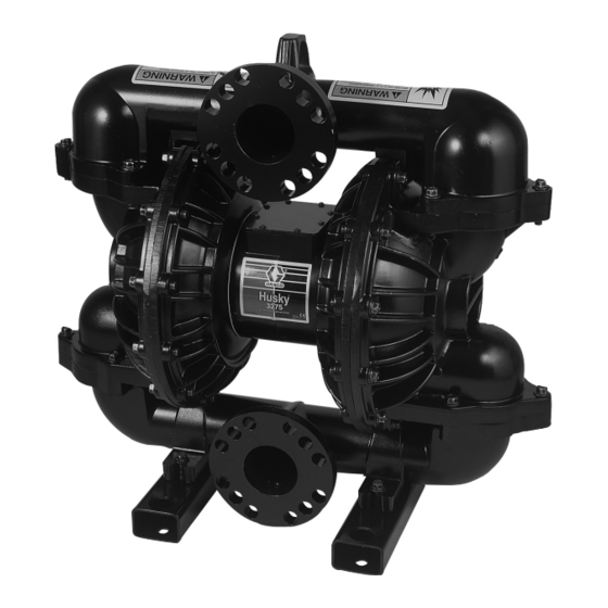
Huskyt3275 Air-Operated
Diaphragm Pump
3-inch pump for fluid transfer applications. For professional use only.
120 psi (0.8 MPa, 8 bar) Maximum Incoming Air Pressure
120 psi (0.8 MPa, 8 bar) Maximum Fluid Working Pressure
* Part No. DK3XXX
Part No. 232505 Private-Label Aluminum 3275 Pump (See page 20.)
Part No. 24D619 Private-Label Aluminum 3275 Pump (See page 20.)
* This model is
US and Foreign Patents Pending
Important Safety Instructions
Read all warning and instructions in this
manual. Save these instructions.
Refer to the Pump Matrix on page 20 to
determine the Part No. of your pump.
Contents
. . . . . . . . . . . . . . . . . . . . . . . . . . . . . . .
. . . . . . . . . . . . . . . . . . . . . . . . . . . . . .
. . . . . . . . . . . . . . . . . . . . . . . . . . . . . . .
. . . . . . . . . . . . . . . . . . . . . . . . . . . .
. . . . . . . . . . . . . . . . . . . . . . . . .
. . . . . . . . . . . . . . . . . . . . . . . . . . . . . . . .
. . . . . . . . . . . . . . . . . . . . . . . . . . . .
. . . . . . . . . . . . . . . . . . . . . . . .
. . . . . . . . . . . . . . . . . . . . . . . . . . .
. . . . . . . . . . . . . . . . . . . . . . . . . . . . . .
. . . . . . . . . . . . . . . . . . . . . . . . . .
. . . . . . . . . . . . . . . . . . . . . . .
. . . . . . . . . . . . . . . . . . . . .
. . . . . . . . . . . . . . . . . . . . . . .
certified.
2
4
9
10
11
12
20
21
22
23
24
25
. . . . . . . . . . . . . . . . . . .
26
27
. . . . . . . . . . . . . . . .
30
30
308639L
ENG
06317
Advertisement
Table of Contents

Related Manuals for Graco husky 3275


Summary of Contents for Graco husky 3275
-
Page 1: Table Of Contents
..... 06317 Graco Standard Warranty .... -
Page 2: Warnings
D Never alter or modify any part of this equipment; doing so could cause it to malfunction. Use only genuine Graco parts and accessories. D Check all equipment regularly and repair or replace worn or damaged parts immediately. - Page 3 WARNING HAZARDOUS FLUIDS Improper handling of hazardous fluids or inhaling toxic vapors can cause extremely serious injury or death from to splashing in the eyes, ingestion, or bodily contamination. Observe all the following precautions when handling known or potentially hazardous fluids. D Know what fluid you are pumping and its specific hazards.
-
Page 4: Installation
ELECTRIC SHOCK HAZARD assistance in planning a system to suit your needs. This pump must be grounded. The D Always use genuine Graco parts and accessories. steps for grounding may differ from the way you ground other pumps. Read and... - Page 5 Installation FLOOR-MOUNT TYPICAL INSTALLATION A Air supply hose B Bleed-type master air valve (required for pump) C Air regulator D Air line quick disconnect E Master air valve (for accessories) F Air line filter G Fluid suction hose H Fluid supply Ball valve (for releasing collected moisture) L Fluid outlet hose N Air inlet port...
- Page 6 WARNING pump, hoses, and accessories, as well as the stress caused during operation. Graco always recommends that you use grounded fluid hoses to dissipate static electricity. When D For all mountings, be sure the pump is secured with pumping non-conductive flammable fluids, groun- screws through the mounting feet (58).
- Page 7 Installation Air Exhaust Ventilation WARNING hanging Manifold Orientation (See Fig. 6 on page 14) TOXIC FLUID HAZARD Be sure to read and follow the USING The outlet manifold (50) and inlet manifold (53) can be HAZARDOUS FLUIDS, and FIRE OR rotated to best suit your installation needs.
- Page 8 Installation VENTING EXHAUST AIR A Air supply line B Bleed-type master air valve (required for pump) C Air regulator D Air Line quick disconnect E Master air valve (for accessories) F Air line filter Ball valve (for releasing collected moisture) P Muffler T Grounded air exhaust hose U Container for remote air exhaust...
-
Page 9: Operation
Operation Pressure Relief Procedure 3. Place the suction tube (if used) in the fluid to be pumped. WARNING NOTE: If the inlet pressure to the pump is more than 25 percent of the outlet working pressure, the To reduce the risk of serious injury, including ball check valves will not close fast enough, splashing fluid in the eyes or on the skin, follow this resulting in inefficient pump operation. -
Page 10: Maintenance
Maintenance Lubrication Tightening Connections The air valve is designed to operate unlubricated. Before each use, check all hoses for wear or damage, and replace them as necessary. Check to be sure all If lubrication is desired, every 500 hours of operation connections are tight and leak free. -
Page 11: Troubleshooting
Troubleshooting WARNING To reduce the risk of serious injury, including splashing fluid in the eyes or on the skin, follow the Pressure Relief Procedure on page 9. You must do this whenever this manual instructs you to relieve pressure, when you shut off the pump, and before checking, adjusting, cleaning, moving, or repairing any system equipment. -
Page 12: Service
Service Repairing the Air Valve Tools Required D Torque wrench 3. Move the main valve (6) to the center position, and pull it out of the cavity. Using a needle-nose pliers, D 7-mm or 9/32-in. socket wrench or TorxR pull the pilot block (16) straight up and out of the screwdriver T20 cavity. - Page 13 Service Reassembly For steps 1 to 3, see Fig. 5. 6. Grease the u-cup seals (9). Insert the actuator pistons in the bearings (8) wide end first. Leave 1. If you removed the bearings (8 and 17), install new the narrow end of each piston exposed in the valve ones and reassemble the fluid section as cavity.
- Page 14 Service Ball Check Valve Repair Torque to 55 to 60 ft-lb (75 to 81 NSm). See Torque Sequence, page 25. Tools Required D Torque wrench The ball seat is on the same side as the step for the o-ring (102). D 15-mm socket wrench To ensure proper seating, visually check that the manifold (50 or 53) is centered on the fluid covers...
- Page 15 Service Diaphragm Repair Tools Required D Torque wrench NOTE: A Fluid Section Service Kit is available. See the Repair Kit Matrix on page 21 to find the correct kit D 15-mm socket wrench for your pump. Parts included in the kit are marked with an asterisk in the Parts Drawing on page 22, for D 15/16-in.
- Page 16 Service Disassembly Reassembly (See Fig. 8) 1. Relieve the pressure. 1. Install each u-cup seal (15) so the lips face away from the center of the pump. Lubricate the u-cup seals. WARNING 2. Install a diaphragm assembly on one end of the To reduce the risk of serious injury whenever you shaft (14) as follows: are instructed to relieve pressure, always follow the...
- Page 17 Service Cutaway View with Diaphragms in Place Cutaway View with Diaphragms Removed 06327 06328 Lips face out of housing (1). 06329A Side marked AIR SIDE must face center housing (2). Grease. Torque to 100 to 120 ft-lb (136 to 163 NSm). Used only in models with PTFE diaphragms.
- Page 18 Service Removing and Replacing Bearings and Air Gasket (See Fig. 9) Tools Required D Torque wrench 6. Remove the air cover gaskets (10). Always replace the gaskets with new ones. D 13-mm socket wrench 7. Use a bearing puller to remove the diaphragm D Bearing puller shaft bearings (13), piston actuator bearings (8), and push pin bearings (17).
- Page 19 Service Detail of Bearings Press-fit bearings flush with surface of center housing (2). Torque to 19 to 21 ft-lb (26 to 28 NSm). 06330 through hole must be on bottom 06331 Fig. 9 308639...
-
Page 20: Pump Matrix
Pump Matrix Husky 3275 Pumps, Series C Your Model No. is marked on the pump’s serial plate. To determine the Model No. of your pump from the following matrix, select the six digits that describe your pump, working from left to right. The first digit is always D, designating Husky diaphragm pumps. -
Page 21: Repair Kit Matrix
Repair Kit Matrix For Husky 3275 Pumps, Series C Repair kits may be ordered separately. To repair the air valve, order the Air Valve Service Kit, Part No. 238765 (see page 23). Parts included in the Air Valve Service Kit are marked with a symbol in the Air Motor Parts List, for example (3{). -
Page 22: Parts Drawing
Parts Drawing 303}* 301* 201* 102* 101* *}302 201* 102* 101* Included in Fluid Section Service Kit. See the 06316A Repair Kit Matrix on page 21 to find the correct kit for your pump. { Included in Air Valve Service Kit 238765, which may be purchased separately. -
Page 23: Parts Lists
Parts Lists Air Motor Parts List (Matrix Column 2) Fluid Section Parts List (Matrix Column 3) Ref. Ref. Digit Part No. Description Qty. Digit Part No. Description Qty. 190830 MANIFOLD, outlet; 190827 COVER, air; aluminum aluminum 190826 HOUSING, center; 190828 COVER, fluid;... -
Page 24: Technical Data
Parts Lists Seat Parts List (Matrix Column 4) Diaphragm Parts List (Matrix Column 6) Ref. Ref. Digit Part No. Description Qty. Digit Part No. Description Qty. 101* 190840 SEAT; 316 SST 301* 190839 DIAPHRAGM; TPE 102* 113449 O-RING; PTFE 113265 SEAL, u-cup;... -
Page 25: Torque Sequence
Torque Sequence Always follow torque sequence when instructed to torque fasteners. 1. Left/Right Fluid Cover 3. Outlet Manifold Torque bolts to 55–60 ft–lb (75–81 NSm) Torque bolts to 55–60 ft–lb (75–81 NSm) SIDE VIEW TOP VIEW 2. Inlet Manifold Torque bolts to 55–60 ft–lb (75–81 NSm) BOTTOM VIEW 308639... -
Page 26: Dimensional Drawings
Dimensional Drawings Fluid inlet (bottom FRONT VIEW Four 0.84 in. manifold) and fluid 15.25 in. (21.5 mm) holes outlet (top manifold): (387.5 mm) (ANSI) 3.25 in. (83 mm) dia. I.D. Eight 0.84 in. (21.5 mm) holes (DIN) 28.6 in. 20.3 in. (727 mm) (516 mm) 24.5 in. -
Page 27: Performance Charts
Performance Charts Aluminum Husky 3275 Fluid Outlet Pressure Test Conditions: Pump tested in water with inlet submerged. (0.98, 9.8) Fluid Pressure Curves (0.8, 8) A at 120 psi (0.8 MPa, 8 bar) air pressure B at 100 psi (0.7 MPa, 7 bar) air pressure (0.7, 7) - Page 28 Performance Charts Aluminum Husky 3275 Air Consumption Test Conditions: Pump tested in water with inlet submerged. Ë Ë Ë Ë (9.8) Air Consumption Curves Ë Ë Ë Ë Ë Ë Ë Ë A at 120 psi (0.8 MPa, 8 bar) air pressure Ë...
- Page 29 Notes 308639...
-
Page 30: Graco Standard Warranty
With the exception of any special, extended, or limited warranty published by Graco, Graco will, for a period of five years from the date of sale, repair or replace any part of the equipment determined by Graco to be defective.