Table of Contents
Advertisement
INSTRUCTIONS-PARTS LIST
This manual contains important
warnings and information.
READ AND KEEP FOR REFERENCE.
INSTRUCTIONS
– For Water-Based Materials Only –
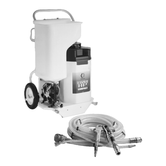
ELECTRIC TEXTURE SPRAYER WITH COMPRESSOR
TexSpray Compact HP
100 psi (7 bar) Maximum Working Pressure
Power
Model
Description
120V,
231–780
Sprayer Model 231–801 with 1 in. fluid
60 Hz
hose, 3/8 in. air hose and Trigger Gun
231–782
Sprayer Model 231–801 with 1 in. fluid
hose, 3/8 in. air hose and Flex Gun
231–783
Sprayer Model 231–801 with 1 in. fluid
hose, 3/8 in. air hose and 3 ft Pole Gun
240V,
231–788
Sprayer Model 231–803 with 1 in. fluid
50 Hz
hose, 3/8 in. air hose and Trigger Gun
231–790
Sprayer Model 231–803 with 1 in. fluid
hose, 3/8 in. air hose and Flex Gun
231–791
Sprayer Model 231–803 with 1 in. fluid
hose, 3/8 in. air hose and 3 ft Pole Gun
GRACO INC. P.O. BOX 1441 MINNEAPOLIS, MN 55440–1441
COPYRIGHT 1997, GRACO INC.
Graco Inc. is registered to I.S. EN ISO 9001
308–718
Supercedes Rev. B
First choice when
quality counts.
Rev. C
7068A
Advertisement
Table of Contents

Related Manuals for Graco TexSpray Compact HP


Summary of Contents for Graco TexSpray Compact HP
- Page 1 231–791 Sprayer Model 231–803 with 1 in. fluid hose, 3/8 in. air hose and 3 ft Pole Gun 7068A GRACO INC. P.O. BOX 1441 MINNEAPOLIS, MN 55440–1441 COPYRIGHT 1997, GRACO INC. Graco Inc. is registered to I.S. EN ISO 9001...
-
Page 2: Table Of Contents
This equipment is for professional use only. Read all instruction manuals, tags, and labels before operating the equipment. Use the equipment only for its intended purpose. If you are not sure, call Graco Technical Assis- tance at 1–800–543–0339. Do not expose the system to rain. Always store the system indoors. -
Page 3: Warnings
WARNING TOXIC FLUID HAZARD Hazardous fluid or toxic fumes can cause serious injury or death if splashed in the eyes or on the skin, inhaled, or swallowed. Know the specific hazards of the fluid you are using. Store hazardous fluid in an approved container. Dispose of hazardous fluid according to all local, state and national guidelines. -
Page 4: Component Identification And Function
Component Identification and Function Open Closed 7136A Located inside hopper 7069A Fig. 1 Air Outlet Provides quick disconnect connection for air supply to spray gun Pump Outlet Fitting Provides connection for hose and fluid supply to spray gun Air Pressure Regulator Adjusts air pressure to control air pressure to pump ON/OFF Switch Power switch that controls 120/240 Vac power to sprayer... -
Page 5: Preparation
Preparation Compressor Break-in 2. To install the hopper, position the hopper drain over the pump inlets while tilting the hopper very The first time you use the system, run the compressor slightly forward. As you engage the inlets, under no load to break it in, improve performance and straighten the hopper and push down. - Page 6 Preparation Setup the System Located inside hopper 1. Connect the hoses and gun as shown See Fig. 4. Fig. 8 07073A Fig. 7 7072A Using an Auxiliary Air Compressor An external air compressor may be connected (adapt- er included) to the auxiliary air compressor port (L) to 2.
- Page 7 Preparation 5. Always have the fluid hose installed when there is WARNING material in the hopper. If the hose is removed, the hopper will drain out through the pump. PRESSURIZED EQUIPMENT HAZARD The system pressure must be manually relieved to WARNING prevent the system from starting or spraying acci- dentally.
- Page 8 Preparation Wet the Hose Before Pumping Texture Mix the Material Material CAUTION Wet the inside of the hose before each use to flush out sediment and to prevent the texture material from This system is designed for use with only certain packing out the hose.
-
Page 9: Startup
Startup Prime the System 1. Fill the hopper (J) with the prepared texture material. 2. Install a tip. Refer to the Tip Selection Chart on page 10. 3. Open the gun air valve (423) to be sure air pres- sure is relieved and then close it again; the system primes easier if no air is supplied to the gun. -
Page 10: Spray Techniques
Spray Techniques Tip Selection Chart To Get Less Material Try any one or a combination of these methods. Application Tip Orifice Air Volume 1/8 in. High 1. Screw in the gun fluid regulator knob (418). Simulated 3/16 in. 2. Use a smaller tip. (fine, or small Acoustic confined areas) - Page 11 Spray Techniques How to Prevent Material Surge at the Beginning of a Spray Pattern Squeeze the trigger slowly to the fully triggered posi- tion while moving the gun quickly. For Continuous Spraying Use the trigger bail (401) to hold the trigger open to reduce operator fatigue.
-
Page 12: Shutdown And Cleanup
Shutdown and Cleanup 1. Fig. 15. and 16. Be sure the compressor pressure NOTE: In cold weather, store the system where it will is relieved – gun air valve (423) open. Close the not freeze. If it does freeze, thaw it thoroughly before gun air valve again. - Page 13 Shutdown and Cleanup Open Closed Fig. 15 7136A Oil here Fig. 17 Fig. 16 308–718...
-
Page 14: Pump Maintenance
Pump Maintenance For pump maintenance, troubleshooting and/or repair, see Manual 308–781. Troubleshooting WARNING To reduce the risk of injury, follow the Pressure Relief Procedure on page 7. System Troubleshooting PROBLEM CAUSE SOLUTION Compressor does not start. Trapped air pressure. Relieve air pressure by connecting air hose and opening gun air valve. - Page 15 Troubleshooting PROBLEM CAUSE SOLUTION No material output from pump Air valve is stalled. Reset the pump. See Fig. (continued) 1. Open air to the gun. 2. Turn the unit off. 3. Move the reset handle (122) in the direction of least resistance (about 15 lb.
- Page 16 Troubleshooting PROBLEM CAUSE SOLUTION Material pulses or surges. Triggering too fast. Squeeze trigger slowly to fully open position while moving gun quickly in a circular motion. Leaky or damaged duck bills. Clean and inspect duck bills. Note: Match pump part number with the correct pump breakdown in 308–781.
-
Page 17: Compressor Repair
Compressor Repair 3. Fig. 18. Remove two screws (26A) and loosen two WARNING screws (26B). Move pump (35) out of the way. HOT SURFACE HAZARD 4. Remove filter cover (20). Be sure the compressor duct work is cool before removing it. If the sprayer 5. - Page 18 Compressor Repair 9. Fig. 19. Tip TexSpray horizontal. Graco offers repair kits for the two cylinder compres- sor. The repair kits are listed in the Accessories. 10. Loosen hose clamps (28) and pull out hose (31). NOTE: For repair assistance or for compressor ser- 11.
-
Page 19: Cooler Repair
Cooler Repair 1. Follow the Pressure Relief Procedure on WARNING page 2. 2. Loosen the clamp (28) on the hose (29) and HOT SURFACE HAZARD remove the hose from the cooler (27). See Fig. 20. Be sure the compressor duct work is cool before removing it. - Page 20 Notes 308–718...
-
Page 21: Parts - Sprayer
Parts – Sprayer Model 231–801 and 231–803 23(Ref) 29(Ref) 9(Ref) White Black Black White Green White 36(Ref) Black Green 37(Ref) 7083B 308–718... - Page 22 Parts – Sprayer Model 231–801 and 231–803, Series A with 1 in. fluid hose, 3/8 in. air hose, and gun. Ref. Part No. Description Part No. Description Qty. 192–243 FRAME, TexSpray twin 113–812 HOSE, air, 3/8 in. x 3 in. 113–807 WHEEL, flat free urethane 290–491...
-
Page 23: Accessories
10 gallons (38 liters) *Measured while spraying at 1 m. Measured per ISO-3744. Graco Phone Number TO PLACE AN ORDER , contact your Graco distributor, or call this number to identify the distributor closest to you: 1–800–367–4023 Toll Free 308–718... -
Page 24: Graco Warranty
Graco distributor to the original purchaser for use. With the exception of any special extended or limited warranty published by Graco, Graco will, for a period of twelve months from the date of sale, repair or replace any part of the equipment determined by Graco to be defective.