Table of Contents
Advertisement
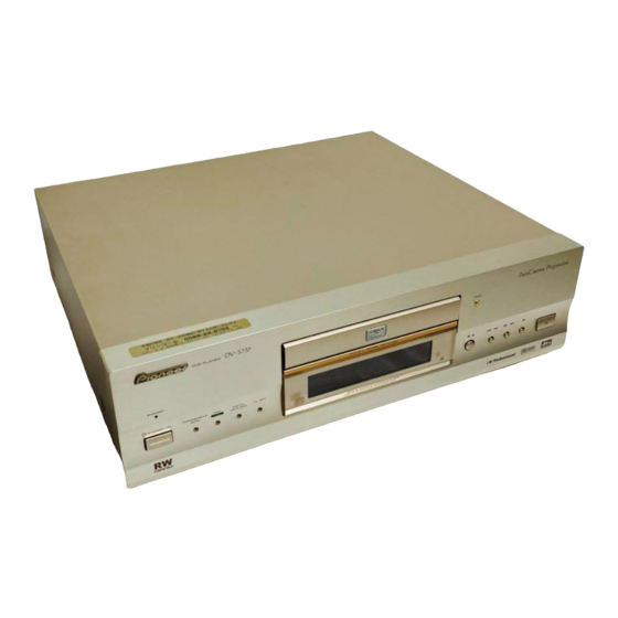
DVD PLAYER
DV-37
DV-S77
DV-S737
DV-737
DV-737-K
THIS MANUAL IS APPLICABLE TO THE FOLLOWING MODEL(S) AND TYPE(S).
Type
DV-37
DV-S77 DV-S737 DV-737 DV-737-K
KU/CA
-
LB
-
RL
-
-
RL/RD
-
-
WY
-
-
CONTENTS
1. SAFETY INFORMATION ....................................... 2
2. EXPLODED VIEWS AND PARTS LIST ................. 4
4. PCB CONNECTION DIAGRAM ........................... 39
5. PCB PARTS LIST ................................................ 52
6. ADJUSTMENT ..................................................... 58
PIONEER CORPORATION
PIONEER ELECTRONICS SERVICE, INC. P.O. Box 1760, Long Beach, CA 90801-1760, U.S.A.
PIONEER EUROPE NV Haven 1087, Keetberglaan 1, 9120 Melsele, Belgium
PIONEER ELECTRONICS ASIACENTRE PTE. LTD. 253 Alexandra Road, #04-01, Singapore 159936
c
PIONEER CORPORATION 2000
Model
-
-
-
-
-
-
-
-
-
-
-
4-1, Meguro 1-chome, Meguro-ku, Tokyo 153-8654, Japan
Power Requirement
AC120V
AC110V
AC110-127V/220-240V
AC110-127V/220-240V
AC220-240V
7. GENERAL INFORMATION ................................ 61
7.1 DIAGNOSIS .................................................. 61
7.1.1 TEST POINTS LOCATION ................... 61
7.1.2 TEST MODE SCREEN DISPLAY ........ 62
7.1.3 TROUBLE SHOOTING ........................ 64
7.1.4 ERROR CODE ..................................... 65
7.1.5 DISASSEMBLY .................................... 69
7.2 IC .................................................................. 70
T - IZE AUG. 2000 Printed in Japan
ORDER NO.
RRV2320
Region No.
Remarks
1
3
3
4
2
Advertisement
Table of Contents

Related Manuals for Pioneer DV-37


Summary of Contents for Pioneer DV-37
-
Page 1: Table Of Contents
PIONEER CORPORATION 4-1, Meguro 1-chome, Meguro-ku, Tokyo 153-8654, Japan PIONEER ELECTRONICS SERVICE, INC. P.O. Box 1760, Long Beach, CA 90801-1760, U.S.A. PIONEER EUROPE NV Haven 1087, Keetberglaan 1, 9120 Melsele, Belgium PIONEER ELECTRONICS ASIACENTRE PTE. LTD. 253 Alexandra Road, #04-01, Singapore 159936 PIONEER CORPORATION 2000 T –... -
Page 2: Safety Information
The use of a substitute replacement component which does Leakage 0.5mA current Device not have the same safety characteristics as the PIONEER tester under recommended replacement one, shown in the parts list in test this Service Manual, may create shock, fire, or other hazards. - Page 3 DV-37, DV-S77, DV-S737, DV-737, DV-737-K WARNING ! THE AEL (ACCESSIBLE EMISSION LEVEL) OF THE LASER POWER OUTPUT IS LESS THAN CLASS 1 BUT THE LASER COMPONENT IS CAPABLE OF EMITTING RADIATION EXCEEDING THE LIMIT FOR CLASS 1. A SPECIALLY INSTRUCTED PERSON SHOULD DO SERVICING OPERATION OF THE APPARATUS.
-
Page 4: Exploded Views And Parts List
DV-37, DV-S77, DV-S737, DV-737, DV-737-K 2. EXPLODED VIEWS AND PARTS LIST • NOTES: Parts marked by "NSP" are generally unavailable because they are not in our Master Spare Parts List. • mark found on some component parts indicates the importance of the safety factor of the part. - Page 5 (English, French, German, Italian) Operating Instructions See Contrast table (2) (Dutch, Swedish, Spanish, Danish) (2) CONTRAST TABLE DV-37/KU/CA, DV-S77/LB, DV-S737/RL, RL/RD, DV-737/WY and DV-737-K/WY are constructed the same except for the following : Part No. Mark No. Symbol and Description...
- Page 6 DV-37, DV-S77, DV-S737, DV-737, DV-737-K 2.2 EXTERIOR SECTION RL, RL/RD and WY Types Only Refer to "2.4 LOADING MECHANISM ASSY". RL, RL/RD and WY Types LB, RL and RL/RD Only Types Only KU/CA and KU/CA Type LB Types Only Only...
- Page 7 Clamper Plate VNE2068 Label See Contrast table (2) Screw See Contrast table (2) (2) CONTRAST TABLE DV-37/KU/CA, DV-S77/LB, DV-S737/RL, RL/RD, DV-737/WY and DV-737-K/WY are constructed the same except for the following : Part No. Mark No. Symbol and Description DV-37 DV-S77...
- Page 8 DV-37, DV-S77, DV-S737, DV-737, DV-737-K 2.3 FRONT PANEL SECTION KU/CA and LB Types Only 16 (2/2) 16 (1/2) 14 or 15...
- Page 9 Main Key See Contrast table (2) Screw BBZ30P080FCC Remote Control Sheet AEE7021 (2) CONTRAST TABLE DV-37/KU/CA, DV-S77/LB, DV-S737/RL, RL/RD, DV-737/WY and DV-737-K/WY are constructed the same except for the following : Part No. Mark No. Symbol and Description DV-37 DV-S77...
- Page 10 DV-37, DV-S77, DV-S737, DV-737, DV-737-K 2.4 LOADING MECHANISM ASSY • Top View • Bottom View Refer to "TRAVERSE MECHANISM ASSY-S". • LOADING MECHANISM ASSY PARTS LIST Mark No. Description Part No. Mark No. Description Part No. Traverse Mechanism Assy-S VXX2653...
- Page 11 DV-37, DV-S77, DV-S737, DV-737, DV-737-K 2.5 TRAVERSE MECHANISM ASSY-S • Top View • TRAVERSE MECHANISM ASSY-S PARTS LIST Mark No. Description Part No. Mark No. Description Part No. SMEB Assy VWG2048 Hook VNL1770 FFC Holder VNL1802 FGSB Assy VWG2009 Motor (CARRIAGE)
-
Page 12: Block Diagram And Schematic Diagram
DV-37, DV-S77, DV-S737, DV-737, DV-737-K 3. BLOCK DIAGRAM AND SCHEMATIC DIAGRAM 3.1 BLOCK DIAGRAM VIDEO IC805 (RF) DATA Spindle 57-60 80-84 (24P) MB81F161622C-80FN IC701 Motor 63-66 78,86,87 (24P) CN120 OEIC IC101 DSPRF ROMXA 16M SDRAM PE5108A (RF) CDLRCK LA9710M DVD Decoder... - Page 13 DV-37, DV-S77, DV-S737, DV-737, DV-737-K VJKB ASSY IC604 JA603 TK15420M (Cb) (Cb) COMPONENT IC603 (Cr) VIDEO OUT TK15420M IC603 (Cr) TK15420M JA602 IC601 TK15420M S-VIDEO OUT (28P) CN611 (28P) CN103 IC602 TK15420M IC601 JA601 (Cb) TK15420M (Cr) VIDEO OUT RY601...
- Page 14 DV-37, DV-S77, DV-S737, DV-737, DV-737-K 3.2 LOMB, LOSB, SMEB, FGSB, MSWB ASSYS and OVERALL WIRING DIAGRAM AJKB ASSY (KU/CA, LB, RL, RL/RD : VWV1761) (WY : VWV1762) WY ONLY ONLY SCRB ASSY (VWV1793) RL, RL/RD, WY ONLY DJKB ASSY (KU/CA, LB : VWV1788)
- Page 15 DV-37, DV-S77, DV-S737, DV-737, DV-737-K Note : When ordering service parts, be sure to refer to "EXPLODED VIEWS and PARTS LIST" or "PCB PARTS LIST". (RF) : RF SIGNAL ROUTE : SLIDER SERVO LOOP LINE (SP) : SPINDLE SERVO LOOP LINE...
- Page 16 DV-37, DV-S77, DV-S737, DV-737, DV-737-K 3.3 DVDM ASSY (1/5) DVDM ASSY (KU/CA, LB : VWS1416) (RL, RL/RD, WY : VWS1419) HN1A01F HN1A01F (RF) (RF) (RF) (CD) (CD) HN1C01FU (RF) (RF) HN1C01FU RF IC HN1C01F HN1B04FU HN1B04FU HN1C01FU HN1C01FU HN1A01F (RF)
- Page 17 DV-37, DV-S77, DV-S737, DV-737, DV-737-K (RF) : RF SIGNAL ROUTE (CD) : CD DATA SIGNAL ROUTE : FOCUS SERVO LOOP LINE : TRACKING SERVO LOOP LINE : SLIDER SERVO LOOP LINE (SP) : SPINDLE SERVO LOOP LINE (RF) KU/CA, LB...
- Page 18 DV-37, DV-S77, DV-S737, DV-737, DV-737-K 3.4 DVDM ASSY (2/5) DVDM ASSY (KU/CA, LB : VWS1416) (RL, RL/RD, WY : VWS1419) TC55V1001AF8 WORK SRAM PGM 16M FLASH MEMORY VYW1738 20MHz SH1 BASE ASIC...
- Page 19 DV-37, DV-S77, DV-S737, DV-737, DV-737-K : AUDIO SIGNAL ROUTE (DIGITAL) HN1B04FU CN901 HN1B04FU 3 → 5 CONVERTER 5 → 3 CONVERTER CN101 1/5,3/5...
- Page 20 DV-37, DV-S77, DV-S737, DV-737, DV-737-K 3.5 DVDM ASSY (3/5) DVDM ASSY (KU/CA, LB : VWS1416) (RL, RL/RD, WY : VWS1419) MNR4800DJ7-TBB 4M DRAM BY CHIP (RF) (RF)
- Page 21 DV-37, DV-S77, DV-S737, DV-737, DV-737-K RL, RL/RD, WY ONLY (RF) 16M SDRAM 16M SDRAM : RF SIGNAL ROUTE (CD) : CD DATA SIGNAL ROUTE MB81F161622C-80FN MB81F161622C-80FN : AUDIO SIGNAL ROUTE : AUDIO SIGNAL ROUTE (DIGITAL) : VIDEO SIGNAL ROUTE 1M × 16 EDO DRAM (TSOP)
- Page 22 DV-37, DV-S77, DV-S737, DV-737, DV-737-K 3.6 DVDM ASSY (4/5) DVDM ASSY (KU/CA, LB : VWS1416) : AUDIO SIGNAL ROUTE (RL, RL/RD, WY : VWS1419) : AUDIO SIGNAL ROUTE (DIGITAL) CLOCK GEN. BLOCK CN101...
- Page 23 DV-37, DV-S77, DV-S737, DV-737, DV-737-K...
- Page 24 DV-37, DV-S77, DV-S737, DV-737, DV-737-K 3.7 DVDM ASSY (5/5) DVDM ASSY (KU/CA, LB : VWS1416) (RL, RL/RD, WY : VWS1419) SGRAM VQE-3 VIDEO ENCODER IC...
- Page 25 DV-37, DV-S77, DV-S737, DV-737, DV-737-K : VIDEO SIGNAL ROUTE : Y SIGNAL ROUTE : C SIGNAL ROUTE (Cr) : CR SIGNAL ROUTE (Cb) : Cb SIGNAL ROUTE : Y SIGNAL ROUTE VQE-5 2/5,3/5 (Cb) (Cb) (Cb) (Cb) VKN1618 (Cr) (Cr)
- Page 26 DV-37, DV-S77, DV-S737, DV-737, DV-737-K 3.8 AJKB ASSY AJKB ASSY (KU/CA, LB, RL, RL/RD : VWV1761) (WY : VWV1762) CN122...
- Page 27 DV-37, DV-S77, DV-S737, DV-737, DV-737-K : AUDIO SIGNAL ROUTE AD1854JRS CN402 ONLY AD1854JRS : The power supply is shown with the marked box.
- Page 28 DV-37, DV-S77, DV-S737, DV-737, DV-737-K 3.9 DJKB ASSY DJKB ASSY (KU/CA, LB : VWV1788) (RL, RL/RD, WY : VWV1789) CN104...
- Page 29 DV-37, DV-S77, DV-S737, DV-737, DV-737-K : AUDIO SIGNAL ROUTE (DIGITAL) : The power supply is shown with the marked box. OPTICAL COAXIAL KU/CA, LB ONLY RL, RL/RD, WY ONLY...
- Page 30 DV-37, DV-S77, DV-S737, DV-737, DV-737-K 3.10 VJKB ASSY (Cr) (Cr) (Cb) (Cb) CN103 WY ONLY LB, RL, RL/RD, WY ONLY L783(R783) WY ONLY L788(R788) L789(R789) L790(R790) L791(R791) (Cr) (Cr) L792(R792) (Cr) (Cr) L783, L788-L792 : VTL1076 WY ONLY (Cb) (Cb)
- Page 31 DV-37, DV-S77, DV-S737, DV-737, DV-737-K : The power supply is shown with the marked box. VJKB ASSY (KU/CA : VWV1791) (LB, RL, RL/RD : VWV1790) (WY : VWV1792) L701 (R701) VTL1082 L704 WY ONLY (R704) VTL1082 L707 (R707) VTL1082 L710...
- Page 32 DV-37, DV-S77, DV-S737, DV-737, DV-737-K 3.11 SCRB ASSY (DV-737/WY and DV-737-K/WY ONLY) SCRB ASSY (VWV1793) CN102 CN692 (C/R) (Y/V) (Y/V) (C/R)
- Page 33 DV-37, DV-S77, DV-S737, DV-737, DV-737-K : The power supply is shown with the marked box. : AUDIO SIGNAL ROUTE : R SIGNAL ROUTE : VIDEO SIGNAL ROUTE : Y SIGNAL ROUTE : G SIGNAL ROUTE : C SIGNAL ROUTE : B SIGNAL ROUTE...
-
Page 34: Flky And Pwsb Assys
DV-37, DV-S77, DV-S737, DV-737, DV-737-K 3.12 FLKY and PWSB ASSYS KU/CA : 36k LB : 62k RL, RL/RD, WY RL, RL/RD : 68k ONLY WY : 20k S101-S104 : ASG7013 KU/CA : 6.2k LB : 47k RL, RL/RD : 27k... - Page 35 DV-37, DV-S77, DV-S737, DV-737, DV-737-K FLKY ASSY (KU/CA : VWG2214) PWSB ASSY (LB : VWG2215) (KU/CA : VWG2219) (RL, RL/RD : VWG2216) (LB : VWG2221) (WY : VWG2217) (RL, RL/RD, WY : VWG2220) ASG7013 KU/CA, LB : 820Ω RL, RL/RD, WY : 220Ω...
- Page 36 DV-37, DV-S77, DV-S737, DV-737, DV-737-K 3.13 POWER SUPPLY UNIT RL, RL/RD, WY CN002 Short CN003 CN001 KU/CA, LB VZE1005 CAUTION : FOR CONTINUED PROTECTION AGAINST RISK OF FIRE. REPLACE ONLY WITH SAME TYPE NO. 19396T1.0, BY WICKMANN WERKE GMBH FOR P101 AND P102 (VZE1002).
- Page 37 DV-37, DV-S77, DV-S737, DV-737, DV-737-K POWER SUPPLY UNIT (VWR1333) NOTE OF SPARE PARTS IN POWER SUPPLY (SYPS) UNIT • In case of repairing, use the described parts only to prevent an accident. • Please write the red mark on the board when the primary section of POWER SUPPLY (SYPS) Unit is repaired.
- Page 38 DV-37, DV-S77, DV-S737, DV-737, DV-737-K WAVEFORMS Note : The encircled numbers denote measuring point in the schematic diagram. DVDM ASSY TP3 (RFO) V: 1V/div. H: 50nsec/div. (at DVD PLAY) TP6 (TE) V: 1V/div. H: 5msec/div. (at DVD PLAY) TP8 (FDO) V: 1V/div.
-
Page 39: Pcb Connection Diagram
DV-37, DV-S77, DV-S737, DV-737, DV-737-K 4. PCB CONNECTION DIAGRAM NOTE FOR PCB DIAGRAMS : 1. Part numbers in PCB diagrams match those in the schematic 3. The parts mounted on this PCB include all necessary parts for diagrams. several destinations. - Page 40 DV-37, DV-S77, DV-S737, DV-737, DV-737-K • This PCB is a four-layered board. 4.2 DVDM ASSY DVDM ASSY CN901 SIDE A VR1001 VR1831 IC1201 CN611 IC1003 IC1001 IC1007 IC1006 IC1005 IC891 IC915 IC916 IC914 IC806 IC801 CN101 IC901 IC904 IC952 IC957...
- Page 41 DV-37, DV-S77, DV-S737, DV-737, DV-737-K • This PCB is a four-layered board. DVDM ASSY SIDE B Q1620 Q1621 Q1712 Q1612 Q1610 Q1611 Q1511 Q1512 Q1510 Q1410 Q1411 Q1412 Q1310 Q1311 IC1002 Q1312 IC804 IC907 IC803 IC917 IC610 IC607 IC805 IC913...
- Page 42 DV-37, DV-S77, DV-S737, DV-737, DV-737-K 4.3 AJKB ASSY SIDE A AJKB ASSY CN402 (VNP1781-B) CN122 IC112 IC113 IC103 IC115 IC104 IC108 IC117 IC105 IC114 IC1080 IC109 IC106 IC107 IC1107...
- Page 43 DV-37, DV-S77, DV-S737, DV-737, DV-737-K SIDE B AJKB ASSY (VNP1781-B) Q106 Q104 Q102 Q105 Q103 Q101 Q115 Q116 Q114 Q113 IC102 IC101 Q117 IC103 Q119 Q118 Q120 IC111 IC110 Q111...
- Page 44 DV-37, DV-S77, DV-S737, DV-737, DV-737-K 4.4 DJKB ASSY DJKB ASSY CN104 SIDE A (VNP1781-B) SIDE B DJKB ASSY...
- Page 45 DV-37, DV-S77, DV-S737, DV-737, DV-737-K 4.5 VJKB ASSY VJKB ASSY CN491 CN103 SIDE A Q619 Q621 Q625 Q624 Q627 Q631 Q634 Q633 Q652 Q651 Q653 Q622 Q604 Q628 Q607 Q630 Q608 IC603 Q609 Q610 IC604 (VNP1781-B) Q618 IC601 Q605 Q606...
- Page 46 DV-37, DV-S77, DV-S737, DV-737, DV-737-K 4.6 FLKY and PWSB ASSYS SIDE A SIDE B...
- Page 47 DV-37, DV-S77, DV-S737, DV-737, DV-737-K PWSB ASSY CN105 FLKY ASSY (VNP1780-A) FLKY ASSY PWSB ASSY...
- Page 48 DV-37, DV-S77, DV-S737, DV-737, DV-737-K 4.7 SCRB ASSY (For WY Type) SCRB ASSY CN692 CN102 SIDE A (VNP1781-B) SIDE B Q404 Q401 Q405 Q406 Q409 SCRB ASSY Q403 Q407 Q408 Q402...
- Page 49 DV-37, DV-S77, DV-S737, DV-737, DV-737-K 4.8 MSWB ASSY (For RL, RL/RD and WY Types) MSWB ASSY SIDE A CN002 (VNP1780-A)
- Page 50 DV-37, DV-S77, DV-S737, DV-737, DV-737-K 4.9 POWER SUPPLY UNIT RL, RL/RD AC IN and WY POWER SUPPLY UNIT Types Only Q001 Q002 IC001 IC201 Q003 IC301 Q101 Q301 CN101 IC101 IC102 IC103 SIDE A...
- Page 51 DV-37, DV-S77, DV-S737, DV-737, DV-737-K POWER SUPPLY UNIT SIDE B...
-
Page 52: Pcb Parts List
DV-37, DV-S77, DV-S737, DV-737, DV-737-K Mark No. Description Part No. Mark No. Description Part No. 5. PCB PARTS LIST • NOTES: Parts marked by "NSP" are generally unavailable because they are not in our Master Spare Parts List. • mark found on some component parts indicates the importance of the safety factor of the part. - Page 53 DV-37, DV-S77, DV-S737, DV-737, DV-737-K Mark No. Description Part No. Mark No. Description Part No. DJKB ASSY VWV1788 and VWV1789 are constructed the same except for the following : Part No. Mark Symbol and Description Remarks VWV1788 VWV1789 S901 Not used...
- Page 54 ASG7013 ASG7013 Not used R206 RS1/16S821J RS1/16S821J RS1/16S221J J201 Cord with Plug DE010WC0 Not used DE010WC0 PCB PARTS LIST FOR DV-37/KU/CA UNLESS OTHERWISE NOTED Mark No. Description Part No. Mark No. Description Part No. IC351 M56788FP LOMB ASSY IC803 M5M4V18165DTP-6S...
- Page 55 DV-37, DV-S77, DV-S737, DV-737, DV-737-K Mark No. Description Part No. Mark No. Description Part No. C1019-C1021,C1027,C1302-C1304 CKSRYF105Z10 CAPACITORS C1402-C1404,C1502-C1504 CKSRYF105Z10 C612 CCSRCH100D50 C1602-C1604,C1702-C1704 CKSRYF105Z10 C1072,C123,C145,C583,C617 CCSRCH101J50 C1805-C1815,C1818,C1819,C1837 CKSRYF105Z10 C655,C727,C728,C959 CCSRCH101J50 C109,C110,C130,C161,C204,C215 CKSRYF105Z10 C216,C313 CCSRCH102J50 C104-C108,C126,C314,C333 CCSRCH150J50 C221,C222,C226,C230,C236,C255 CKSRYF105Z10 C298,C299,C319,C329,C430,C542 CKSRYF105Z10...
- Page 56 DV-37, DV-S77, DV-S737, DV-737, DV-737-K Mark No. Description Part No. Mark No. Description Part No. RESISTORS AJKB ASSY All Resistors RS1/16S SEMICONDUCTORS IC103,IC104 AD1854JRS OTHERS IC101,IC102 NJM5532MD JA901 OPTICAL LINK OUT GP1FA550TZ IC109 NJM78M05FA JA931,JA932 RKN1004 IC107 NJM78M09FA REMOTE CONTROL JACK...
-
Page 57: Flky Assy
DV-37, DV-S77, DV-S737, DV-737, DV-737-K Mark No. Description Part No. Mark No. Description Part No. RESISTORS SWITCHES R612,R614,R626,R627 RS1/16S1001F S101-S104,S106 ASG7013 R636,R637,R647,R656 RS1/16S1001F R608,R841,R842,R844,R845 RS1/16S1002F CAPACITORS R843 RS1/16S1802F C101 CEAT470M10 R610,R611,R646 RS1/16S2201F C104 CEAT470M16 C103,C117 CEJQ101M10 R651 RS1/16S3300F C111 CKSQYB102K50... -
Page 58: Adjustment
DV-37, DV-S77, DV-S737, DV-737, DV-737-K 6. ADJUSTMENT 6.1 ADJUSTMENT ITEMS AND LOCATION Adjustment Points (PCB Part) Adjustment Items [Electrical Part] DVDM ASSY Y Level Adjustment CN104 Component Y Level Adjustment VR1831 VR1001 27MHz Clock Adjustment CN103 : XZNRON1 : XANRH1... -
Page 59: Electrical Adjustment
DV-37, DV-S77, DV-S737, DV-737, DV-737-K 6.4 ELECTRICAL ADJUSTMENT Y Level Adjustment • Power ON • Play the DVD test disc DVDM ASSY 1Vp-p at the 100% color-bar signal part VR1001 VIDEO Player (Rear) START TV monitor Oscilloscope Probe (10:1) V: 20mV/div. - Page 60 DV-37, DV-S77, DV-S737, DV-737, DV-737-K 27MHz Clock Adjustment DVDM ASSY • Normal mode • Power ON 27.000000MHz ± 170Hz VC951 Player START DVDM ASSY CN103 - Pin 5 Frequency counter...
-
Page 61: General Information
DV-37, DV-S77, DV-S737, DV-737, DV-737-K 7. GENRAL INFORMATION 7.1 DIAGNOSIS 7.1.1 TEST POINTS LOCATION This model has not test terminal. Please use following points when checking the RF, FE and TE, etc.. DVDM ASSY (3V) (SREQ) (FE) (VREF) (RFO) (GNDS) -
Page 62: Test Mode Screen Display
DV-37, DV-S77, DV-S737, DV-737, DV-737-K 7.1.2 TEST MODE SCREEN DISPLAY When the test mode is entered, press the ESC button and the TEST button in order of the test mode remote control unit (GGF1067). Consecutive double-OSD display is supported during test mode. The screen is composed 10 lines with a maximum of 32 characters per line. - Page 63 DV-37, DV-S77, DV-S737, DV-737, DV-737-K (10) Output video system [V – ∗ ∗ ∗ ∗] (20) 1 Version of the flash ROM [V : ∗ . ∗ ∗ ∗] 2 Flash ROM size [FLSH = ∗] NTSC system [NTSC] PAL system [PAL ] (21) Revision of the system controller [S : ∗...
-
Page 64: Trouble Shooting
DV-37, DV-S77, DV-S737, DV-737, DV-737-K 7.1.3 TROUBLE SHOOTING • No Power ON • FL is not turned ON • FL indication is unusual START • Blow out fuse of the primary side Power ON • Blow out micro-fuse on the POWER SUPPLY Unit. (Check the each voltage.) (P101, P102, P103) •... -
Page 65: Error Code
DV-37, DV-S77, DV-S737, DV-737, DV-737-K 7.1.4 ERROR CODE Error codes that are displayed on the FL display without using the remote control unit FL Display Possible causes Operation of the unit The sound may not out AV1 VER AV-1 chip is not a match with the program of system controller with the specific audio. - Page 66 DV-37, DV-S77, DV-S737, DV-737, DV-737-K Description Causes if with a DVD Causes if with a CD Operation of the of Error SGC converge SGC could not converge during detects the peak Open timeout 41 Spindle timeout The unit did not enter Stop mode within 10 seconds of issuance of a Stop command.
- Page 67 DV-37, DV-S77, DV-S737, DV-737, DV-737-K Description Causes if with a DVD Causes if with a CD Operation of the Unit of Error ID can not read An ID could not be read for 1 second or more. Stop during tracing...
- Page 68 DV-37, DV-S77, DV-S737, DV-737, DV-737-K Error codes that are displayed on the FL display by using the remote control unit (Device error) To display : ESC + DISPLAY + DISPLAY ; Location of the display : At the two digits of left of the FL display...
-
Page 69: Disassembly
DV-37, DV-S77, DV-S737, DV-737, DV-737-K 7.1.5 DISASSEMBLY Traverse Mechanism Assy Remove the Bonnet. (Screws × 7) • Rear View Tray Open POWER ON DVDM Assy POWER SUPPLY Side Unit Side Short Short Open Open Short Switch Short Switch Power OFF. (Pull out the Power Cord from outlet.) - Page 70 DV-37, DV-S77, DV-S737, DV-737, DV-737-K 7.2 IC • The information shown in the list is basic information and may not correspond exactly to that shown in the schematic diagrams. • List of IC LC78652W, PD3410A, PM0024AF, PE5185A LC78652W (DVDM ASSY : IC201) •...
- Page 71 DV-37, DV-S77, DV-S737, DV-737, DV-737-K • Pin Function t f i − − l l i t t i y t i t l i − − − − a i l t l i −...
- Page 72 DV-37, DV-S77, DV-S737, DV-737, DV-737-K r r i t i r − − − − l a i t f i − − l l i l i f − t l i f t l i f t l i f −...
- Page 73 DV-37, DV-S77, DV-S737, DV-737, DV-737-K PD3410A (DVDM ASSY : IC601) • System Control IC • Pin Function − − − − − − − c t i − − − − − − − ← − − − − −...
- Page 74 DV-37, DV-S77, DV-S737, DV-737, DV-737-K − − − − − − − c t i − − c t i − c t i c t i c t i c t i − c t i − − −...
- Page 75 DV-37, DV-S77, DV-S737, DV-737, DV-737-K − t i s d i l t i s − − − − − − − l l o l a i e l l l a i e l l − e l l −...
- Page 76 DV-37, DV-S77, DV-S737, DV-737, DV-737-K − − − − − − − − − −...
- Page 77 DV-37, DV-S77, DV-S737, DV-737, DV-737-K PM0024AF (DVDM ASSY : IC1001) • Video Encoder IC • Pin Function − − c i t . ) r v i t y t i . ) r v i t y t i −...
- Page 78 DV-37, DV-S77, DV-S737, DV-737, DV-737-K − − − − Ω − t s i t s i µ − t i c t i c − t i c − t s i t s i t s i −...
- Page 79 DV-37, DV-S77, DV-S737, DV-737, DV-737-K − − − − − − − − − − − − − − − t i r − − − − − − −...
- Page 80 DV-37, DV-S77, DV-S737, DV-737, DV-737-K − t i r − − l l u − l l u − − l l u − l l u − − l l u − l l u − − l l u...
- Page 81 DV-37, DV-S77, DV-S737, DV-737, DV-737-K − t t i t t i l a i t t i t t i...
- Page 82 DV-37, DV-S77, DV-S737, DV-737, DV-737-K PE5185A (FLKY ASSY : IC101) • FL Control IC • Pin Function − − − n i l − − − − − t s i t s i − − − − − −...
- Page 83 DV-37, DV-S77, DV-S737, DV-737, DV-737-K − c t i n i l − − − − − t s i − −...
-
Page 84: Panel Facilities And Specifications
DV-37, DV-S77, DV-S737, DV-737, DV-737-K 8. PANEL FACILITIES AND SPECIFICATIONS 8.1 PANEL FACILITIES Front Panel (lllustration is KU/CA and LB types) STANDBY/ON button (KU/CA and LB types only) Remote sensor Press to switch the player on or to put in standby. -
Page 85: Display Window
DV-37, DV-S77, DV-S737, DV-737, DV-737-K Display Window 96 kHz indicator TOTAL indicator Indicates a DVD disc containing high-sampling rate (96 kHz) Indicates that the disc in the player is stopped and DISPLAY audio is playing. has been pressed. ANGLE indicator DTS indicator Indicates DTS audio playback. -
Page 86: Rear Panel
You only need to set this switch if you’re using an NTSC TV/ Use to connect this player to another component bearing the Pioneer Î mark. This lets you control this unit as though it monitor connected via the component video outputs of this player. - Page 87 Use to connect this player to another component bearing the or progressive scan signal (the 525p(480p) setting). Generally, Pioneer Î mark. This lets you control this unit as though it however, you should leave it set to MENU SELECT, which were a component in a system.
- Page 88 DV-37, DV-S77, DV-S737, DV-737, DV-737-K WY Type [ Easy Setup ] Connect to a composite video input on your TV using the supplied yellow video cable. AV CONNECTOR 525i 525p AV1(RGB) (480i) (480p) MENU SELECT COMPONENT VIDEO OUT S-VIDEO OUT...
- Page 89 DV-37, DV-S77, DV-S737, DV-737, DV-737-K [ Home theater audio connections ] Plug into a standard If your amplifier has analog inputs, AC wall outlet. connect to the left/right inputs. Otherwise, connect to a pair of stereo inputs. AV CONNECTOR 525i...
-
Page 90: Remote Control
DV-37, DV-S77, DV-S737, DV-737, DV-737-K Remote Control KU/CA Type (Buttons indicated with * are used for menu operation.) MENU button* Use to display or close the DVD menu screen. (standby/on) button Press to switch the player on or to put in standby. - Page 91 DV-37, DV-S77, DV-S737, DV-737, DV-737-K RETURN button* DIMMER (FL) button Use to go one menu back (current settings are maintained). Press to change the brightness of the FL display and disc Use RETURN when you do not want to change the option illumination in four steps: maximum brightness, medium setting in a menu.
- Page 92 & your TV. For example, If you have a Pioneer TV, press and hold CLEAR, then press 0, 0 on the remote control. 2. Confirm that the TV is responding to the programmed code.
- Page 93 DV-37, DV-S77, DV-S737, DV-737, DV-737-K * These butttons are used to navigate on-screen TOP MENU – displays the top menu of a menus. DVD disc. Joystick / ENTER button – move the MENU – displays DVD disc menu. joystick up/down/left/right to navigate on- Power –...
- Page 94 DV-37, DV-S77, DV-S737, DV-737, DV-737-K 8.2 SPECIFICATIONS KU/CA type Accessories Specifications Audio Cord (L=1.5m): VDE1033 General White System ...... DVD system and Compact Disc digital audio system Power requirements ..........AC 120 V, 60 Hz Power consumption ..............25 W Power consumption in standby mode ......
- Page 95 DV-37, DV-S77, DV-S737, DV-737, DV-737-K LB, RL and RL/RD types Accessories Specifications Audio cord ..................1 Video cord ..................1 General Power cord ..................1 System ...... DVD system and Compact Disc digital audio system Remote control unit ................ 1 Power requirements AA (R6P) dry cell batteries .............
- Page 96 DV-37, DV-S77, DV-S737, DV-737, DV-737-K WY type Specifications Accessories General Audio Cord (L=1.5m): VDE1033 System .... DVD system and Compact Disc digital audio system White Power requirements ........... 220-240 V, 50/60 Hz Power consumption ..............27 W Power consumption in standby mode ......less than 1 W Weight ..................