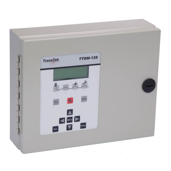
Pentair TRACETEK TTDM-128 Installation Instructions Manual
Leak detection master module
Hide thumbs
Also See for TRACETEK TTDM-128:
- Installation instructions manual (6 pages) ,
- Installation instructions manual (8 pages)
Advertisement
Quick Links
TRACETEK
TraceTek Leak DeTecTion MasTer MoDuLe insTaLLaTion insTrucTions
AppROvALS AND CERTIfICATIONS
TYPE NM
General Signaling Equipment
76LJ
IMpORTANT WARNINGS AND NOTES
THERMAL BUILDING SOLUTIONS
TTDM-128
The following icons are used extensively throughout this manual to alert you to important
warnings
that affect safety and to important notes
unit. Be sure to read and follow them carefully.
EN-TraceTekTTDM128-IM-H57341 04/16
GENERAL INfORMATION
Please read these instructions carefully and keep them in a safe
place (preferably close to the TTDM-128) for future reference.
These instructions must be followed carefully to ensure proper
operation.
The TTDM-128 Leak Detection Master Module has been designed
specifically for use with TraceTek sensing cables, point sensors,
sensor interface modules and relay modules. The TTDM-128 can
directly monitor up to 1500 m (5000 ft) of sensing cable, and large
networks of remote leak detection modules.
An external disconnect device and appropriate branch circuit
protection (no more than 20 amp rating) should be provided for
the TTDM-128. The disconnect device should be clearly marked
as such. Follow all national and local codes and regulations
applicable to the installation.
TOOLS REqUIRED
• Drill or hole punch for electrical conduit entries
• Phillips (cross-head) screwdriver
• Small flat-head screwdriver
INSTALLATION ITEMS (NOT SUppLIED)
• Wall fasteners for surface mounting (four screws)
STORAGE
Keep the module in a dry place prior to installation to avoid
possible damage to internal components.
pRODUCT INfORMATION
TTDM-128
115 Vac +15%, –20%; 50/60 Hz
230 Vac ±10%; 50/60 Hz
TTDM-128-24v
24 Vac +5%, –35%
power consumption
10 VA for TTDM-128
9 VA for TTDM-128-24 V
Installation categories
Overvoltage Category II, Pollution Degree 2
Built-in relays
Number: Three (Service, Leak, Fault)
Type:
Rating:
Storage temperature
–18°C to 60°C (0°F to 140°F)
Operating temperature
0°C to 50°C (32°F to 122°F)
Enclosure
Type 12; IP 54
Humidity
5% - 95% non-condensing
Max Altitude
2000 m (6,562 ft)
that affect the proper operation of the
24 Vdc ±20%
DPDT
5 A at 250 Vac/24 Vdc
1 / 12
Advertisement

Related Manuals for Pentair TRACETEK TTDM-128


Summary of Contents for Pentair TRACETEK TTDM-128
- Page 1 TTDM-128 TRACETEK TraceTek Leak DeTecTion MasTer MoDuLe insTaLLaTion insTrucTions GENERAL INfORMATION Please read these instructions carefully and keep them in a safe place (preferably close to the TTDM-128) for future reference. These instructions must be followed carefully to ensure proper operation.
-
Page 2: Safety Instructions
SAfETy INSTRUCTIONS WARNING: The installation, adjustment or repair of the TTDM-128 involves risk of contact with potentially lethal voltages and currents. These Installation Instructions are for use by qualified personnel only. To reduce the risk of electric shock, do not perform any servicing other than that specified in the Installation Instructions unless you are qualified to do so. - Page 3 INSTALLING THE TTDM-128 IMpORTANT: The TTDM-128 is an electronic unit. During installation, take the following precautions to avoid damage to its electronic components: • To avoid damage to the unit, store the TTDM-128 module in its cardboard box until construction is complete. • Handle with care, avoid mechanical damage.
- Page 4 Making Enclosure Entries Using the Removable Gland plate The removable gland plate on the bottom edge of the enclosure provides a location to feed wires into the enclosure (Figure 4). The plate is attached with eight screws. Unscrew these to remove the gland plate, then you can drill or punch holes in the gland plate appropriate for your application.
- Page 5 TTDM-128 and TTDM-128-24 v power Wiring Connection • There is no internal mechanism for de-energizing the power. Installer must provide individual branch circuit breaker (no more than 20 amp rating and short circuit rating of minimum 5 kVA) within line of sight. • Pass the power cable through the gland plate adapter/bushing into the enclosure. • Connect the ground/earth wire to the ground/earth stud • The ground/earth stud is marked with this symbol: IMpORTANT: Proper grounding/earthing of the TTDM-128 enclosure is important to avoid the possibility of electromagnetic interference.
-
Page 6: Service Relay
Connect the alarm relays. The TTDM-128 has three relays, for service , leak , and fault . Each relay provides two Form-C relay contacts, and normally open and normally closed contacts are both provided. The relays are de-energized to indicate an alarm condition. The illustration shows the relay status in the alarm (de-energized) state. -
Page 7: Testing The Module
TESTING THE MODULE Test after supplying power. • Close and latch the enclosure door. • Supply power to the unit. When power is supplied, the green LED illuminates, and the unit goes through a series of self-tests. After the start-up sequence is complete, the module should report a fault alarm (this is normal; there is no sensing cable attached). Press the red Silence key to silence the audible alarm. Verify that the display appears similar to the one shown here (the time and date may be different): If anything other than the above occurs, check all connections. - Page 8 CONNECT THE SENSING CABLE If the TTDM-128 will be used to monitor a sensor directly, follow these instructions to connect the sensor to the TTDM-128. If the TTDM-128 is being used only as a network master, skip to Connecting the TraceTek Network. prepare sensing cable.
- Page 9 CONNECTING THE TRACETEk NETWORk If the TTDM-128 will be used as the network master in a TraceTek network, follow these instructions to connect the communication wiring. IMpORTANT: Some TraceTek network configurations will require different c onnections for the communication wiring. Please refer to the TTDM-128 User Manual (H56853) for further details. prepare communication cable.
-
Page 10: Connecting To A Host Computer
CONNECTING TO A HOST COMpUTER There are 3 ways to connect the TTDM-128 to a host computer: hard-wired RS-232, hard-wired RS-485, or standard modular RS-232 cable. For p ermanent installations, the hard-wired method is recommended (either RS-232 or RS-485 as necessary). The modular RS-232 cable should be used only for temporary connections by trained technicians. Make connections. WARNING: Shock hazard. Disconnect from live voltage prior to opening enclosure door. • Confirm that power to the unit has been shut off. • Open the enclosure door. • Feed the end of the communication cable through the gland plate adapter/bushing into the enclosure. - Page 11 START-Up AND SySTEM TESTING power up the system. After connections are complete, supply power to the unit. The unit will go through a series of self- tests, and then display the system status. If the sensing circuit is complete and free of leaks or other problems, only the green Monitoring LED will illuminate, and the LCD display will appear similar to that shown at right: If this is not the case, you can find additional information in the TTDM-128 Operation and...
- Page 12 Fax: +1.650.474.7215 thermal.info@pentair.com Pentair is owned by Pentair or its global affiliates. All other trademarks are the property of their respective owners. Pentair reserves the right to change specifications without prior notice. © 2003-2016 Pentair. THERMAL BUILDING SOLUTIONS 12 / 12 EN-TraceTekTTDM128-IM-H57341 04/16...