Graco LineLazer 3400 Repair Manual
Airless line striper
Hide thumbs
Also See for LineLazer 3400:
- Operation - repair - parts (44 pages) ,
- Operation (30 pages) ,
- Repair manual (26 pages)
Table of Contents
Advertisement
Repair
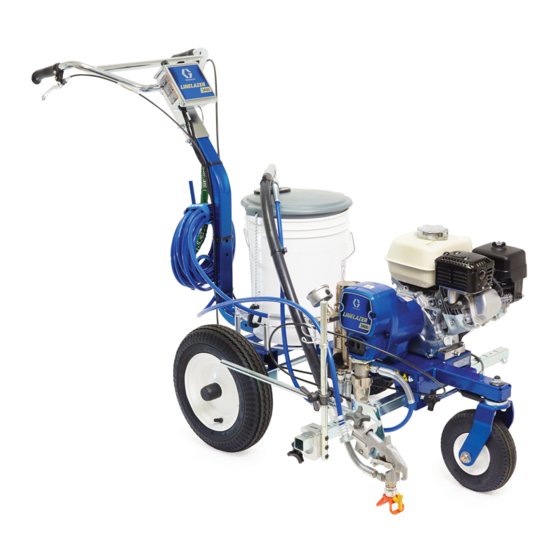
LineLazer
Airless Line Striper
- For the application of line striping materials. For professional use
only. Not for use in explosive atmospheres.-
Important Safety Instructions
Read all warnings and instructions in this
manual and in your gun manual. Save all
instructions.
Models: 248861, 249007, 24M609
3300 psi (22.8 MPa, 228 bar) Maximum Working Pressure
311016
309250
™
3400, FieldLazer S200
309741
309640
311019L
EN
ti24865a
Advertisement
Table of Contents

Related Manuals for Graco LineLazer 3400


Summary of Contents for Graco LineLazer 3400
- Page 1 Repair ™ LineLazer 3400, FieldLazer S200 311019L Airless Line Striper - For the application of line striping materials. For professional use only. Not for use in explosive atmospheres.- Important Safety Instructions Read all warnings and instructions in this manual and in your gun manual. Save all instructions.
-
Page 2: Table Of Contents
Pressure Control ......12 Graco Standard Warranty ....26 Displacement Pump . -
Page 3: Warning
• The LineLazer uses special, conductive tires for static grounding. No substitutions are allowed. Use only Graco-supplied replacement wheels and tires. • Do not fill fuel tank while engine is running or hot; shut off engine and let it cool. Fuel is flammable and can ignite or explode if spilled on hot surface. - Page 4 Check equipment daily. Repair or replace worn or damaged parts immediately. • Do not alter or modify equipment. • Use equipment only for its intended purpose. Call your Graco distributor for information. • Route hoses and cables away from traffic areas, sharp edges, moving parts, and hot surfaces. •...
-
Page 5: Maintenance
Maintenance Maintenance Pressure Relief Procedure DAILY: Check level of TSL in displacement pump packing nut. Fill nut, if necessary. Keep TSL in nut to help prevent fluid buildup on piston rod and premature wear of packings Follow the Pressure Relief Procedure whenever and pump corrosion.AFTER THE FIRST 20 HOURS OF you see this symbol. -
Page 6: Troubleshooting
At 70° F, the resistance must be between 1.2 +0.2; if not, replace pinion housing. Have pressure control checked by authorized Graco dealer Clutch is worn, damaged, or incor- Adjust or replace clutch. Page 9. rectly positioned Pinion assembly is worn or damaged Repair or replace pinion assembly. - Page 7 Troubleshooting Problem Cause Solution Pump output is low Strainer (56) is clogged Clean strainer. Piston ball (206) is not seating Service piston ball. Manual 309250. Piston packings are worn or damaged Replace packings. Manual 309250. O-ring (227) in pump is worn or damaged Replace o-ring. Manual 309250. Intake valve ball is not seating properly Clean intake valve.
-
Page 8: Drive Housing And Connecting Rod
Drive Housing and Connecting Rod Drive Housing and Connecting Rod Removal Install screws (34) in drive housing. Torque evenly to note 3 value in Fig. 1. Install pump. Refer to Displacement Pump, Installation, page 14 Install front cover (52) with two screws (32). Relieve pressure, page 5. -
Page 9: Pinion Assembly/Clutch Armature/Clamp
Pinion Assembly/Clutch Armature/Clamp Pinion Assembly/Clutch Armature/Clamp Pinion Assembly/Clutch Armature Removal Pinion Assembly If pinion assembly (44) is not removed from clutch housing (45), do 1. through 3. Otherwise, start at 4. Relieve pressure, page 5. Remove drive housing; page 8. . -
Page 10: Clamp Removal
Pinion Assembly/Clutch Armature/Clamp Installation Clutch Armature Install armature (39) on engine drive shaft. Install four screws (36) and lock washers (35) with torque . 8. Lay two stacks of two dimes on smooth bench of 125 in-lb. surface. Pinion Assembly Lay armature (39) on two stacks of dimes. -
Page 11: Clutch Housing
Clutch Housing Clutch Housing Removal Remove clamp. Do Clamp Removal, page 10. . 11. Remove four screws (51) and lock washers (50) which hold clutch housing (45) to engine. Remove screw (145) from under mounting plate. Pull off clutch housing (45). Installation . -
Page 12: Pressure Control
Pressure Control Pressure Control On/Off Switch Removal Installation Install new ON/OFF switch (62d) so tabs of switch snap into place on inside of cover. Connect ON/OFF switch connector (B) to PC board. Close cover (62a) and secure with two screws (108). Relieve pressure, page 5. -
Page 13: Control Board
Pressure Control Control Board Removal • Clutch wires Remove four screws (62f) and control board (62e). Installation . 14. Install control board (62e) with four screws (62f). Relieve pressure, page 5. Connect at control board (62e): . 14. Remove two screws (108) and open cover (62a) •... -
Page 14: Displacement Pump
Displacement Pump Displacement Pump Removal . 17. Loosen jam nut by hitting firmly with a hammer. Unscrew pump. Flush pump. Relieve pressure, page 5. . 16. Stop pump with piston rod (201) in its lowest position. . 15. Loosen two screws (32) and remove pump rod cover (107). - Page 15 . 18. Pull piston rod out distance shown. Screw in pump until holes in connecting rod and piston rod align. ti5544a . 19 ti5546a . 20. Fill packing nut with Graco TSL until fluid flows onto the top of seal. Install pump rod cover (107). ti5543a ti5546b . 18 .
- Page 16 Parts Drawing Parts Drawing 148 ref ti24872a ti6242c 311019L...
- Page 17 Parts List Parts List Ref. Ref. Part No. Description Part No. Description 15E955 HOLDER, bucket 287630 FRAME, LL 100057 SCREW, cap, hex hd 119542 WHEEL, small 113665 SCREW, cap, hex hd 119543 WHEEL, large 119554 NUT, lock, nylon, thin pattern 15F127 FORK, painted 248912 BAR, handle, LL 119532 BEARING, flanged...
-
Page 18: Parts Drawing
Parts Drawing Parts Drawing ti24873a 311019L... - Page 19 Parts Drawing Parts List Part No. Description Part No. Description 100214 WASHER, lock 246428 PUMP, displacement, st 108842 SCREW, cap, hex hd 196750 SPRING, retaining 287487 COVER, front, painted, includes 32 287053 ROD, connecting 246385 STRAINER, 7/8-14 unf 195150 NUT, jam, pump 287683 HOSE, suction, includes 33, 56, 196762 PIN, straight 130, 136...
- Page 20 Parts Drawing Parts Drawing and List - Pinion Housing Ref No. 44: Pinion Housing Part No. Description 287376 PINION HOUSING 287482 KIT, repair, coil 105489 PIN 44c* 287485 PINION SHAFT 44d* 113094 RETAINING RING, large * May be ordered separately ti5539a 311019L...
-
Page 21: Parts
Parts Drawing Gun Arm Parts ti6241a 18 Ref Part Description 287566 KIT, clamp Part Description 15F212 ARM, holder, gun 248157 GUN, Flex, basic 15F213 BRACKET, cable 287570 HOLDER, gun 15E992 CABLE, gun 287569 HOLDER, gun 119648 SCREW, mach, trusshd, cross recess 15F214 LEVER, actuator 224052 BRACKET, support gun 15F209 STUD, pull trigger... -
Page 22: Pressure Control/Filter Assembly
Pressure Control/Filter Assembly Pressure Control/Filter Assembly pink (from engine) ground (green/yellow) clutch (-) (black) clutch (+) 18 Ref (red) 155 Ref 118 Ref ti6239b 75 Ref ti6389a 106 Ref 311019L... -
Page 23: Pressure Control Wiring Diagram
Pressure Control/Filter Assembly Pressure Control/Filter Assembly Part Description 100* 15C972 PIN, grooved 101* 224807 BASE, valve Part Description 102* 239914 VALVE, drain 15E748 BRACKET, manifold 103* 117285 O-RING CONTROL, assy 104* 244067 FILTER, fluid 15E991 COVER, control box 105* 15C766 TUBE, diffusion 256219 POTENTIOMETER 196177 ADAPTER, nipple 116167 KNOB, potentiometer... -
Page 24: Technical Data
Technical Data Technical Data Honda GX120 Engine ANSI Power Rating @ 3600 rpm 4.0 Horsepower (2.9 kW) Maximum working pressure 3300 psi (227 bar, 22.7 MPa) Noise Level Sound power 100 dBa per ISO 3744 Sound pressure 86 dBa measured at 3.1 feet (1 m) Vibration Level * Left hand 3.89 m/sec... - Page 25 Notes Notes 311019L...
-
Page 26: Graco Standard Warranty
With the exception of any special, extended, or limited warranty published by Graco, Graco will, for a period of twelve months from the date of sale, repair or replace any part of the equipment determined by Graco to be defective.