Yamaha CD-S3000 Service Manual
Hide thumbs
Also See for CD-S3000:
- Owner's manual (242 pages) ,
- Safety manual (10 pages) ,
- Owner's manual (45 pages)
Table of Contents
Advertisement
CD-S3000
This manual has been provided for the use of authorized Yamaha Retailers and their service personnel.
It has been assumed that basic service procedures inherent to the industry, and more specifi cally Yamaha Products, are already known
and understood by the users, and have therefore not been restated.
WARNING:
IMPORTANT:
The data provided is believed to be accurate and applicable to the unit(s) indicated on the cover. The research, engineering, and service
departments of Yamaha are continually striving to improve Yamaha products. Modifi cations are, therefore, inevitable and specifi cations
are subject to change without notice or obligation to retrofi t. Should any discrepancy appear to exist, please contact the distributor's
Service Division.
WARNING:
IMPORTANT:
■ CONTENTS
TO SERVICE PERSONNEL ........................................2-4
FRONT PANELS .............................................................6
REAR PANELS ...........................................................7-9
REMOTE CONTROL PANEL ........................................ 10
SPECIFICATIONS / 参考仕様 ................................. 10-11
INTERNAL VIEW .......................................................... 12
SERVICE PRECAUTIONS / サービス時の注意事項 ..... 12
DISASSEMBLY PROCEDURES / 分解手順 ........... 13-24
UPDATING FIRMWARE /
ファームウェアのアップデート ............................25-30
ダイアグ(自己診断機能) .....................................31-41
1 0 1 2 7 3
COMPACT DISC PLAYER
SERVICE MANUAL
IMPORTANT NOTICE
Failure to follow appropriate service and safety procedures when servicing this product may result in personal injury,
destruction of expensive components, and failure of the product to perform as specifi ed. For these reasons, we advise
all Yamaha product owners that any service required should be performed by an authorized Yamaha Retailer or the
appointed service representative.
The presentation or sale of this manual to any individual or fi rm does not constitute authorization, certifi cation or
recognition of any applicable technical capabilities, or establish a principle-agent relationship of any form.
Static discharges can destroy expensive components. Discharge any static electricity your body may have
accumulated by grounding yourself to the ground buss in the unit (heavy gauge black wires connect to this buss).
Turn the unit OFF during disassembly and part replacement. Recheck all work before you apply power to the unit.
DISPLAY DATA .............................................................42
IC DATA ...................................................................43-46
BLOCK DIAGRAM ........................................................47
WIRING DIAGRAMS ...............................................48-49
PRINTED CIRCUIT BOARDS .................................50-59
PIN CONNECTION DIAGRAMS ...................................60
SCHEMATIC DIAGRAMS .......................................61-68
REPLACEMENT PARTS LIST ................................69-82
REMOTE CONTROL .....................................................83
パソコンに保存された音楽の再生 ...........................85-86
Copyright (c) Yamaha Corporation All rights reserved.
This manual is copyrighted by Yamaha and may not be copied or
redistributed either in print or electronically without permission.
P.O.Box 1, Hamamatsu, Japan
'13.10
Advertisement
Table of Contents

Related Manuals for Yamaha CD-S3000


Summary of Contents for Yamaha CD-S3000
-
Page 1: Table Of Contents
This manual has been provided for the use of authorized Yamaha Retailers and their service personnel. It has been assumed that basic service procedures inherent to the industry, and more specifi cally Yamaha Products, are already known and understood by the users, and have therefore not been restated. -
Page 2: To Service Personnel
CD-S3000 ■ TO SERVICE PERSONNEL AC LEAKAGE WALL EQUIPMENT TESTER OR 1. Critical Components Information OUTLET UNDER TEST EQUIVALENT Components having special characteristics are marked must be replaced with parts having specifications equal to those originally installed. 2. Leakage Current Measurement (For 120V Models Only) - Page 3 CD-S3000 WARNING: Laser Safety This product contains a laser beam component. This component may emit invisible, as well as visible radiation, which may cause eye damage. To protect your eyes and skin from laser radiation, the following precautions must be used during servicing of the unit.
- Page 4 CD-S3000 Warning for power supply The primary side of the power supply carries live mains voltage when the player is connected to the mains even when the player is switched off ! This primary area is not shielded so it is possible to accidentally touch copper tracks and/or components when servicing the player.
-
Page 5: Prevention Of Electrostatic Discharge
CD-S3000 ■ PREVENTION OF ELECTROSTATIC DISCHARGE Some semiconductor (solid state) devices can be damaged easily by static electricity. Such components commonly are called Electrostatically Sensitive (ES) Devices. Examples of typical ES devices are integrated circuits and some field-effect transistors and semiconductor “chip” components. The following techniques should be used to help reduce the incidence of component damage caused by electro static discharge (ESD). -
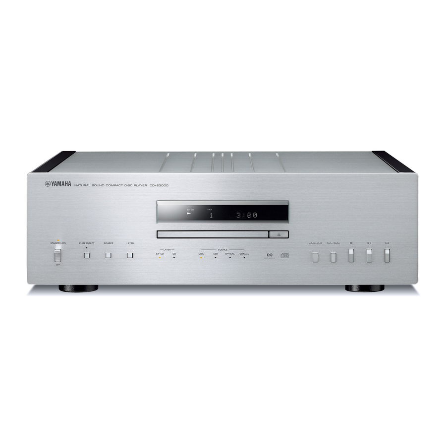
Page 6: Front Panels
CD-S3000 ■ FRONT PANELS U, K, A, B, G, L, V, J models T model... -
Page 7: Rear Panels
CD-S3000 ■ REAR PANELS U, V models Bottom view U model V model... - Page 8 CD-S3000 T model K model A, B, G, L models A model B, G models...
- Page 9 CD-S3000 J model...
-
Page 10: Remote Control Panel
CD-S3000 ■ REMOTE CONTROL PANEL ■ SPECIFICATIONS / 参考仕様 CDX30 ■ Audio Section / オーディオ部 Output Level / 出力レベル (1 kHz, 0 dB) SA-CD / CD ...............2.0 ±0.3 V Signal to Noise Ratio / 信号対雑音比 (IHF-A network) (1 kHz, 0 dB) SA-CD / CD .............. - Page 11 CD-S3000 Dimensions (W x H x D) / 寸法(幅 × 高さ × 奥行き) Accessories / 付属品 ....... 435 x 142 x 440 mm (17-1/8" x 5-5/8" x 17-3/8") Remote control ................x 1 Battery (R03, AAA, UM-4) .............x 2 Weight / 質量...
-
Page 12: Internal View
CD-S3000 ■ INTERNAL VIEW Top view FRONT (1) P.C.B. DIGITAL P.C.B. FRONT (2) P.C.B. AUDIO P.C.B. POWER TRANSFORMER for AUDIO FRONT (7) P.C.B. MODULE BOARD LOADER MECHANISM UNIT POWER TRANSFORMER for DIGITAL/FRONT FRONT (5) P.C.B. FRONT (3) P.C.B. FRONT (4) P.C.B. -
Page 13: Disassembly Procedures / 分解手順
CD-S3000 ■ DISASSEMBLY PROCEDURES / 分解手順 (Remove parts in the order as numbered.) (番号順に部品を外してください。 ) Disconnect the power cable from the AC outlet. AC 電源コンセントから、電源コードを抜いてください。 1. Removal of Top Panel 1. トップパネルの外し方 a. Remove 5 screws ( ① ). (Fig. 1) a. - Page 14 CD-S3000 3. Removal of Front Panel 3. フロントパネルの外し方 a. Using a flatblade screwdriver, move the slider at the a. マイナスドライバーで底面のスライダーを下図の矢印 bottom in the direction of the arrow shown below. の方向に動かします。 (Fig. 2) (Fig. 2) ※ このとき、ディスクトレイは押し出されません。 At this time, the disc tray is not pushed out.
- Page 15 CD-S3000 4. Removal of Front Frame Assembly 4. フロントフレーム Ass'y の外し方 a. Remove 8 screws ( ⑨ ). (Fig. 4) a. ⑨ のネジ 8 本を外します。 (Fig. 4) b. Remove CB908, CB910 and 8P connector. (Fig. 4) b. CB908、CB910、8P コネクターを外します。 (Fig. 4)...
- Page 16 CD-S3000 6. Removal of Loader Mechanism Unit 6. ローダーメカユニットの外し方 a. Remove 3 screws ( ⑭ ). (Fig. 6) a. ⑭ のネジ 3 本を外します。 (Fig. 6) b. Remove CB402, CB404 and CB407. (Fig. 6) b. CB402、CB404、CB407 を外します。 (Fig. 6) c. Remove the loader mechanism unit. (Fig. 6) c.
- Page 17 CD-S3000 ● When installing the Loader Mechanism Unit: ● ローダーメカユニットを取り付ける場合: When installing the loader mechanism unit, adjust its ローダーメカユニットを取り付ける場合には、フロン inclination so that the clearance between the front トパネルとリッドの隙間が上下左右同じになるように panel and lid becomes equal at the top, bottom, right ローダーメカユニットの傾きを調整してください。 and left.
- Page 18 CD-S3000 5. Turning screw ( ③ ), adjust the lid so that it becomes 5. 前面から見てリッドが水平になるように、③ のネ horizontal viewed from the front. (Fig. C) ジを回して調整します。 (Fig. C) To change the position upward, loosen screw ( ③ ) 位置を上方向に変更する場合は、③ のネジを右へ by turning it clockwise.
- Page 19 CD-S3000 7. Adjust the lid so that the clearance around the disc 7. 前面から見てディスクトレイの隙間が均一になる tray becomes equal viewed from the front. (Fig. E) ように、リッドを調整します。 (Fig. E) Front view “ ” (Open/Close) key “ ” (開閉)キー リ ッ ド Adjust the lid for equal clearance around it ディ...
- Page 20 CD-S3000 7. Removal of DIGITAL P.C.B. 7. DIGITAL P.C.B. の外し方 a. Remove 2 screws ( ⑮ ). (Fig. 7) a. ⑮ のネジ 2 本を外します。 (Fig. 7) b. Remove 7 screws ( ⑯ ) and screw ( ⑰ ). (Fig. 8) b.
- Page 21 CD-S3000 10. Removal of Power Transformer 10. 電源トランスの外し方 Remove 4 screws ( ). (Fig. 9) のネジ 4 本を外します。 (Fig. 9) b. Remove the power transformer for DIGITAL P.C.B. / DIGITAL P.C.B. / FRONT P.C.B. 用の電 源トラン スを、 FRONT P.C.B. together with the support. (Fig. 9) サポートと一緒に外します。...
- Page 22 CD-S3000 When checking the AUDIO P.C.B.: AUDIO P.C.B. をチェックをする場合には: • Put the rubber sheet and cloth over this unit. Then ・ 本機の上にゴムシートと布を敷き、その上に P.C.B. を place the P.C.B.s upside down on the cloth and check 裏返しに置いてチェックします。 (Fig. 10) it. (Fig. 10) ・...
- Page 23 CD-S3000 ● Disassembly of Loader Mechanism Unit ● ローダーメカユニットの分解手順 1. Removal of Module Board 1. モジュール基板の外し方 a. Solder the lands in the P.C.B. of the loader a. ローダーメカユニットの P.C.B. 上の端子間を静電 mechanism unit with the anti-static soldering iron. 気対策はんだこてを使用してショートします。 (Fig. 11) (Fig.
- Page 24 CD-S3000 2. Removal of Loading Belt 2. ローディングベルトの外し方 a. Remove 6 screws ( ) and then remove the clamp のネジ 6 本を外し、クランプ Ass'y を外します。 assembly. (Fig. 12) (Fig. 12) b. Push out the disc tray by pushing its rear. (Fig. 12) b.
-
Page 25: ファームウェアのアップデート
CD-S3000 ■ UPDATING FIRMWARE / ファームウェアのアップデート When the following parts are replaced, the firmware must 下記の部品を交換した場合、ファームウェアを最新バー be updated to the latest version. ジョンにアップデートする必要があります。 DIGITAL P.C.B. DIGITAL P.C.B. Main microprocessor: IC404 on DIGITAL P.C.B. メインマイコン:DIGITAL P.C.B. の IC404 ● Confirmation of firmware version and checksum ●... - Page 26 CD-S3000 3. Press the “ ” (Open/Close) key to close the disc (開閉)キーを押してディスクトレイを閉じ、 tray and check that “NO DISC” appears on the ディスプレイへ NO DISC が表示されることを display. 確認します。 4. Press the “ ” (Stop) key for 2 seconds or longer (停止)キーを...
- Page 27 CD-S3000 ● Connection ● 接続 Disconnect the power cable of this unit from the ※ 本機の電源コードを AC コンセントから抜きます。 AC outlet. ・ RS-232C 変換アダプターのスイッチを下記のよう • Set the switches on RS-232C conversion adaptor に設定します。 (Fig. 1) as shown below. (Fig. 1) DSP ucom T...
- Page 28 CD-S3000 ● Operation procedures ● 操作方法 1. Set the “STANDBY/ON / OFF” (Power) (U, K, A, B, STANDBY/ON / OFF (電源)スイッチを ON G, L, V models) / “ ” (Power) (T model) switch to にします。 the “ON” position. 2. 本機の電源コードを AC コンセントに接続します。...
- Page 29 CD-S3000 5. Click [Refer...] and select the firmware name. 5. [Refer...]をクリックし、書き込むファームウェア (Fig. 4) を選択します。 (Fig. 4) The ID and MCU Type are loaded automatically ※ ID、および MCU Type は書き込みファイル選 when the file is selected. (Fig. 4) 択後、自動的に取り込まれます。 (Fig. 4) Click [OK]. (Fig. 4) [OK]をクリックします。...
- Page 30 CD-S3000 7. Click [E.P.R.], then the “Erase” screen appears. 7. [E.P.R]をクリックすると、 「Erase」が表示されま (Fig. 6) す。 (Fig. 6) 8. Click [OK] to start writing. (Fig. 6) 8. [OK]をクリックして書き込みを開始します。 (Fig. 6) Writing being executed. 書き込み中 Fig. 6 9. When writing of the firmware is completed, the 9.
-
Page 31: Self-Diagnostic Function / ダイアグ(自己診断機能
CD-S3000 ■ SELF-DIAGNOSTIC FUNCTION / ダイアグ(自己診断機能) This unit has self-diagnostic functions that are intended 本機には、検査、測定、不良個所の発見を目的にしたダ for inspection, measurement and location of faulty point. イアグ(自己診断機能)があります。 There are 9 main menu items, each of which has sub- ダイアグには 9 個のメインメニューがあり、そのそれぞ menu items. - Page 32 CD-S3000 ● Starting Self-Diagnostic Function ● ダイアグの起動 While pressing the “ ” (Stop), “ ” (Play) and “PURE (停止)と (再生) 、 PURE DIRECT キーを押し DIRECT” keys simultaneously, set the “STANDBY/ON / ながら、 STANDBY/ON / OFF (電源)スイッチを ON OFF” (Power) (U, K, A, B, G, L, V models) / “ ” (Power) (T にして電源を入れた後、3 つのキーを放します。...
- Page 33 CD-S3000 ● History of protection function ● プロテクションの履歴 When the protection function has worked, its history プロテクションが働いた場合、 その履歴はバックアッ is stored in memory as backup data. プデータとしてメモリーに保存されます。 Even if no abnormality is noted while servicing the 修理のときに異常が認められなくても、バックアッ unit, an abnormality which has occurred previously プデータが残っていれば、お客様のところで起きた...
- Page 34 CD-S3000 ● Operation procedure of Main menu ● メインメニューとサブメニューの操作 and Sub-menu There are 9 main menu items, each of which has sub- ダイアグには 9 個のメインメニューがあり、そのそれぞ menu items. れにサブメニューがあります。 Main menu and Sub-menu selection メインメニューとサブメニューの選択 Select the main menu using “...
- Page 35 CD-S3000 ● Details of Self-Diagnostic Function menu ● ダイアグメニュー詳細 1. ROM VERSION/CHECKSUM 1. ROM VERSION/CHECKSUM This menu is used to display the firmware version and ファームウェアバージョン、チェックサムが表示さ checksum. れます。 The checksum is obtained by adding the data at every チェックサムは、データを 8 ビットごとに加算して...
- Page 36 CD-S3000 2. FRONT PANEL KEY CHECK 2. FRONT PANEL KEY CHECK This menu is used to check operation of the panel パネルキーの動作をチェックします。 keys. 2-1. PANEL KEY CHECK MENU 2-1. PANEL KEY CHECK MENU “PANEL KEY CHECK” menu is displayed. PANEL KEY CHECK メニューが表示されます。...
- Page 37 CD-S3000 3. FL DISPLAY CHECK 3. FL DISPLAY CHECK This menu is used to check operation of the FL FL 表示とインジケーターの動作をチェックします。 display and indicator. 3-1. FL DISPLAY MENU 3 - 1 . D I S P C H K Initial display 初期表示...
- Page 38 CD-S3000 4. FACTORY PRESET 4. FACTORY PRESET This menu is used to initialization of the back-up data. バックアップデータの初期化をします。 4-1. FACTORY PRESET MENU 4 - 1 . F _ P ? Initial display Press the “LAYER” key. 初期表示 LAYER キーを押します。 4-1. PRESET RESERVED (Initialization reserved) / PRESET RESERVED(初期化予約)...
- Page 39 CD-S3000 5-2. PRV_R 5-2. PRV_R R channel power supply protection detection R チャンネルの電源電圧プロテクションの検出 Detected: +12VR, -12VR, +5VR, +3.3VR, 検出先: +12VR、-12VR、+5VR、+3.3VR、 AC_R AC_R Detection port: 81 pin of main microprocessor 検出ポート: メインマイコン(DIGITAL P.C.B. の (IC404 on DIGITAL P.C.B.) IC404)の 81 ピン...
- Page 40 CD-S3000 6. PROTECTION HISTORY 6. PROTECTION HISTORY This menu is used to display the history of protection プロテクション履歴が表示されます。 function. 6-1. HISTORY 1 to HISTORY 4 6-1. HISTORY 1 ∼ HISTORY 4 The display is changed by pressing the “LAYER” LAYER キーを押すと表示が切り替わります。...
- Page 41 CD-S3000 9. TRAY CHECK 9. TRAY CHECK This menu is used to check the loader mechanism ローダーメカユニットの動作チェックをします。 unit. 9-1. CLAMP DOWN/TRAY OPEN CHECK 9-1. CLAMP DOWN/TRAY OPEN CHECK Check that the CLAMP moves down and the クランプが下がり、ディスクトレイが開くこと disc tray opens.
-
Page 42: Display Data
CD-S3000 ■ DISPLAY DATA ● V901 : 013ST087GINK (FRONT (3) P.C.B.) ● PIN CONNECTION Pin No. Connection Q13G Pin No. Connection RESET Pin No. Connection LGND PGND Note: 1) F1, F2 ..Filament 2) NP ..No pin 3) NX ..No extended pin 4) LGND .. -
Page 43: Ic Data
CD-S3000 ■ IC DATA IC404: R5F364AENFA (DIGITAL P.C.B.) Microprocessor * No replacement part available. / サービス部品供給なし Port P0 Port P1 Port P1 Port P3 Port P4 Port P5 VCC2 ports Internal peripheral functions System clock generator UART or clock synchronous serial I/O... - Page 44 CD-S3000 Function Name Port Name Detail of Function (P.C.B.) P9_6/ANEX1/SOUT4 FL_EX_MOSI FL Driver control data output Extended IC: Data out for LC709004A P9_5/ANEX0/CLK4 FL__EX_CLK FL Driver control clock output Extended IC: Clock for LC709004A P9_4/DA1/TB4IN/PWM1 PULSE_DET Pulse input for tray driving motor...
- Page 45 CD-S3000 Function Name Port Name Detail of Function (P.C.B.) 34 P6_4/nCTS1/nRTS1/nCTS0/ WR_BUSY [MCU] For simple emulation / BUSY output when writing flash CLKS1 35 P6_3/TXD0/SDA0 DAC_SDA DAC ESS9018S control I2C data input/output / I2C fs=100k/400k 36 P6_2/RXD0/SCL0 DAC_SCL DAC ESS9018S control I2C data output / I2C fs=100k/400k...
- Page 46 CD-S3000 Function Name Port Name Detail of Function (P.C.B.) 66 P2_6/AN2_6/A6 PWR_RY Power relay control 67 P2_5/INT7/AN2_5/A5 ACPWR_DET AC power input detection 68 P2_4/INT6/AN2_4/A4 CD_PWR_DET Vaddis886 SDRAM CLOCK enable control monitor 69 P2_3/AN2_3/A3 SW_CD_OTHER For switching control between CD and other functions...
-
Page 47: Block Diagram
CD-S3000 ■ BLOCK DIAGRAM +12L +3.3L DAC 3.3V Shunt Loader mechanism unit +1.2L DAC 1.2V +5MO1 AGNDL Y101 +5MO2 Shunt 27Hz +7MT SA-CD -12L Module CD_SPDIF_RQ CD_PWR_DET DAC1 CD_RST DAC3 CD_PWR DAC5 CD_MUTE DAC7 CD_YOVI CD_YIVO IV Convertor DOUT 40MHz... -
Page 48: Wiring Diagrams
CD-S3000 ■ WIRING DIAGRAMS • OVERALL ASSEMBLY Top view Bottom view AC IN FRONT (2) CB902 CB410 W901 DIGITAL W903 FRONT (1) to FRONT (3) to DIGITAL (CB406) to Module board (CB910) AUDIO CB408 (CN211) to Module board CB406 (CN210) - Page 49 CD-S3000 • LOADER MECHANISM UNIT Top view to DIGITAL (CB402) to DIGITAL (CB407) Flexible flat cable to DIGITAL (CB407) Letter side 50 mm 10 mm (3/8") (2") to Module board (CN210) Letter side Flexible flat cable CN211 CN210 CN205 CN201...
-
Page 50: Printed Circuit Boards
CD-S3000 ■ PRINTED CIRCUIT BOARDS FRONT (3) (CB910) Module board DIGITAL (Side A) (CN211) Module board (CN210) CB404 CB407 CB402 CB405 Loader mechanism unit • Semiconductor Location Ref no. Location IC419 D401 D402 CB406 SEL_SDO_DSDR D405 DGND SEL_SDO_DSDL DGND D407... - Page 51 CD-S3000 DIGITAL (Side B) • Semiconductor Location Ref no. Location D406 D408 D410...
- Page 52 CD-S3000 • Semiconductor Location Safety measures Ref no. Location Ref no. Location Ref no. Location Ref no. Location Ref no. Location Ref no. Location • Some internal parts in this product contain high voltages and are dangerous. Be sure to take safety measures during servicing, such as wearing insulating gloves.
- Page 53 CD-S3000 • Semiconductor Location Ref no. Location Ref no. Location Ref no. Location Ref no. Location Ref no. Location Ref no. Location Ref no. Location Ref no. Location D307 Q309 Q319 D308 Q310 Q320 D309 Q311 Q321 D310 Q312 Q322...
- Page 54 CD-S3000 FRONT (1) (Side A) DIGITAL (CB410) 5 k-ohms 5 k-ohms 10 W 10 W CB902 to POWER TRANSFORMER (for DIGITAL/FRONT P.C.B.) IC905 IC909 to POWER TRANSFORMER (for DIGITAL/FRONT P.C.B.) W902 • Semiconductor Location Ref no. Location 5 k-ohms 5 k-ohms...
- Page 55 CD-S3000 FRONT (1) (Side B) CB902 IC905 IC909 • Semiconductor Location Ref no. Location D902 D904 D905 D907 D909 D914 D915 D916 D917 D918 D957 W902 D958 Q903...
- Page 56 CD-S3000 Safety measures 安全対策 • Some internal parts in this product contain high voltages and are dangerous. Be sure to take safety measures during servicing, such ・ この製品の内部には高電圧部分があり危険です。修理の際は、絶縁性の手袋を使用するなどの安全対策を行ってください。 as wearing insulating gloves. ・ 下記のコンデンサには電源を OFF にした後も電荷が残り、高電圧が維持されており危険です。修理作業前に放電用抵抗 • Note that the capacitors indicated below are dangerous even after the power is turned off because an electric charge remains and a (5 k Ω...
- Page 57 CD-S3000 FRONT (2) (Side B) IC909 • Semiconductor Location Ref no. Location D921 D922 D924 D925 D926 D928 D929 D931 D932 D933 D934 D935 D937 D959 D960 D961 D962 FRONT (6) FRONT (7-1) FRONT (7-2) (Side B) (Side B) (Side B)
- Page 58 CD-S3000 • Semiconductor Location Ref no. Location Ref no. Location D945 D951 D946 D952 D953 D947 D950 D956 FRONT (3) (Side A) Remote control sensor DIGITAL (CB405) IC910 S3 UNCLAMP TRAY_SW S1 TRAY CLOSE S4 CLAMP +3.3M MGND CLAMP MOTOR+...
- Page 59 CD-S3000 FRONT (3) (Side B) IC910 • Semiconductor Location Ref no. Location Ref no. Location D938 D949 D939 D954 D940 D955 D941 IC910 D942 IC911 D943 Q911 D944 Q912 D948 Q913 FRONT (4) FRONT (5) (Side B) (Side B) IC911...
-
Page 60: Pin Connection Diagrams
CD-S3000 ■ PIN CONNECTION DIAGRAMS • ICs • Diodes BA05CC0T BA6956AN BD00GA3WEFJ-E2 EN29LV160CB-70TIP ES9018 1SR154-400 1SS355VMTE-17 D4SBN20-7101 RS203M-B-C-J80 S1NB60 1.0A 600V UDZV2.0B UDZV11B BA07CC0T UDZV3.3B UDZV12B UDZV3.6B UDZV30B UDZV4.7B Anode UDZV5.1B Anode UDZV5.6B Anode – – – Cathode Cathode Cathode... -
Page 61: Schematic Diagrams
CD-S3000 SCHEMATIC DIAGRAMS DIGITAL 1/3 D I G I T A L 0 0 1 . s h t D e s t i n a t i o n P a r t L i s t + 1 2 R Y... - Page 62 CD-S3000 DIGITAL 2/3 N O T I C E ( m o d e l ) J A P A N U . S . A C A N A D A G E N E R A L C H I N A...
- Page 63 CD-S3000 DIGITAL 3/3 M e m o r y I / F M A I N A - B u s I / F P u w e r S u p p l y J 4 1 0 J 4 1 1...
- Page 64 CD-S3000 IC2, 6, 7: R1172S121D-E2-F IC1: TC74VHC541FT AUDIO 1/2 Voltage regulator Octal bus buffer Vref Current Limit C 9 5 C 1 0 9 R 8 6 R 9 0 2 . 2 C 9 0 . 0 1 / 1 6 ( B )
- Page 65 CD-S3000 AUDIO 2/2 A U D I O 0 0 2 . s h t 4 0 0 N O T I C E ( m o d e l ) J A P A N R 3 0 5 R 3 3 3 U .
- Page 66 CD-S3000 FRONT 1/3 S A N - P H W 9 0 2 F R O N T FRONT (1) 29.9 + V P 9 0 1 1 0 0 8 Page 68 F L G N D to FRONT (3)_CB908...
- Page 67 CD-S3000 FRONT 2/3 J K 9 0 3 FRONT (2) J Y - 5 0 4 0 - 0 4 0 F R O N T Q 9 0 6 2 0 0 2 0 0 A 1 0 3 7 A K ( Q / R / S )
- Page 68 CD-S3000 FRONT 3/3 FRONT (3) F R O N T ( 3 ) F R O N T C B 9 0 8 P H L 9 0 1 1 0 0 0 29.9 + V P F L G N D...
-
Page 69: Replacement Parts List
CD-S3000 ■ REPLACEMENT PARTS LIST • ELECTRICAL COMPONENT PARTS WARNING ● Components having special characteristics are marked and must be replaced with parts having specifications equal to those originally installed. ● 印のある部分は、安全確保部品を示しています。部品の交換が必要な場合、パーツリストに記載されている部品を使用し てください。 ● 部品価格ランクは、予告なく変更することがあります。 ABBREVIATIONS IN THIS LIST ARE AS FOLLOWS: C.A.EL.CHP... - Page 70 CD-S3000 DIGITAL Ref No. Part No. Description Remarks Markets 部 品 名 ランク ZF862300 P.C.B. DIGITAL PCB DIGITAL ZF862400 P.C.B. DIGITAL UTKALV PCB DIGITAL ZF862500 P.C.B. DIGITAL PCB DIGITAL ZF862600 P.C.B. DIGITAL PCB DIGITAL CB402 WK469100 CN.FMN FMN 29P TE FMNコネクター CB403 VQ047200 CN.BS.PIN コネクター CB404 VB389800 CN.BS.PIN...
- Page 71 CD-S3000 DIGITAL Ref No. Part No. Description Remarks Markets 部 品 名 ランク C466 US064100 C.CE.CHP 0.01uF 50V B チップセラコン C467-468 US062100 C.CE.CHP 100pF 50V B チップセラコン C469 US035100 C.CE.CHP 0.1uF 16V B チップセラコン C470 US061100 C.CE.CHP 10pF 50V B チップセラコン C471 US064100 C.CE.CHP...
- Page 72 CD-S3000 DIGITAL Ref No. Part No. Description Remarks Markets 部 品 名 ランク C552 US135100 C.CE.CHP 0.1uF チップセラコン C555-556 US063470 C.CE.CHP 4700pF 50V B チップセラコン C571-572 US063100 C.CE.CHP 1000pF 50V B チップセラコン C580 UR237330 C.EL 33uF ケミコン C581 UR238100 C.EL 100uF JUTKALV ケミコン...
- Page 73 CD-S3000 DIGITAL and AUDIO Ref No. Part No. Description Remarks Markets 部 品 名 ランク IC424 YC213A00 IC PCM9210PTR IC IC430 X8897A00 IC R1172S331B-E2-F 電源IC IC438 X5482A00 IC NE5532DR OP AMP アンプIC * IC441 X9293A00 IC R1172H151D-T1-FE 電源IC * JK401 V7808900 CN.USB UBB 4P SE USBジャック...
- Page 74 CD-S3000 AUDIO Ref No. Part No. Description Remarks Markets 部 品 名 ランク C89-90 WE102100 C.PP 2200pF 100V J PPコン C95-96 US064100 C.CE.CHP 0.01uF 50V B チップセラコン C101-102 WE101700 C.PP 1000pF 100V J PPコン C107-108 WE102100 C.PP 2200pF 100V J PPコン C109-110 US064100 C.CE.CHP...
- Page 75 CD-S3000 AUDIO Ref No. Part No. Description Remarks Markets 部 品 名 ランク VV556400 TR 2SC2412K Q,R,S トランジスタ WW781800 TR.DGT DTA014EUBTL デジタルトランジスタ V7421800 TR 2SA1312-GR,BL トランジスタ V7421700 TR.CHP 2SC3324-GR,BL チップトランジスタ V7421800 TR 2SA1312-GR,BL トランジスタ V7421700 TR.CHP 2SC3324-GR,BL チップトランジスタ V7421800 TR 2SA1312-GR,BL トランジスタ...
- Page 76 CD-S3000 AUDIO and FRONT Ref No. Part No. Description Remarks Markets 部 品 名 ランク R120-123 WQ835800 R.MTL.OXD 100Ω 酸化金属被膜抵抗 R124-129 Vi192500 R.MTL.CHP 100Ω 1/10W チップ金属被膜抵抗 * R130-133 ZG861700 R.MTL.OXD 200Ω 酸化金属被膜抵抗 R142-147 Vi199000 R.MTL.CHP 47KΩ 1/10W チップ金属被膜抵抗 R148-159 Vi193300 R.MTL.CHP 220Ω...
- Page 77 CD-S3000 FRONT Ref No. Part No. Description Remarks Markets 部 品 名 ランク C944 WE102900 C.PP 0.01uF 100V J PPコン C945 V6185300 C.CE.SAFTY 0.01uF 275V 規格認定コンデンサ C946-947 UU237100 C.EL 10uF ケミコン C949 UU238100 C.EL 100uF ケミコン C950 US063100 C.CE.CHP 1000pF 50V B チップセラコン...
- Page 78 CD-S3000 FRONT Ref No. Part No. Description Remarks Markets 部 品 名 ランク D961-963 VT532500 DIODE 1SR154-400 ダイオード F901 WG409800 FUSE 125V ヒューズ F901 KB000750 FUSE.MINI 250V TKABGL ミニヒューズ * IC901-903 YF323A00 IC BA05CC0T 5V 電源IC * IC904 YF429A00 IC BA07CC0T 7V 電源IC...
- Page 79 CD-S3000 Carbon Resistors Value 1/4W Type Part No. 1/6W Type Part No. Value 1/4W Type Part No. 1/6W Type Part No. 1.0 Ω HJ35 3100 HF85 3100 11 kΩ HF45 7110 HF45 7110 ✻ 1.8 Ω 3180 12 kΩ 7120...
- Page 80 CD-S3000 1 (1) • OVERALL ASSEMBLY Loader mechanism unit 1 (5) 4-22 4-22 1 (6) 4-18 4-22 4-32 4-15 4-41 4-34 4-33 4-34 4-13 1 (3) 1 (4) 4-14 4-16 4-11 4-13 4-13 300-1 4-16...
- Page 81 CD-S3000 Ref No. Part No. Description Remarks Markets 部 品 名 ランク Ref No. Part No. Description Remarks Markets 部 品 名 ランク ZF861000 P.C.B. ASSEMBLY FRONT PCB FRONT * 18 YF337A00 POWER TRANSFORMER for DIGITAL/FRONT PCB 電源トランス ZF861100 P.C.B. ASSEMBLY FRONT PCB FRONT * 18...
- Page 82 CD-S3000 • LOADER MECHANISM UNIT Ref No. Part No. Description Remarks Markets 部 品 名 ランク 5-32 5-33 ZF861000 P.C.B. ASSEMBLY FRONT PCB FRONT ZF861100 P.C.B. ASSEMBLY FRONT PCB FRONT ZF861200 P.C.B. ASSEMBLY FRONT TKAL PCB FRONT 5-20 ZF861300 P.C.B. ASSEMBLY FRONT PCB FRONT ZF861400 P.C.B. ASSEMBLY FRONT PCB FRONT...
-
Page 83: Remote Control
CD-S3000 ■ REMOTE CONTROL SCHEMATIC DIAGRAM PANEL KEY NO. LAYOUT KEY CODE Mode-1 Option Key Name Customer Data code code 10 ohms 2AD4 5.1K ohms OPEN/CLOSE SOURCE DIMMER REPEAT 22K ohms 22K ohms M34286G2GP 47 uF 1 ohm 1/4W OPEN/... -
Page 84: Playback Of Music Files Stored On A Pc
CD-S3000 ■ PLAYBACK OF MUSIC FILES STORED ON A PC Rear panel of CD-S3000 OPTICAL COAXIAL BALANCED OUT DIGITAL IN USB cable (Type B) -
Page 85: パソコンに保存された音楽の再生
CD-S3000 ■ パソコンに保存された音楽の再生 CD-S3000 リアパネル OPTICAL COAXIAL BALANCED OUT DIGITAL IN USB ケーブル(Type B) パソコン... - Page 86 CD-S3000...
- Page 87 CD-S3000 MEMO...
- Page 88 CD-S3000...