Advertisement
QQ
3 7 63 1515 0
S
ervice
M anua l
BRIDGEABLE FOUR-CHANNEL POWER AMPLIFIER
GM-X424
GM-X324
CONTENTS
1. SAFETY INFORMATION ............................................1
2. EXPLODED VIEWS AND PARTS LIST .......................2
3. SCHEMATIC DIAGRAM .............................................6
TE
L 13942296513
4. PCB CONNECTION DIAGRAM ..................................8
1. SAFETY INFORMATION
This service manual is intended for qualified service technicians; it is not meant for the casual do-it-yourselfer.
Qualified technicians have the necessary test equipment and tools, and have been trained to properly and safely repair
complex products such as those covered by this manual.
Improperly performed repairs can adversely affect the safety and reliability of the product and may void the warranty.
If you are not qualified to perform the repair of this product properly and safely, you should mot risk trying to do so
and refer the repair to a qualified service technician.
UC model
CAUTION
This service manual is intended for qualified service technicians; it is not meant for the casual do-it-yourselfer.
Qualified technicians have the necessary test equipment and tools, and have been trained to properly and safely repair
complex products such as those covered by this manual.
Improperly performed repairs can adversely affect the safety and reliability of the product and may void the warranty.
If you are not qualified to perform the repair of this product properly and safely; you should not risk trying to do so
and refer the repair to a qualified service technician.
WARNING
Lead in solder used in this product is listed by the California Health and Welfare agency as a known reproductive toxi-
www
cant which may cause birth defects or other reproductive harm (California Health & Safety Code, Section 25249.5).
When servicing or handling circuit boards and other components which contain lead in solder, avoid unprotected skin
contact with the solder. Also, when soldering do not inhale any smoke or fumes produced.
.
PIONEER ELECTRONIC CORPORATION
PIONEER ELECTRONICS SERVICE INC.
PIONEER ELECTRONIC [EUROPE] N.V.
PIONEER ELECTRONICS ASIACENTRE, PTE.LTD. 501 Orchard Road, #10-00, Wheelock Place, Singapore 238880
C PIONEER ELECTRONIC CORPORATION 1998
http://www.xiaoyu163.com
x
ao
u163
y
i
P.O.Box 1760, Long Beach, CA 90801-1760 U.S.A.
Haven 1087 Keetberglaan 1, 9120 Melsele, Belgium
http://www.xiaoyu163.com
2 9
8
X1R/UC
5. ELECTRICAL PARTS LIST ........................................12
6. ADJUSTMENT..........................................................16
7. GENERAL INFORMATION .......................................16
3
6 7
1 3
1 5
7.1 DISASSEMBLY ...................................................16
8. OPERATIONS AND SPECIFICATIONS.....................17
co
.
4-1, Meguro 1-Chome, Meguro-ku, Tokyo 153-8654, Japan
9 4
2 8
ORDER NO.
CRT2168
X1R/UC, ES, EW
0 5
8
2 9
9 4
2 8
m
K-ZEU. JAN. 1998 Printed in Japan
9 9
9 9
Advertisement
Table of Contents

Related Manuals for Pioneer GM-X424 X1R/UC


Summary of Contents for Pioneer GM-X424 X1R/UC
-
Page 1: Table Of Contents
P.O.Box 1760, Long Beach, CA 90801-1760 U.S.A. PIONEER ELECTRONIC [EUROPE] N.V. Haven 1087 Keetberglaan 1, 9120 Melsele, Belgium PIONEER ELECTRONICS ASIACENTRE, PTE.LTD. 501 Orchard Road, #10-00, Wheelock Place, Singapore 238880 C PIONEER ELECTRONIC CORPORATION 1998 K-ZEU. JAN. 1998 Printed in Japan... -
Page 2: Exploded Views And Parts List
http://www.xiaoyu163.com GM-X424, GM-X324 3 7 63 1515 0 2. EXPLODED VIEWS AND PARTS LIST 2.1 PACKING L 13942296513 Fig. 1 NOTE: Parts marked by “*”are generally unavailable because they are not in our Master Spare Parts List. Screws adjacent to ∇ mark on the product are used for disassembly. (1) PACKING SECTION PARTS LIST Mark No. - Page 3 http://www.xiaoyu163.com GM-X424, GM-X324 3 7 63 1515 0 (2) CONTRAST TABLE GM-X424/X1R/UC, GM-X424/X1R/ES, GM-X424/X1R/EW and GM-X324/X1R/UC are constructed the same except for the following: Part No. GM-X424 GM-X324 Mark No. Symbol and Description X1R/UC X1R/ES X1R/EW X1R/UC Contain Box HHL0142 HHL0143 HHL0144 HHL0141...
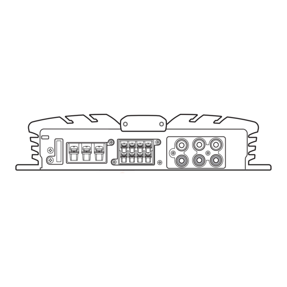
- Page 4 http://www.xiaoyu163.com GM-X424, GM-X324 3 7 63 1515 0 2.2 EXTERIOR L 13942296513 u163 Fig. 2 http://www.xiaoyu163.com...
- Page 5 http://www.xiaoyu163.com GM-X424, GM-X324 3 7 63 1515 0 (1) EXTERIOR SECTION PARTS LIST Mark No. Description Part No. Mark No. Description Part No. 1 Screw BSZ30P050FZK 26 Clamper HNV0003 2 Screw(M3x6) CBA1320 27 Holder HNV0005 3 Screw(M3x12) CBA1323 28 Pin Jack(CN852) See Contrast table (2) 4 Screw CBA1382...
-
Page 6: Schematic Diagram
http://www.xiaoyu163.com GM-X424, GM-X324 3 7 63 1515 0 3. SCHEMATIC DIAGRAM Note: When ordering service parts, be sure to refer to "EXPLODED VIEWS AND PARTS LIST" or "ELECTRICAL PARTS LIST". THRU-PUT MOTHER PCB LPF / HPF R179, 180 : GM-X324 only BASS VR153 : GM-X424 only ISOLATOR PCB... - Page 7 http://www.xiaoyu163.com GM-X424, GM-X324 3 7 63 1515 0 PRE DRIVER POWER AMP BASS BOOST OVER CURRENT DETECTOR BUFFER AMP OVER VOLTAGE DETECTOR 4R7/50 4R7/50 L 13942296513 FLAT AMP POWER MUTE DETECTOR MUTE FLAT AMP OVER CURRENT PROTECTOR & OVER POWER CONTROL / MUTE VOLTAGE PROTECTOR ES and EW...
-
Page 8: Pcb Connection Diagram
http://www.xiaoyu163.com GM-X424, GM-X324 3 7 63 1515 0 4. PCB CONNECTION DIAGRAM NOTE FOR PCB DIAGRAMS 1. The parts mounted on this PCB 2. Viewpoint of PCB diagrams include all necessary parts for Capacitor Connector several destination. SIDE A For further information for respective destinations, be sure to check with the schematic dia- SIDE B... - Page 9 http://www.xiaoyu163.com GM-X424, GM-X324 3 7 63 1515 0 SIDE A CN601 CORD ASSY L 13942296513 CN861, CN862 u163 Fig. 4 http://www.xiaoyu163.com...
- Page 10 http://www.xiaoyu163.com GM-X424, GM-X324 3 7 63 1515 0 MOTHER PCB L 13942296513 u163 http://www.xiaoyu163.com...
- Page 11 http://www.xiaoyu163.com GM-X424, GM-X324 3 7 63 1515 0 SIDE B ISOLATOR PCB L 13942296513 u163 Fig. 5 http://www.xiaoyu163.com...
-
Page 12: Electrical Parts List
http://www.xiaoyu163.com GM-X424, GM-X324 3 7 63 1515 0 5. ELECTRICAL PARTS LIST NOTE: - Parts whose parts numbers are omitted are subject to being not supplied. - The part numbers shown below indicate chip components. Chip Resistor RS1/_S___J,RS1/__S___J Chip Capacitor (except for CQS..) CKS.., CCS.., CSZS.. - Page 13 http://www.xiaoyu163.com GM-X424, GM-X324 3 7 63 1515 0 =====Circuit Symbol and No.===Part Name Part No. =====Circuit Symbol and No.===Part Name Part No. ------ --------------------------------------------- ------------------------- ------ --------------------------------------------- ------------------------- Switch CSH1029 RS1/10S222J Switch CSH1021 RS1/10S222J Switch CSH1021 RS1/10S222J Volume 10kΩ(C) CCS1240 RS1/10S222J Volume 50kΩ(C) CCS1242...
- Page 14 http://www.xiaoyu163.com GM-X424, GM-X324 3 7 63 1515 0 =====Circuit Symbol and No.===Part Name Part No. =====Circuit Symbol and No.===Part Name Part No. ------ --------------------------------------------- ------------------------- ------ --------------------------------------------- ------------------------- 0.22Ω CCN1013 RN1/10SE1002D 0.22Ω CCN1013 RN1/10SE1002D 0.22Ω CCN1013 RN1/10SE1002D 0.22Ω CCN1013 RN1/10SE1002D 0.22Ω...
-
Page 15: Amp Unit
http://www.xiaoyu163.com GM-X424, GM-X324 3 7 63 1515 0 =====Circuit Symbol and No.===Part Name Part No. =====Circuit Symbol and No.===Part Name Part No. ------ --------------------------------------------- ------------------------- ------ --------------------------------------------- ------------------------- CKSQYB473K25 CEAS221M10 CKSQYB473K25 CEAS2R2M50 CEAS471M10 CQMA102J50 CEAS471M10 CEAS1R0M50 CEAS471M10 CEAS470M16 CEAS471M10 3300µF/16V CCH1130 CCSQCH330J50 3300µF/16V... -
Page 16: Adjustment
http://www.xiaoyu163.com GM-X424, GM-X324 3 7 63 1515 0 6. ADJUSTMENT There is no information to be shown in this chapter. 7. GENERAL INFORMATION 7.1 DISASSEMBLY - Removing the Case and Panel 1. Remove six screws A, and then remove case. 2. -
Page 17: Operations And Specifications
http://www.xiaoyu163.com GM-X424, GM-X324 3 7 63 1515 0 8. OPERATIONS AND SPECIFICATIONS - SETTING THE UNIT L 13942296513 u163 http://www.xiaoyu163.com... - Page 18 http://www.xiaoyu163.com GM-X424, GM-X324 3 7 63 1515 0 L 13942296513 u163 http://www.xiaoyu163.com...
- Page 19 http://www.xiaoyu163.com GM-X424, GM-X324 3 7 63 1515 0 L 13942296513 u163 http://www.xiaoyu163.com...
- Page 20 http://www.xiaoyu163.com GM-X424, GM-X324 3 7 63 1515 0 L 13942296513 u163 http://www.xiaoyu163.com...
- Page 21 http://www.xiaoyu163.com GM-X424, GM-X324 3 7 63 1515 0 L 13942296513 u163 http://www.xiaoyu163.com...