Siemens SINAMICS S120 Configuration Manual
1ph4 induction motors
Hide thumbs
Also See for SINAMICS S120:
- Function manual (1094 pages) ,
- Diagnostic manual (947 pages) ,
- Manual (848 pages)

Related Manuals for Siemens SINAMICS S120


Summary of Contents for Siemens SINAMICS S120
- Page 1 Configuration Manual 08/2008 SINAMICS S120 1PH4 Induction Motors 1PH4 induction motors SINAMICS S120 sinamics...
-
Page 3: Mechanical Properties Of The
Preface Description of the motors Configuring SINAMICS S120 Mechanical properties of the motors Technical data and 1PH4 Induction Motors characteristics Motor components Configuration Manual Connection methods Information on the application of motors Appendix (APH4S), 08/2008 6SN1197-0AD64-0BP1... - Page 4 Note the following: WARNING Siemens products may only be used for the applications described in the catalog and in the relevant technical documentation. If products and components from other manufacturers are used, these must be recommended or approved by Siemens. Proper transport, storage, installation, assembly, commissioning, operation and maintenance are required to ensure that the products operate safely and without any problems.
-
Page 5: Preface
Information on the documentation You will find an overview of the documentation, which is updated on a monthly basis, in the available languages in the Internet under: http://www.siemens.com/motioncontrol Follow menu items "Support" → "Technical Documentation" → "Ordering Documentation" → "Printed Documentation". - Page 6 ● in the Internet: http://support.automation.siemens.com under the Product Order No. 15257461 or ● at the relevant regional office of the A&D MC Group of Siemens AG. The EC Declaration of Conformity for the EMC Directive can be found/obtained ● in the Internet: http://support.automation.siemens.com...
- Page 7 Preface Disposal Motors must be disposed of carefully taking into account domestic and local regulations in the normal recycling process or by returning to the manufacturer. The following must be taken into account when disposing of the motor: ● Oil according to the regulations for disposing of old oil (e.g. gear oil when a gearbox is mounted) ●...
- Page 8 Preface WARNING The successful and safe operation of this equipment and motors is dependent on professional transport, storage, installation and mounting as well as careful operator control, service and maintenance. For special versions of the drive units and motors, information and data in the catalogs and quotations additionally apply.
- Page 9 Preface ESDS instructions and electromagnetic fields CAUTION An electrostatic-sensitive device (ESDS) is an individual component, integrated circuit, or module that can be damaged by electrostatic fields or discharges. ESDS regulations for handling boards and equipment: When handling components that can be destroyed by electrostatic discharge, it must be ensured that personnel, the workstation and packaging are well grounded! Personnel in ESD zones with conductive floors may only touch electronic components if they are...
- Page 10 Preface Residual risks of power drive systems When carrying out a risk assessment of the machine in accordance with the EU Machinery Directive, the machine manufacturer must consider the following residual risks associated with the control and drive components of a power drive system (PDS). 1.
-
Page 11: Table Of Contents
Table of contents Preface ..............................5 Description of the motors......................... 13 Properties.............................13 Technical features........................15 Specifications ..........................17 Selection and ordering data ......................18 1.4.1 Selection and ordering data for production machines ..............18 1.4.2 Selection and ordering data for machine tools ................24 Rating plate (type plate).......................26 Configuring .............................. - Page 12 Table of contents 4.3.1 Characteristics for production machines..................65 4.3.2 Characteristics for machine tools....................74 Dimension sheets........................84 Motor components ........................... 89 Thermal motor protection ......................89 Encoder ............................91 5.2.1 Encoder connection for motors with DRIVE-CLiQ ..............92 5.2.2 Encoder connection for motors without DRIVE-CLiQ ..............
-
Page 13: Description Of The Motors
The AC motors in the 1PH4 series are compact, water-cooled squirrel-cage induction motors with a high degree of protection. They have been designed specifically for use in conjunction with the SINAMICS S120 drive system, allowing power losses and noise levels to be reduced to a minimum. Depending on the control requirements, the appropriate encoder systems are available for the motors. - Page 14 Description of the motors 1.1 Properties Benefits ● High power density with small motor dimensions ● High degree of protection (IP65, shaft exit IP55) ● Speed down to zero without reducing the torque ● Cooled flange to prevent thermal stressing of the connected mechanical power train ●...
-
Page 15: Technical Features
Description of the motors 1.2 Technical features Technical features Table 1- 1 Technical features on standard design Technical feature Version Insulation of the stator winding Temperature class 155 (F) for a coolant intake temperature of up to in accordance with EN 60034-1 (IEC 60034-1) +30 °C Type of construction according to IM B35 (IM V15, IM V36) - Page 16 Description of the motors 1.2 Technical features Table 1- 2 Options Option Order code Description Bearing version (view of DE) Single bearing for coupling • for planetary gearbox, e.g. ZF gearbox 2LG43❑❑❑, types • IM B35, IM V15 1) 2) for low to moderate radial forces •...
-
Page 17: Specifications
Description of the motors 1.3 Specifications Specifications Table 1- 3 Technical data of the 1PH4 series Motor type [rpm] with J [kgm max 1) max 1) max 1) [kW] [Nm] with with L37 duplex Single [rpm] bearing bearing [rpm] [rpm] Shaft height 100 mm 1PH4103-4❑F26 1500... -
Page 18: Selection And Ordering Data
Description of the motors 1.4 Selection and ordering data Selection and ordering data 1.4.1 Selection and ordering data for production machines 1PH4 400 V 3 AC line voltage, Servo Control Rated Shaft Rated Rated Rated Rated Speed during Max. permissi- Max. - Page 19 1.4 Selection and ordering data 1PH4 400 V 3 AC line voltage, Servo Control Power Magnetizing Efficiency Rated Moment of Weight, 1PH4 asynchro- SINAMICS S120 Motor Module factor current fre- inertia of approx. nous motor Rated output current quency η...
- Page 20 Description of the motors 1.4 Selection and ordering data 1PH4 400 V 3 AC line voltage, Vector Control Rated Shaft Rated Rated Rated Rated Speed during Max. permissi- Max. 1PH4 asynchronous motor speed height power torque current voltage field ble continuous speed weakening speed...
- Page 21 1.4 Selection and ordering data 1PH4 400 V 3 AC line voltage, Vector Control Power Magnetiz- Efficiency Rated Moment of Weight, 1PH4 asynchronous SINAMICS S120 Motor Module factor ing current frequency inertia of approx. motor 1PH4 Rated output current η...
- Page 22 Description of the motors 1.4 Selection and ordering data 1PH4 480 V 3 AC line voltage, Servo/Vector Control Rated Shaft Rated Rated Rated Rated Speed during Max. permissi- Max. 1PH4 asynchronous motor speed height power torque current voltage field ble continuous speed weakening speed...
- Page 23 1.4 Selection and ordering data 1PH4 480 V 3 AC line voltage, Servo/Vector Control Power Magnetiz- Efficiency Rated Moment of Weight, 1PH4 asynchronous SINAMICS S120 Motor Module factor ing current frequency inertia of approx. motor 1PH4 Rated output current η...
-
Page 24: Selection And Ordering Data For Machine Tools
Description of the motors 1.4 Selection and ordering data 1.4.2 Selection and ordering data for machine tools Shaft Rated Continuous speed, Speed, max. Rated power 1PH4 asynchronous height speed max. for duty type motor in accordance with IEC 60034-1 with solid shaft Water cooling Order No. - Page 25 Description of the motors 1.4 Selection and ordering data Motor type Rated torque Moment of Weight, Rated current for duty type SINAMICS S120 Motor Module (continued) inertia approx. in accordance with IEC 60034-1 Required Booksize format rated output current Order No.
-
Page 26: Rating Plate (Type Plate)
Description of the motors 1.5 Rating plate (type plate) Rating plate (type plate) The rating plate (type plate) shows the technical specifications applicable to the supplied motor. ϕ Figure 1-2 Schematic layout of rating plate 1PH4 Induction Motors Configuration Manual, (APH4S), 08/2008, 6SN1197-0AD64-0BP1... - Page 27 Description of the motors 1.5 Rating plate (type plate) Table 1- 4 Elements on the rating plate Description Description Order number Rated speed n Consecutive number, part of serial number Operating mode (2) Serial number Code for operating point 2 UL approval Rated voltage V Graphical symbol zone 2...
- Page 28 Description of the motors 1.5 Rating plate (type plate) 1PH4 Induction Motors Configuration Manual, (APH4S), 08/2008, 6SN1197-0AD64-0BP1...
-
Page 29: Configuring
Configuring Configuring software 2.1.1 SIZER engineering tool Overview Figure 2-1 SIZER The SIZER configuration tool provides an easy-to-use means of configuring the SINAMICS and MICROMASTER 4 drive families, as well as the SINUMERIK solution line CNC control and SIMOTION Motion Control system. It provides support for the technical planning of the hardware and firmware components required for a drive task. - Page 30 Configuring 2.1 Configuring software The SIZER user interface is available in German and English. The drive configuration is saved in a project. In the project, the components and functions used are displayed in a hierarchical tree structure. The project view permits the configuration of drive systems and the copying/inserting/modifying of drives already configured.
-
Page 31: Starter Drive/Commissioning Software
2.1.3 SinuCom commissioning tool The simple-to-use commissioning software for PC/PG serves to ensure optimum commissioning of drives with SINAMICS S120/SIMODRIVE 611 digital. You will find a description in the Intranet under the following address: https://mall.automation.siemens.com Select your country and then in the menu bar "Products". -
Page 32: Configuring Procedure
Configuring 2.2 Configuring procedure Configuring procedure Motion control Servo drives are optimized for motion control applications. They execute linear or rotary movements within a defined movement cycle. All movements should be optimized in terms of time. As a result of these considerations, servo drives must meet the following requirements: ●... -
Page 33: Selecting And Dimensioning Induction Motors
Configuring 2.3 Selecting and dimensioning induction motors Selecting and dimensioning induction motors 2.3.1 Clarification of the type of drive The motor is selected on the basis of the required torque, which is defined by the application, e.g. traveling drives, hoisting drives, test stands, centrifuges, paper and rolling mill drives, feed drives or main spindle drives. -
Page 34: Selecting Induction Motors
Configuring 2.3 Selecting and dimensioning induction motors For motion control and technology functions (e.g. positioning), as well as for synchronous functions, the corresponding automation system, e.g. SIMOTION D, is used. The drives are interfaced to the higher-level automation system via PROFIBUS. 2.3.3 Selecting induction motors A differentiation must be made between 3 applications when selecting a suitable induction... -
Page 35: Motor Operates With A Periodic Duty Cycle
Configuring 2.3 Selecting and dimensioning induction motors 2.3.5 Motor operates with a periodic duty cycle The duty cycle determines how the drive is dimensioned. It is assumed that the speeds during the duty cycle lie below the rated speed. If the power is known, but the torques during the duty cycle are unknown, then the power must be converted to a torque: M = P ∙... - Page 36 Configuring 2.3 Selecting and dimensioning induction motors Motor selection Table 2- 1 The motor is selected depending on the cycle duration and the thermal time constant Cycle duration Motor selection ≤ 0.1 (cycle duration of 2 to 4 min) A motor with the following rated torque M should be selected: >...
-
Page 37: A High Field Weakening Range Is Required
Configuring 2.3 Selecting and dimensioning induction motors 2.3.6 A high field weakening range is required Proceed as follows for applications with a field-weakening range greater than for standard induction motors: Starting from the max. speed n and the power P required at maximum speed, a motor must be selected which provides the required power P at this operating point (n... - Page 38 Configuring 2.3 Selecting and dimensioning induction motors Example of the calculation of n A specific power of P = 8 kW is required at n = 5250 rpm. The field weakening range should be 1 : 3.5. Calculation of the required rated speed n : 5250 / 3.5 rpm = 1500 rpm.
-
Page 39: Mechanical Properties Of The Motors
Mechanical properties of the motors Cooling An extremely high power density is achieved with water-cooled motors. The cooling duct geometry is designed to achieve optimum dissipation of the stator power losses and part of the rotor losses. Water cooling with a cooling system is required for operation. Coolants Water or low-viscosity oils can be used as coolants (carefully observe any derating required). - Page 40 We cannot accept any liability for the quality and properties/features of third-party products. If other coolants (e.g. oil) are used, the following data must be determined and the motor derating (reduced output) clarified with your local Siemens office: Density ρ...
- Page 41 Mechanical properties of the motors 3.1 Cooling Coolant intake temperature In order to prevent moisture condensation, the coolant intake temperature must be greater than the ambient temperature. Coolant intake temperature (recommended): T ≥ T – 2 K cool ambient Minimum coolant intake temperature: T >...
- Page 42 Mechanical properties of the motors 3.1 Cooling Materials used in the cooling circuit EN-GJL-200 and aluminum alloy are used in the cooling circuit. The cooling circuit does not contain any non-ferrous metals. CAUTION The heatsink material is not resistant to seawater. It is not permissible to directly cool the motors using seawater.
-
Page 43: Degree Of Protection
Mechanical properties of the motors 3.2 Degree of protection Degree of protection The degree of protection designation in accordance with EN 60034-5 (IEC 60034-5) is described using the letters "IP" and two digits (e.g. IP64). IP = International Protection 1. digit = Protection against the ingress of foreign bodies 2. - Page 44 Mechanical properties of the motors 3.3 Bearing design and service life Bearing change interval (t ) and grease change interval The values specified in the following table are valid for: ● Single and duplex bearings ● Cooling water temperature +30 °C ●...
- Page 45 Mechanical properties of the motors 3.3 Bearing design and service life Note If the motor is operated at speeds between n and n , a speed duty cycle with low speeds and standstill intervals is required in order to reliably guarantee that the grease is well distributed in the bearings.
-
Page 46: Radial Force (Transverse Force)
The force diagrams and tables only apply to standard drive shaft ends. If smaller shaft diameters are used, only reduced radial forces may be transmitted or none at all. With forces in excess of these values, please contact your local Siemens office. NOTICE Motors with option L37 (increased speed) are suitable only for operation without radial force. - Page 47 Mechanical properties of the motors 3.4 Radial force (transverse force) Table 3- 8 Explanation of the formula abbreviations Formula Unit Description abbreviation Pre-tensioning factor: The pre-tensioning factor is an empirical value provided by the belt manufacturer. The following value can be assumed: for V belts: c = 1.5 to 2.5 for special plastic belts (flat belts) depending on the type of load and...
- Page 48 Mechanical properties of the motors 3.4 Radial force (transverse force) 1PH410⃞, single bearing (option K00) Maximum continuous speed = 6500 rpm Max. speed = 9000 rpm Figure 3-3 Permissible radial force F at a distance x from the shaft shoulder for a nominal bearing lifetime of 20 000 h.
- Page 49 Mechanical properties of the motors 3.4 Radial force (transverse force) 1PH410⃞, single bearing (option K00 with L37) Maximum continuous speed = 10000 rpm s1max Max. speed = 12000 rpm Figure 3-5 Permissible radial force F at a distance x from the shaft shoulder for a nominal bearing lifetime of 10 000 h.
- Page 50 Mechanical properties of the motors 3.4 Radial force (transverse force) 1PH413⃞, duplex bearing (standard) Maximum continuous speed = 5200 rpm Max. speed = 6700 rpm Figure 3-7 Permissible radial force F at a distance x from the shaft shoulder for a nominal bearing lifetime of 20 000 h.
- Page 51 Mechanical properties of the motors 3.4 Radial force (transverse force) 1PH413⃞, single bearing (option K00) Maximum continuous speed = 6000 rpm Max. speed = 8000 rpm Figure 3-8 Permissible radial force F at a distance x from the shaft shoulder for a nominal bearing lifetime of 20 000 h.
- Page 52 Mechanical properties of the motors 3.4 Radial force (transverse force) 1PH413⃞, single bearing (option K00 with L37) Maximum continuous speed = 9250 rpm Max. speed = 10000 rpm Figure 3-10 Permissible radial force F at a distance x from the shaft shoulder for a nominal bearing lifetime of 10 000 h.
- Page 53 Mechanical properties of the motors 3.4 Radial force (transverse force) 1PH416⃞, duplex bearing (standard) Maximum continuous speed = 4000 rpm Max. speed = 5300 rpm Figure 3-12 Permissible radial force F at a distance x from the shaft shoulder for a nominal bearing lifetime of 20 000 h.
- Page 54 Mechanical properties of the motors 3.4 Radial force (transverse force) 1PH416⃞, single bearing (option K00) Maximum continuous speed = 4500 rpm Max. speed = 6500 rpm Figure 3-13 Permissible radial force F at a distance x from the shaft shoulder for a nominal bearing lifetime of 20 000 h.
- Page 55 Mechanical properties of the motors 3.4 Radial force (transverse force) 1PH416⃞, single bearing (option K00 with L37) Maximum continuous speed = 7000 rpm Max. speed = 8000 rpm Figure 3-15 Permissible radial force F at a distance x from the shaft shoulder for a nominal bearing lifetime of 10 000 h.
-
Page 56: Axial Force
Mechanical properties of the motors 3.5 Axial force Axial force The axial force acting on the locating bearings comprises an external axial force (e.g. gearbox with helical gearing, machining forces through the tool), a bearing pre-load force and possibly the force due to the weight of the rotor when the motor is vertically mounted. This results in a maximum axial force that is a function of the direction. -
Page 57: Shaft End And Balancing
The values specified apply to standard drive shaft ends; the permissible force loads are separately specified depending on the individual application for non-standard drive shaft end dimensions. With forces in excess of these values, please contact your local Siemens office. Table 3- 11... -
Page 58: Smooth Running, Concentricity And Axial Eccentricity
Mechanical properties of the motors 3.7 Smooth running, concentricity and axial eccentricity Smooth running, concentricity and axial eccentricity Radial eccentricity, shaft and flange accuracy (concentricity and axial eccentricity) in accordance with IEC 60072. Table 3- 12 Radial eccentricity tolerance of the shaft to the frame axis (referred to cylindrical shaft ends) Shaft height [mm] Tolerance class N... -
Page 59: Vibration Severity Grade
Mechanical properties of the motors 3.8 Vibration severity grade Vibration severity grade The 1PH4 motors conform to vibration severity Grade A in accordance with EN 60034-14 (IEC 60034-14). The values indicated refer only to the motor. These values can be increased at the motor due to the overall vibration characteristics of the complete system after the drive has been mounted. - Page 60 Mechanical properties of the motors 3.9 Paint finish 1PH4 Induction Motors Configuration Manual, (APH4S), 08/2008, 6SN1197-0AD64-0BP1...
-
Page 61: Technical Data And Characteristics
Technical data and characteristics Mode of operation and characteristics A constant torque M is available from standstill up to the rated operating point. The constant-power range begins from the rated operating point (see P/n characteristic). Induction motors have a high overload capacity in the constant power range. For some induction motors, the overload capacity is reduced in the highest speed range. - Page 62 The converter output voltages differ according to the converter type and supply voltage. Converter type Infeed module Mains voltage DC link voltage Output voltage supply SINAMICS S120 Active Line Module 400 V 600 V 425 V 380 - 480 V 3 AC Smart Line Module...
-
Page 63: Offset Of The Voltage Limit Characteristic
Technical data and characteristics 4.2 Offset of the voltage limit characteristic Offset of the voltage limit characteristic The characteristics in chapter "P/n and M/n characteristics" refer to the Active Line Module, = 400 V. The output voltage U is 425 V. supply In order to identify the motor limits with an output voltage other than 425 V, the plotted voltage limiting characteristic must be shifted accordingly for the new output voltage. -
Page 64: P/N And M/N Characteristics
Technical data and characteristics 4.3 P/n and M/n characteristics Figure 4-2 An example of the offset in the voltage limiting characteristic P/n and M/n characteristics Irrespective of the operating mode, running motors must be cooled continuously. Table 4- 1 Explanation of abbreviations in the following tables Abbreviation Unit Description... -
Page 65: Characteristics For Production Machines
[rpm] [rpm] [min] 1500 48,0 20,5 52,8 5400 9000 12,0 26,0 SINAMICS S120 Active Line Module, U = 400 V supply rms The characteristics apply in the case of optimized drive parameters 1PH4 Induction Motors Configuration Manual, (APH4S), 08/2008, 6SN1197-0AD64-0BP1... - Page 66 [rpm] [min] 1500 11,0 70,0 28,0 52,9 5000 9000 13,5 37,0 SINAMICS S120 Active Line Module, U = 400 V supply rms The characteristics apply in the case of optimized drive parameters 1PH4 Induction Motors Configuration Manual, (APH4S), 08/2008, 6SN1197-0AD64-0BP1...
- Page 67 [rpm] [min] 1500 14,0 89,0 35,5 52,2 5300 9000 18,5 46,5 SINAMICS S120 Active Line Module, U = 400 V supply rms The characteristics apply in the case of optimized drive parameters 1PH4 Induction Motors Configuration Manual, (APH4S), 08/2008, 6SN1197-0AD64-0BP1...
- Page 68 [rpm] [min] 1500 15,0 95,0 35,0 51,8 3600 8000 13,0 49,0 SINAMICS S120 Active Line Module, U = 400 V supply rms The characteristics apply in the case of optimized drive parameters 1PH4 Induction Motors Configuration Manual, (APH4S), 08/2008, 6SN1197-0AD64-0BP1...
- Page 69 [rpm] [min] 1500 22,0 140,0 52,0 51,4 4150 8000 24,0 71,0 SINAMICS S120 Active Line Module, U = 400 V supply rms The characteristics apply in the case of optimized drive parameters 1PH4 Induction Motors Configuration Manual, (APH4S), 08/2008, 6SN1197-0AD64-0BP1...
- Page 70 [rpm] [min] 1500 27,0 172,0 62,0 51,5 3900 8000 24,0 89,0 SINAMICS S120 Active Line Module, U = 400 V supply rms The characteristics apply in the case of optimized drive parameters 1PH4 Induction Motors Configuration Manual, (APH4S), 08/2008, 6SN1197-0AD64-0BP1...
- Page 71 [rpm] [rpm] [min] 1500 37,0 89,0 50,9 4700 6500 45,0 120,0 SINAMICS S120 Active Line Module, U = 400 V supply rms The characteristics apply in the case of optimized drive parameters 1PH4 Induction Motors Configuration Manual, (APH4S), 08/2008, 6SN1197-0AD64-0BP1...
- Page 72 [rpm] [rpm] [min] 1500 46,0 107,0 51,0 4350 6500 48,0 146,0 SINAMICS S120 Active Line Module, U = 400 V supply rms The characteristics apply in the case of optimized drive parameters 1PH4 Induction Motors Configuration Manual, (APH4S), 08/2008, 6SN1197-0AD64-0BP1...
- Page 73 [rpm] [rpm] [min] 1500 52,0 117,0 51,0 4300 6500 46,0 164,0 SINAMICS S120 Active Line Module, U = 400 V supply rms The characteristics apply in the case of optimized drive parameters 1PH4 Induction Motors Configuration Manual, (APH4S), 08/2008, 6SN1197-0AD64-0BP1...
-
Page 74: Characteristics For Machine Tools
[rpm] [rpm] [min] 1500 48,0 26,0 53,3 8664 12000 11,7 37,0 SINAMICS S120 Active Line Module, U = 400 V supply rms The characteristics apply in the case of optimized drive parameters 1PH4 Induction Motors Configuration Manual, (APH4S), 08/2008, 6SN1197-0AD64-0BP1... - Page 75 [rpm] [min] 1500 11,0 70,0 38,0 53,2 8799 12000 16,6 54,0 SINAMICS S120 Active Line Module, U = 400 V supply rms The characteristics apply in the case of optimized drive parameters 1PH4 Induction Motors Configuration Manual, (APH4S), 08/2008, 6SN1197-0AD64-0BP1...
- Page 76 [rpm] [min] 1500 14,0 89,0 46,0 53,1 8585 12000 19,1 68,0 SINAMICS S120 Active Line Module, U = 400 V supply rms The characteristics apply in the case of optimized drive parameters 1PH4 Induction Motors Configuration Manual, (APH4S), 08/2008, 6SN1197-0AD64-0BP1...
- Page 77 [rpm] [min] 1500 15,0 95,0 55,0 51,9 8290 11000 18,8 92,0 SINAMICS S120 Active Line Module, U = 400 V supply rms The characteristics apply in the case of optimized drive parameters 1PH4 Induction Motors Configuration Manual, (APH4S), 08/2008, 6SN1197-0AD64-0BP1...
- Page 78 [rpm] [rpm] [min] 1500 22,0 140,0 73,0 51,7 7433 10000 27,5 SINAMICS S120 Active Line Module, U = 400 V supply rms The characteristics apply in the case of optimized drive parameters 1PH4 Induction Motors Configuration Manual, (APH4S), 08/2008, 6SN1197-0AD64-0BP1...
- Page 79 [rpm] [rpm] [min] 1500 27,0 172,0 85,0 51,6 6853 10000 32,7 SINAMICS S120 Active Line Module, U = 400 V supply rms The characteristics apply in the case of optimized drive parameters 1PH4 Induction Motors Configuration Manual, (APH4S), 08/2008, 6SN1197-0AD64-0BP1...
- Page 80 [rpm] [rpm] [min] 1500 30,0 191,0 102,0 51,6 7861 10000 35,8 SINAMICS S120 Active Line Module, U = 400 V supply rms The characteristics apply in the case of optimized drive parameters 1PH4 Induction Motors Configuration Manual, (APH4S), 08/2008, 6SN1197-0AD64-0BP1...
- Page 81 [Hz] [rpm] [rpm] [min] 1500 37,0 107,0 51,0 6307 8000 43,9 SINAMICS S120 Active Line Module, U = 400 V supply rms The characteristics apply in the case of optimized drive parameters 1PH4 Induction Motors Configuration Manual, (APH4S), 08/2008, 6SN1197-0AD64-0BP1...
- Page 82 [Hz] [rpm] [rpm] [min] 1500 46,0 120,0 51,0 5198 8000 49,1 SINAMICS S120 Active Line Module, U = 400 V supply rms The characteristics apply in the case of optimized drive parameters 1PH4 Induction Motors Configuration Manual, (APH4S), 08/2008, 6SN1197-0AD64-0BP1...
- Page 83 [Hz] [rpm] [rpm] [min] 1500 52,0 148,0 51,0 6351 8000 58,4 SINAMICS S120 Active Line Module, U = 400 V supply rms The characteristics apply in the case of optimized drive parameters 1PH4 Induction Motors Configuration Manual, (APH4S), 08/2008, 6SN1197-0AD64-0BP1...
-
Page 84: Dimension Sheets
In the online version the data for motors, drives and CNC controllers are currently available to you. On the Intranet at http://www.siemens.com/cad-creator Motors ● 1FK7, 1FT6, 1FT7, 1FE1 synchronous motors ●... - Page 85 How up-to-date are the dimension drawings Note Siemens AG reserves the right to change the dimensions of the motors as part of mechanical design improvements without prior notice. This means that dimensions drawings can go out-of-date. Up-to-date dimension drawings can be requested at no charge from your local SIEMENS representative.
- Page 86 Technical data and characteristics 4.4 Dimension sheets 1PH4 water cooling IM B35 For motor Dimensions in mm (in) Shaft Type height – – – – – 1PH4, type IM B35, water cooling 1PH4103 (13.74) (9.84) (6.30) (7.09) (0.43) (0.47) (8.46) (7.48) (0.16) (3.94)
- Page 87 Technical data and characteristics 4.4 Dimension sheets For motor Dimensions in mm (in) Shaft Type height – – – – – 1PH4, type IM B35, water cooling 1PH4163 (20.00) (15.75) (10.00) (11.81) (0.59) (0.71) (13.78) (11.57) (0.20) (6.30) (4.33) (23.27) (1.73) (3.03) (1.14)
- Page 88 Technical data and characteristics 4.4 Dimension sheets 1PH4 Induction Motors Configuration Manual, (APH4S), 08/2008, 6SN1197-0AD64-0BP1...
-
Page 89: Motor Components
Motor components Thermal motor protection A temperature-dependent resistor is integrated in the stator winding to monitor the motor temperature. Table 5- 1 Properties and technical specifications Designation Description Type KTY 84 (PTC thermistor) Resistance when cold (20 °C) approx. 580 Ω Resistance when warm (100 °C) approx. - Page 90 Motor components 5.1 Thermal motor protection WARNING The built-in KTY temperature sensor protects the motors against overload up to I There is no adequate protection for thermally critical load situations, e.g. a high overload at motor standstill. For this reason, additional protection in the form, for example, of a thermal overcurrent relay must be provided.
-
Page 91: Encoder
Motor components 5.2 Encoder Encoder NOTICE When the encoder is replaced, the position of the encoder system with respect to the motor EMF must be adjusted. Only qualified personnel may replace an encoder. If the encoder to the motor EMF is incorrectly adjusted, this can result in uncontrolled motion. The encoder is selected in the motor Order No. -
Page 92: Encoder Connection For Motors With Drive-Cliq
Motor components 5.2 Encoder 5.2.1 Encoder connection for motors with DRIVE-CLiQ Motors with DRIVE-CLiQ have a sensor module that includes the encoder evaluation, the motor temperature sensing and an electronic rating plate. This sensor module instead of the signal connector and has a 10-pin RJ45-plus socket. WARNING The sensor module contains motor and encoder-specific data as well as an electronic rating plate. -
Page 93: Incremental Encoder Htl
Motor components 5.2 Encoder 5.2.3 Incremental encoder HTL Function: ● Angular measuring system for the commutation ● Speed actual value sensing ● Indirect incremental measuring system for the position control loop ● One zero pulse (reference mark) per revolution Table 5- 3 Properties and technical data Properties Incremental encoder HTL 1024 S/R... - Page 94 Motor components 5.2 Encoder Cables Mating connector: 6FX2003-0SU12 Table 5- 5 Pre-fabricated cable for SINAMICS: 6FX ☐ 002 - 2AH00 - ☐☐☐ ↓ ↓↓↓ ↓ Length 5 MOTION- Max. cable lengths: CONNECTⓇ500 without transfer of inverted signals,150 m with transfer of inverted signals, 300 m 8 MOTION- CONNECTⓇ800 For other technical data and length code, refer to catalog, Chapter "MOTION-CONNECT...
-
Page 95: Incremental Encoder Sin/Cos 1Vpp
Motor components 5.2 Encoder 5.2.4 Incremental encoder sin/cos 1Vpp Function: ● Angular measuring system for the commutation ● Speed actual value sensing ● Indirect incremental measuring system for the position control loop ● One zero pulse (reference mark) per revolution Table 5- 6 Properties and technical data Properties... - Page 96 Motor components 5.2 Encoder Connection Table 5- 7 Connection assignment, 17-pin flange-mounted socket PIN No. Signal M encoder +1R1 -1R2 P encoder When viewing the plug-in side (pins) 0 V sense 5 V sense not connected Cables Mating connector: 6FX2003-0SU17 Table 5- 8 Pre-fabricated cable for SINAMICS 6FX ☐...
-
Page 97: Absolute Encoder (Endat)
Motor components 5.2 Encoder 5.2.5 Absolute encoder (EnDat) Function: ● Angular measuring system for the commutation ● Speed actual value sensing ● Indirect measuring system for absolute position determination within a revolution ● Indirect measuring system for absolute position determination within a traversing range of 4096 revolutions ●... - Page 98 Motor components 5.2 Encoder Cables Mating connector: 6FX2003-0SU17 Table 5- 11 Pre-fabricated cable for SINAMICS 6FX ☐ 002 - 2EQ10 - ☐☐☐ ↓ ↓↓↓ ↓ Length 5 MOTION- CONNECTⓇ500 Max. cable length 100 m 8 MOTION- CONNECTⓇ800 For other technical data and length code, refer to catalog, Chapter "MOTION-CONNECT connection system"...
-
Page 99: Holding Brake
Motor components 5.3 Holding brake Holding brake The motor can be ordered with a single-disc holding brake fitted at the drive end in order to hold the motor shaft without play at standstill. Note The holding brake cannot be retrofitted! The holding brake cannot be combined with the two-speed selector gearbox. - Page 100 Motor components 5.3 Holding brake Technical data of the holding brake Table 5- 14 Technical data of the holding brake Shaft height ZF type Order No. Holding torque Power intake Closing time [mm] [Nm] [ms] EB 3M 2LX2 146–0 EB 8M 2LX2 145–0 EB 8M 2LX2 145–0...
- Page 101 Motor components 5.3 Holding brake Dimensions of the single-disc holding brake for motors with shaft heights 100 to 160 Figure 5-3 Mounting a holding brake on the drive end of motors 1PH410⃞ to 1PH416⃞ as an example: Armature disk mount to a V-belt pulley with key (upper half) or to a toothed-belt pulley for tensioning elements (lower half) 1PH4 Induction Motors Configuration Manual, (APH4S), 08/2008, 6SN1197-0AD64-0BP1...
-
Page 102: Gear
Motor components 5.4 Gear Table 5- 15 Dimensions for mounting the single-disc holding brake Shaft height Drive shaft end, dimensions in [mm] [mm] 3 x offset by 120° 94 ± 0,1 118 ± 0,1 118 ± 0,1 Gear A gearbox must be mounted, if ●... - Page 103 Motor components 5.4 Gear Note 1PH4 motors are only designed for stressing in accordance with the specifications (refer to the radial force diagram and maximum torque). When using force/torque reinforcing elements, e.g. a gearbox, the increased mechanical stress (e.g. from heavy belt pre-tension forces) must be carried by appropriate reinforcing elements.
-
Page 104: Gearbox Design
Motor components 5.4 Gear Gearbox mounted outside the spindle box The following advantages are obtained by locating the gearbox outside the spindle box: ● Gearbox vibration is not transferred. ● Separate lubricating systems for the main spindle (grease) and selector gearbox (oil). ●... -
Page 105: Specifications
Motor components 5.4 Gear The following applies to the Switch position I: selector gearbox: Switch position II: Both gearbox ratios are electrically selected and the setting is monitored using limit switches. The gearbox output lies coaxially to the motor shaft. Circumferential backlash (measured on gearbox output): 30' For milling and machining with interrupted cut, the following special versions are available on request:... -
Page 106: Electrical Connection
Motor components 5.4 Gear NOTICE When designing the complete drive unit (motor with gear) the gearbox data is decisive. With 1PH4168 motors, for example, the torque must be reduced to 300 Nm. For motors, shaft heights 100 and 132, the maximum motor speed should be limited to the permissible gearbox speed 2K120 / 2K250. -
Page 107: Gearbox Stage Selection
Motor components 5.4 Gear 5.4.4 Gearbox stage selection When changing the gearbox stage, the following information must be carefully observed: ● Only change over the gearbox stage at standstill; e.g. while changing the tool. ● During selection, the direction of rotation should be changed approximately 5 times per second. - Page 108 Motor components 5.4 Gear Table 5- 19 Control sequence when selecting the gearbox stage Gearbox stage selection Connector contact No. 4/5 (S1) 5/6 (S2) On ratio changeover from stage i to i a Initial setting (f) +24 V DC b Selection sequence c Mechanical selection carried out up to endstop On ratio changeover from stage i to i...
-
Page 109: Lubrication
Motor components 5.4 Gear 5.4.5 Lubrication Splash lubrication Oil level check: Visually using a sight glass The oil level depends on the mounting position: horizontally and vertically: Middle of sight glass For an inclined mounting Mark on the angled oil level indicator (mount additionally) position: Oils which can be used: HLP 32 acc. -
Page 110: Connections For Circulating Oil Lubrication, Shaft Height 100
Motor components 5.4 Gear 5.4.6 Connections for circulating oil lubrication, shaft height 100 Figure 5-8 Connections for selector gearbox with selector unit for frame size 100 Table 5- 20 Connections for circulating oil lubrication Max. pressure Wiring Wiring Mounting position Oil return Oil inlet 0.2 bar... -
Page 111: Connections For Circulating Oil Lubrication, Shaft Heights 132 And 160
Motor components 5.4 Gear 5.4.7 Connections for circulating oil lubrication, shaft heights 132 and 160 Figure 5-9 Selector gearbox with selector unit for frame sizes 132 and 160 Table 5- 21 Connections for circulating oil lubrication Max. pressure Connection Connection Mounting position Oil return Oil inlet... -
Page 112: Flange Dimensions
Motor components 5.4 Gear 5.4.8 Flange dimensions Figure 5-10 Flange dimensions Table 5- 22 Flange dimensions Two-stage Shaft height Standard motor companion dimensions Selector gearbox 2K120 100–0,5 38 k 180 j 215 ± 0,5 – 14 ± 0,2 2K250 132–0,5 42 k 250 h 300 ±... -
Page 113: Gearbox Dimensions
Motor components 5.4 Gear 5.4.9 Gearbox dimensions Figure 5-11 Motor and gearbox dimensions 1PH4 Induction Motors Configuration Manual, (APH4S), 08/2008, 6SN1197-0AD64-0BP1... - Page 114 Motor components 5.4 Gear Figure 5-12 Two-speed gearbox 1PH4 Induction Motors Configuration Manual, (APH4S), 08/2008, 6SN1197-0AD64-0BP1...
-
Page 115: Permissible Dimension Deviations
Motor components 5.4 Gear 5.4.10 Permissible dimension deviations Table 5- 23 Permissible dimension deviations Dim. permissible deviations a, b up to 250 mm ±0.75 mm from 250 mm to 500 mm ±1.0 mm from 500 mm to 750 mm ±1.5 mm up to 230 mm DIN 7160 over 230 mm... - Page 116 Motor components 5.4 Gear 1PH4 Induction Motors Configuration Manual, (APH4S), 08/2008, 6SN1197-0AD64-0BP1...
-
Page 117: Connection Methods
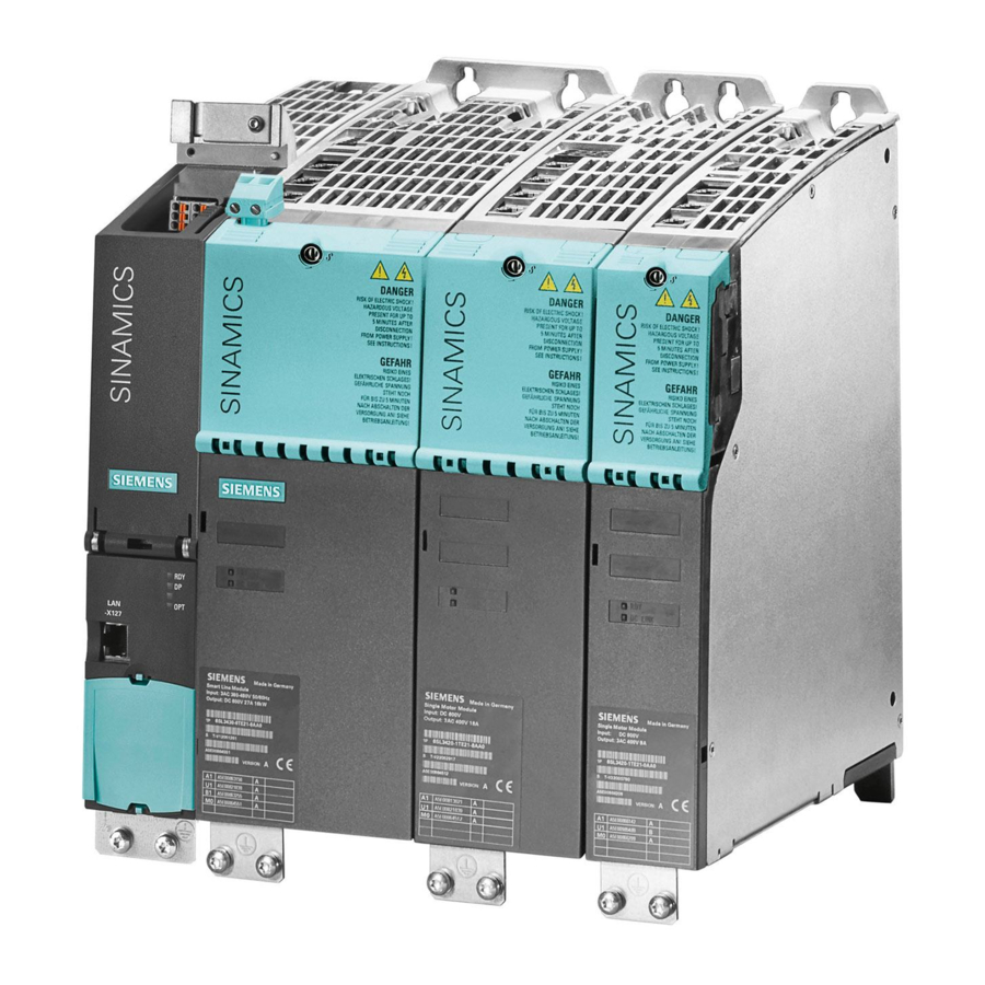
Connection methods SINAMICS drive I/O Figure 6-1 SINAMICS drive I/O 1PH4 Induction Motors Configuration Manual, (APH4S), 08/2008, 6SN1197-0AD64-0BP1... -
Page 118: Power Connection
Connection methods 6.2 Power connection Power connection Connecting motors Note The motors can be fed from a DC link voltage of up to 700 V DC. Table 6- 1 Overview, connection system for 1PH4 motors Number Max. cross-section that can be Terminal strip for PE connection size/ connected... - Page 119 If the brake feeder cables in the SIEMENS cable accessories are not used, then the brake conductor cores and shields must be connected to the cabinet ground (open-circuit cables result in capacitive charges!).
- Page 120 Connection methods 6.2 Power connection Current-carrying capacity for power and signal cables The current-carrying capacity of PVC/PUR-insulated copper cables is specified for routing types B1, B2 and C under continuous operating conditions in the table with reference to an ambient air temperature of 40 °C. For other ambient temperatures, the values must be corrected by the factors from the "Derating factors"...
-
Page 121: Signal Connection
Connection methods 6.3 Signal connection Signal connection DRIVE-CLiQ is the preferred method for connecting the encoder systems to SINAMICS. Motors with a DRIVE-CLiQ interface can be ordered for this purpose. Motors with a DRIVE- CLiQ interface can be directly connected to the associated motor module via the available MOTION-CONNECT DRIVE-CLiQ cables. - Page 122 Encoder connection on motors without DRIVE-CLiQ Motors without DRIVE-CLiQ require a Sensor Module Cabinet-Mounted or operation with SINAMICS S120. The Sensor Modules evaluate the signals from the connected motor encoders or external encoders and convert them to DRIVE-CLiQ. In conjunction with motor encoders, the motor temperature can also be evaluated using Sensor Modules.
- Page 123 Connection methods 6.3 Signal connection Cables on motors without DRIVE-CLiQ Only pre-assembled cables from Siemens (MOTION-CONNECT) may be used. Table 6- 5 Pre-assembled cable 6FX ☐ 002 - 2AC31 - ☐☐☐ ↓ ↓↓↓ ↓ Length 5 MOTION- max. cable length 100 m CONNECTⓇ500...
- Page 124 Connection methods 6.3 Signal connection 1PH4 Induction Motors Configuration Manual, (APH4S), 08/2008, 6SN1197-0AD64-0BP1...
-
Page 125: Information On The Application Of Motors
Information on the application of motors Transportation / storage before use During transportation and if the motors are out of operation for a long period of time, the cooling circuit must be completely emptied to protect against frost damage and corrosion. The motors should be stored indoors in dry, low-dust and low-vibration (v <... -
Page 126: Mounting Position/Types Of Construction
Information on the application of motors 7.4 Mounting position/types of construction Mounting position/types of construction Table 7- 1 Designation of types of construction (accdg. to IEC 60034-7) Type of Representation Description construction IM B35 Standard IM V15 Special construction types Observe the special conditions applicable to vertical axes! Note that a special seal is required for IM V36! IM V36... -
Page 127: Mounting
Information on the application of motors 7.5 Mounting Mounting Mounting instructions WARNING These motors are electrically operated. When electrical equipment is operated, certain parts of these motors are at hazardous voltage levels. If this motor is not correctly handled/operated, this can result in death or severe bodily injury as well as significant material damage. - Page 128 Information on the application of motors 7.5 Mounting Outgoing feeder on NDE Figure 7-2 Outgoing feeder Mounting information and instructions The following mounting instructions must be carefully observed: ● For high-speed machines, we recommend that the complete unit is dynamically balanced after couplings or belt pulleys have been mounted.
- Page 129 Information on the application of motors 7.5 Mounting Natural frequency when mounted The motor is a system which is capable of vibration at its natural frequency. For all 1PH motors, this resonant frequency lies above the specified maximum speed. When the motor is mounted onto a driven machine, a new system, which is capable of vibration, is created with modified natural frequencies.
- Page 130 Information on the application of motors 7.5 Mounting 1PH4 Induction Motors Configuration Manual, (APH4S), 08/2008, 6SN1197-0AD64-0BP1...
-
Page 131: Appendix
Appendix Description of terms Drive end Maximum continuous speed n The maximum permissible speed that is continuously permitted without speed duty cycles. Max. current I This is the maximum current (rms phase value) that can briefly flow for dynamic operations (e.g. - Page 132 Appendix A.1 Description of terms Modes The operating modes (duty types) are defined in IEC 60034, Part 1. The maximum duty cycle duration for duty types S1 and S6 is 10 minutes unless otherwise specified. Non-drive end No-load current I μ...
- Page 133 Appendix A.1 Description of terms S1 duty (continuous operation) Operation with a constant load, the duration of which is sufficient that the motor goes into a thermal steady-state condition. S6 duty (intermittent operation) S6 duty is operation which comprises a sequence of identical duty cycles; each of these duty cycles comprises a time with constant motor load and a no-load time.
-
Page 134: References
Appendix A.2 References References Overview of publications of planning manuals An updated overview of publications is available in a number of languages on the Internet at: www.siemens.com/motioncontrol Select "Support" → "Technical Documentation" → "Ordering Documentation" → "Printed Documentation". Catalogs Abbreviations... -
Page 135: Suggestions/Corrections
Appendix A.3 Suggestions/corrections Suggestions/corrections Should you come across any printing errors when reading this publication, please notify us on this sheet. We would also be grateful for any suggestions and recommendations for improvement. 1PH4 Induction Motors Configuration Manual, (APH4S), 08/2008, 6SN1197-0AD64-0BP1... - Page 136 Appendix A.3 Suggestions/corrections 1PH4 Induction Motors Configuration Manual, (APH4S), 08/2008, 6SN1197-0AD64-0BP1...
-
Page 137: Index
Index Absolute encoders, 97 Hotline, 6 Axial eccentricity tolerance, 58 Incremental encoder HTL, 93 Bearing change interval, 44 Incremental encoder sin/cos 1Vpp, 95 Bearing version, 43 Induced vibration, 129 Interfaces, 117 Concentricity tolerance, 58 Configuring, 29 Mounting, 127 Connecting-up information, 119 Mounting position, 126 Connection, 118 Construction types, 126... - Page 138 Siemens AG Industry Sector Motion Control Systems P.O. Box 3180 91050 ERLANGEN GERMANY www.siemens.com/motioncontrol...