Mackie M2600 Service Manual
Hide thumbs
Also See for M2600:
- Owner's manual (44 pages) ,
- Brochure (6 pages) ,
- Owner's manual (54 pages)

Related Manuals for Mackie M2600


Summary of Contents for Mackie M2600
-
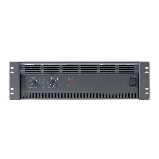
Page 1: Service Manual
Go To Bulletins M2600 FR Series Power Amplifier SERVICE MANUAL ©1998, ©1999 MACKIE DESIGNS, INC. 820-180-00 Page 3 is interactive... - Page 2 SERVICE ON THIS EQUIPMENT IS TO BE PERFORMED BY EXPERIENCED REPAIR TECHNICIANS ONLY...
-
Page 3: Table Of Contents
Mackie Designs, Service Technical Assistance, is available 8AM - 5PM PST, Monday through Friday for Authorized Mackie Service Centers, at 1-800-258-6883. Feel free to call with any questions and speak with a carefully-calibrated technician. If one is not available, leave a detailed message and a qualified Mackoid will return your call asap. -
Page 4: Block Diagram
Block diagram... -
Page 5: Specifications
Note: Power ratings are specified at 120VAC line voltages. Unconditionally stable, driving any reactive or capacitive load. The M2600 power amplifier draws large amounts of current from the AC line with continuous sine wave test- Turn On Delay: ing. Accurate measurement of power requires a steady 3-5 seconds and stable AC supply. -
Page 6: Troubleshooting Tips
Troubleshooting Tips-output failures After a catastrophic failure, it is likely that some of the supply fuses will be blown. Check and replace any fuses on the 129, 130, 133, and 171 boards. Short across the Left most lead of R1 to the right most lead of R2 on the 133 board to short out the two 15W inrush resistors (see the diagram on the next page). - Page 7 Various test points 170 board (Bias and check points) R146 R151 MUTE-VA -15V-AMP BIAS ADJUST BIAS POWER TRANSIENT TEST ADD A TEMPORARY SHORT (SEE TROUBLEHOOTING TIPS) 133 board (inrush bypassing) 186 board (fan speed adjustment) 129 channel board BR= BASE RESISTOR (2.2 OHM, 1/4W FUSIBLE) ER= EMITTER RESISTOR (0.33 OHM, 3W) +I SENSE -I SENSE...
-
Page 8: Reliability Verification
Reliability Verification Procedure After the unit has been repaired, the following should be done to assure long term reliable operation. If a distortion analyzer is present, distortion specifications should be verified. See the previous page for the 170 and 186 boards with some test points noted. 1. - Page 9 9. Place the amplifier in bridge mode and connect 4Ω loading to the bridge outputs (across both “+” output binding posts). The 4Ω dummy load should have a minimum power rating of 2000W. Slip some card stock between the heatsink-outlets and chassis sides to temporarily restrict the airflow.
-
Page 10: Circuit Theory
Circuit Theory Much of the circuitry in the M•2600 we hope is self explanatory from the schematics. This section will explain the unique circuits and architecture. Examples in this section will refer to Channel 1 for circuitry that is identical on both channels. INPUT CIRCUITRY The signal path begins with the INPUT BOARD (055-131-00). - Page 11 Most amplifiers use negative feedback to reduce this problem (creating a few more in the process). Mackie FR Series amplifiers take a different approach. By using two complementary “mirror image” front end circuits, any distortion caused by non-linear transistor curves is effectively canceled out in the bias string, without feedback! Another design feature unique to Mackie FR Series Amplifiers is the Baker Clamp.
- Page 12 SOA protection There are two SOA detectors in the M-2600: One that monitors steady state output stage dissipation and one that monitors transient high current events. Both detectors need to monitor the output stage current. A voltage, representing output stage current, is derived by first sampling the voltage drop across the output transistor emitter resistors.
- Page 13 via R33 and R8 and compared against the 5V reference at U3A. If the AC line voltage falls to around 60% of nominal (around 70VAC), the output of U3A goes low, resetting the mute and short monostables via D5 and D12. If the +15V supply fails, D3 and D4 bias the U3A inputs such that the amplifier is also muted.
- Page 14 Final Assembly...
-
Page 20: Parts List
Master Parts List 090-078-00 M2600 Assembly, 120v Item# Part # Description 040-257-00 CBL ASSY 24GA 3P .098 6IN NOTE:The Item numbers in 040-272-00 DIS 14G 1010 BRN 7.5 QDX2 040-273-00 DIS 14G 1010 BLU 6.5 QDX2 the first column of this page... - Page 21 055-129-00-01 PCB ASSY CHANNEL 1 - 2600 Amplfier/Heatsink Assemby 055-130-00-01 PCB ASSY CHANNEL 2 - 2600 055-170-00-02 PCB ASSY V-AMP PROT M2600 A3 Drawings on pages 17-19 055-186-00-01 PCB ASSY PREDRV/FAN M2600 A2 080-116-00 FAN ASSY M2600 410-013-00...
- Page 22 400-129-00 FUSE CLIP 0.25 DIA PC MNT Z1-4 400-231-00 HEADER, 2X5, MATE-N-LOCK 400-242-00 CONNECTOR,STR,3P,.098 X 1,SHRD 400-243-00 CONNECTOR,STR,2P,.098 X 1,SHRD 450-129-00 PCB, M2600 CH-1 AMP 490-021-00 MAGNET, .2THK .5DIA 501-003-00 RELAY, SPDT T9AS5D12-24 510-041-00 FUSE 25A FB 3AG F1-2 601-006-00...
- Page 23 FUSE CLIP 0.25 DIA PC MNT Z1-3 Z5 400-173-00 CONN QUICK DISC .250 W/STABLE-LOK TABS 400-231-00 HEADER, 2X5, MATE-N-LOCK 450-130-00 PCB M2600 CH-2 AMP 490-021-00 MAGNET .200 THK X .50 DIA 501-003-00 RELAY, SPDT T9AS5D12-24 510-041-00 FUSE 25A FB 3AG...
- Page 24 055-131-00-01 Rev A Input board Part # Description Value Reference Designator DO NOT STUFF C22 C24 040-258-00 RIB 28GA TRAN 20C .1 5IN 040-259-00 RIB 28GA TRAN 20C .1 6IN 040-260-00 RIB 28GA TRAN 20C .1 20IN 100-027-00 RESISTOR CF R23 R28-29 R50-51 R65 130-062-02 RES POT 12MM HORIZ DUAL...
- Page 25 X-SISTOR PNP SMD IMBT4403 Q1-2 320-012-00 OPAMP NJM4560M NJM4560M U1 U6 323-002-00 I.C. QUAD COMPARATOR SMD LM339 U2-5 U7 400-077-00 HEADER STR LCK SHRD 20P .100 X 2 450-132-00 PCB, M2600 DISPLAY 706-033-08 STANDOFF, SWAGE, 4-40 X .665L H1-3 H5-7...
- Page 26 -00 AND -02 ASSY ONLY 400-173-00 CONN QUICK DISC .250 -01 ASSY ONLY 400-242-00 CONNECTOR,STR,3P,.098 X 1,SHRD 450-133-00 PCB, M2600 PWR DISTRO & AC-INRUSH 501-003-00 RELAY, SPDT T9AS5D12-24 510-017-00 FUSE 20A SLO-BLO -02 ASSY ONLY (100 VOLT MODELS ONLY) 510-018-00...
- Page 27 055-170-00 Rev A, Voltage amplifier and protection Part # Description Value Reference Designator TEST POINT, PART OF PCB J1-9 J11-16 J24-26 100-025-00 RESISTOR CF R11 R30 R37-38 105-369-00 RES MF .125W 1% 6K19 OHM 6K19 R141-144 130-021-00 RESISTOR POT TRIM HORIZ 10KB R162 130-053-00...
- Page 28 CONN, HDR, 3-PIN, UN-SHROUDED 0 .100 J21-22 400-171-00 CONN, HDR, 2-PIN, UN-SHROUDED, 0 .100 J17-20 J23 400-186-00 CONN HDR 40P .100 X 2 STR SHRD 450-170-00 PCB, M2600 V-AMP & PROTECTION 550-369-00 BRACKET, L H1-2 601-008-00 INDUCTOR 10uH L1-2 712-021-01...
- Page 29 400-133-00 HEADER, 2X3, MATE-N-LOCK 400-173-00 CONN QUICK DISC .250 J3-5 W/STABLE-LOK TABS 400-231-00 HEADER, 2X5, MATE-N-LOCK J1-2 450-171-00 PCB, M2600, POWER SUPPLY 510-026-00 FUSE 5X20 T-3.15A F1-2 055-172-00-01 Rev A Speaker output board Part # Description Value Reference Designator 400-138-01...
- Page 30 I.C. LINEAR POS 3 TERM VOLTAGE LM 7815 REGULATOR 400-078-00 CONNECTOR STR LCK SHRD 10P .100 X 2 400-171-00 CONN, HDR, 2-PIN, UN-SHROUDED, 0 .100 450-186-00 PCB, M2600, +/-15V SUPPLY & FAN DRIVE 550-369-00 BRACKET, L H1-2 601-013-00 CHOKE, POWER AXIAL 470uH...
- Page 31 M•2600 amplifier modification instructions Models affected: All M•2600 amplifiers with serial numbers “AU” or those less than DX10017. Add this mod as part of your normal repair procedures. Symptom: No signal, dead channel or distorted output. Possible Cause: Transistor Q5 on the V-amp protection boards may be shorted to an adjacent trace. Transistors Q3 and Q4 on the V-amp protection boards may oscillate under certain conditions, causing V-amp board failure, and/or failure of R57 on Ch.1 amp board and R56 on CH.2 amp board (33Ω...
- Page 32 THE MACKIE FIXER • MACKIE DESIGNS SERVICE NEWS Amplifier Subassembly 055-170-00 V-AMP board Solder here Cut trace here Change R20 and R21 Change R14 Cut trace here Solder an insulated wire here and R15 M•2600 modification SSE July 2000 M2600mod.pdf, page 2 of 2...