
Related Manuals for Agilent Technologies 34921A

Summary of Contents for Agilent Technologies 34921A
- Page 1 Agilent 34921A-34925A Low Frequency Multiplexer Modules User’s Guide Agilent Technologies, Inc. Printed in Malaysia Edition 1 June 2008 E0608 *34980-90021* 34980-90021 Agilent Technologies...
- Page 2 (Technical Data) and 12.212 (Computer Software) and, for the Department of Defense, DFARS 252.227-7015 (Technical Data - Commercial Items) and DFARS 227.7202-3 (Rights in Commercial Com- puter Software or Computer Software Documentation). Agilent 34921A-34925A Low Frequency Multiplexer Modules User’s Guide...
- Page 3 Do Not Remove the Instrument Cover Only qualified, service-trained personal who are aware of the hazards involved should remove instrument covers. Always disconnect the power cable and any exter- nal circuits before removing the instrument cover. Agilent 34921A-34925A Low Frequency Multiplexer Modules User’s Guide...
- Page 4 The Declaration of Conformity (DoC) for the 34980A mainframe instrument can be found on page iii in the 34980A Mainframe User’s Guide. That DoC applies to the 34980A mainframe and all available plug- in modules. Agilent 34921A-34925A Low Frequency Multiplexer Modules User’s Guide...
-
Page 5: Table Of Contents
34921A Simplified Schematic........ - Page 6 Agilent 34921A-34925A Low Frequency Multiplexer Modules User’s Guide...
-
Page 7: Low Frequency Multiplexer Modules
• You can connect a MUX to an external instrument, and/or switch multiple analog signals to the internal DMM. • With the 34921A, 34922A, 34923A, and the 34924A modules, you can close more than one channel in each bank simultaneously (N:1 configuration). -
Page 8: Measurement Functions For The Multiplexer Modules
100 series resistors are bypassed on module. Ω Ω 10 k or higher range used for loads over approximately 300 due to series resistance of FET channels. Agilent 34921A-34925A Low Frequency Multiplexer Modules User’s Guide... -
Page 9: Operating Considerations
• The simulation setting is stored in volatile memory and will be lost when power is turned off. To re- enable the simulation mode after power has been off, you must send the command again. Agilent 34921A-34925A Low Frequency Multiplexer Modules User’s Guide... -
Page 10: Scpi Programming Examples For The Multiplexer Modules
“break- before- make” series. ROUTe:CLOSe (@3001:3040) The following command opens the closed channel on Bank 1 of a FET MUX module in slot 3, and closes channel 15 on that bank. ROUTe:CLOSe (@3015) Agilent 34921A-34925A Low Frequency Multiplexer Modules User’s Guide... - Page 11 FETCh? Example: Making current measurements The following command configures channel 43 for a 34921A modules in slot 7 for dc current measurements, triggers the internal DMM to scan the channel, and then sends the reading to the output buffer of the 34980A. The default settings for range (autorange) and resolution (1 PLC) are used for the measurement.
- Page 12 7 and 16 for a MUX module in slot 1. DIAGnostic:RELay:CYCLes:CLEar (@1007,1016) Example: Resetting module(s) to power-on state The following command resets a module in slot 4 to its power- on state. SYSTem:CPON 4 Agilent 34921A-34925A Low Frequency Multiplexer Modules User’s Guide...
-
Page 13: 34921A 40-Channel Armature Multiplexer With Low Thermal Offset
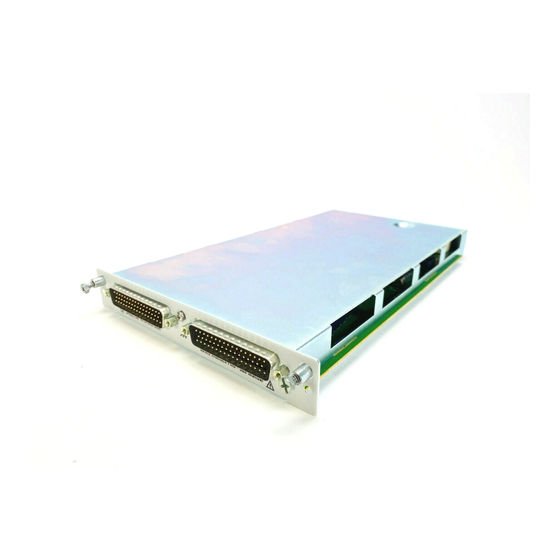
34921A 40-Channel Armature Multiplexer with Low Thermal Offset 34921A 40-Channel Armature Multiplexer with Low Thermal Offset The 34921A 40- Channel Armature Multiplexer (40- Ch Arm MUX) is divided into two banks with 20 latching armature switches (channels 1- 20 and 21- 40) in each. This module also offers four additional fused relays (channels 41- 44) for making AC and DC current measurements with the internal DMM with no external shunts needed. - Page 14 34921A 40-Channel Armature Multiplexer with Low Thermal Offset Low thermal offset voltage makes the 34921A ideal for low- level signal switching. The 34921T optional terminal block provides a built- in thermocouple reference junction that helps minimize errors due to thermal offset when you measure thermocouples.
-
Page 15: 34921A Simplified Schematic
34921A 40-Channel Armature Multiplexer with Low Thermal Offset 34921A Simplified Schematic This drawing shows two independent 20- channel 2- wire MUXes. NOTE: The three-digit number assigned to each switch represents the channel number. NOTE: Bank Relays: Armature latching Bank 1... -
Page 16: 34921A D-Sub Connectors
34921A 40-Channel Armature Multiplexer with Low Thermal Offset 34921A D-Sub Connectors Bank 1 Bank 2 Bank 1 For orientation, the D-sub connector end of the module is facing you. 14L 5H 20H 20L Interlock1 50-Pin D-Sub *TSIL = Temperature Sensor Male Connector Interface Line. -
Page 17: 34921T Terminal Block
The cables provide communication and power to the temperature sensor on the 34921T terminal block. If cabling is not correct, an error may occur indicating that the 34921A module is not fully operational. Agilent 34921A-34925A Low Frequency Multiplexer Modules User’s Guide... - Page 18 34921A 40-Channel Armature Multiplexer with Low Thermal Offset The 34980A Product Reference CD (shipped with the instrument) contains a 34921T Wiring Log for you to document your wiring configuration for this module. You can open the wiring log file in Microsoft® Excel® or Adobe®...
-
Page 19: 34922A 70-Channel Armature Multiplexer
Analog Bus. For more information, see “Safety Interlock” on page 3 and “34922A D- Sub Connectors” on page 15. When the power is off, all channel relays maintain state, and the Analog Bus relays open. Agilent 34921A-34925A Low Frequency Multiplexer Modules User’s Guide... -
Page 20: 34922A Simplified Schematic
NOTE: Bank Relays: Armature latching Analog Bus Relays: Armature non-latching Bank 1 COM 1 Analog Buses ABus1 ABus2 ABus3 ABus4 (MEAS) (SENS) COM 2 Bank 2 Agilent 34921A-34925A Low Frequency Multiplexer Modules User’s Guide... -
Page 21: 34922A D-Sub Connectors
Bank 1 Analog Bus relays to close. The optional 34922T terminal blocks short these pins for you. This feature protects inadvertent routing of high voltages from the Analog Buses to the D-sub connector of the module. Agilent 34921A-34925A Low Frequency Multiplexer Modules User’s Guide... - Page 22 Bank 2 Analog Bus relays to close. the optional 34922T terminal blocks short these pins for you. This feature protects inadvertent routing of high voltages from the Analog Buses to the D-sub connector of the module. Agilent 34921A-34925A Low Frequency Multiplexer Modules User’s Guide...
-
Page 23: 34922T Terminal Blocks
This terminal block with solder- type connections is labeled with the model number and the abbreviated module name. In addition, space is available on the label for you to write the slot number. Agilent 34921A-34925A Low Frequency Multiplexer Modules User’s Guide... - Page 24 This terminal block with screw- type connections is labeled with the model number and the abbreviated module name. In addition, space is available on the label for you to write the slot number. COM2 36 COM1 Agilent 34921A-34925A Low Frequency Multiplexer Modules User’s Guide...
-
Page 25: 34923A 40/80-Channel Reed Multiplexer
Lifetime of relays is severely degraded as current or voltage goes up. If higher voltage is being switched, limits on source current are recommended. When the power is off, all channel and Analog Bus relays open. Agilent 34921A-34925A Low Frequency Multiplexer Modules User’s Guide... -
Page 26: Two-Wire Mode
Analog Bus relay closed you can close up to a maximum of 39 channel relays. If you try to close more than the allowed number of channels, you will receive an error message. Agilent 34921A-34925A Low Frequency Multiplexer Modules User’s Guide... -
Page 27: 34923A Simplified Schematic For Two- Or Four-Wire Mode
Bank Relays: Reed non-latching Analog Bus Relays: Armature non-latching COM 1 100Ω 100Ω 100Ω 100Ω 100Ω 100Ω Analog Buses ABus1 ABus2 ABus3 ABus4 (MEAS) (SENS) 100Ω 100Ω 100Ω 100Ω 100Ω 100Ω COM 2 Bank 2 Agilent 34921A-34925A Low Frequency Multiplexer Modules User’s Guide... -
Page 28: 34923A D-Sub Connectors For Two- Or Four-Wire Mode
34923T-001 (for 2-wire) shorts these pins for you. This feature Reserved protects inadvertent Reserved routing of high voltages Reserved from the Analog Buses to Reserved the D-sub connector of the module. Reserved Agilent 34921A-34925A Low Frequency Multiplexer Modules User’s Guide... -
Page 29: 34923T-001 Terminal Block For Two-Wire Or Four-Wire Mode
The 34980A Product Reference CD (shipped with the instrument) contains a 34923T (2- wire mode) Wiring Log for you to document your wiring configuration for this module. You can open the wiring log file in Microsoft® Excel® or Adobe® Acrobat® format. Agilent 34921A-34925A Low Frequency Multiplexer Modules User’s Guide... -
Page 30: 34923A Simplified Schematic For One-Wire Mode
Bank relays: Reed non-latching Analog Bus relays: Armature non-latching COM 1 100Ω 100Ω 100Ω 100Ω 100Ω 100Ω Analog Buses ABus1 ABus2 ABus3 ABus4 (MEAS) (SENS) 100Ω 100Ω 100Ω 100Ω 100Ω 100Ω COM 2 Bank 2 Agilent 34921A-34925A Low Frequency Multiplexer Modules User’s Guide... -
Page 31: 34923A D-Sub Connectors For One-Wire Mode
34923T-002 (for 1-wire) shorts these pins for you. This feature Reserved protects inadvertent Reserved routing of high voltages Reserved from the Analog Buses to Reserved the D-sub connector of Reserved the module. Agilent 34921A-34925A Low Frequency Multiplexer Modules User’s Guide... -
Page 32: 34923T-002 Terminal Block For One-Wire Mode
The 34980A Product Reference CD (shipped with the instrument) contains a 34923T (1- wire mode) Wiring Log for you to document your wiring configuration for this module. You can open the wiring log file in Microsoft® Excel® or Adobe® Acrobat® format. Agilent 34921A-34925A Low Frequency Multiplexer Modules User’s Guide... -
Page 33: 34924A 70-Channel Reed Multiplexer
100 in-rush resistors protect the reed relays from damage and performance degradation. Therefore, you must consider these resistors when you are designing a measurement. Refer to the simplified schematic page Agilent 34921A-34925A Low Frequency Multiplexer Modules User’s Guide... - Page 34 Lifetime of relays is severely degraded as current or voltage goes up. If higher voltage is being switched, limits on source current are recommended. When the power is off, all channel and Analog Bus relays open. Agilent 34921A-34925A Low Frequency Multiplexer Modules User’s Guide...
-
Page 35: 34924A Simplified Schematic
Analog Bus relays: Armature non-latching Bank 1 COM 1 100Ω 100Ω 100Ω 100Ω 100Ω 100Ω Analog Buses ABus1 ABus2 ABus3 ABus4 (MEAS) (SENS) 100Ω 100Ω 100Ω 100Ω 100Ω 100Ω COM 2 Bank 2 Agilent 34921A-34925A Low Frequency Multiplexer Modules User’s Guide... -
Page 36: 34924A D-Sub Connectors
Bank 1 Analog Bus relays to close. The optional 34924T terminal blocks short these pins for you. This feature protects inadvertent routing of high voltages from the Analog Buses to the D-sub connector of the module. Agilent 34921A-34925A Low Frequency Multiplexer Modules User’s Guide... - Page 37 Bank 2 Analog Bus relays to close. The optional 34924T terminal blocks short these pins for you. This feature protects inadvertent routing of high voltages from the Analog Buses to the D-sub connector of the module. Agilent 34921A-34925A Low Frequency Multiplexer Modules User’s Guide...
-
Page 38: 34924T Terminal Blocks
This terminal block with solder- type connections is labeled with the model number and the abbreviated module name. In addition, space is available on the label for you to write the slot number. Agilent 34921A-34925A Low Frequency Multiplexer Modules User’s Guide... - Page 39 This terminal block with screw- type connections is labeled with the model number and the abbreviated module name. In addition, space is available on the label for you to write the slot number. COM2 36 COM1 Agilent 34921A-34925A Low Frequency Multiplexer Modules User’s Guide...
-
Page 40: 34925A 40/80-Channel Optically-Isolated Fet Multiplexer
Bank 2 (sense) to provide these connections. Four- wire controls occur only when doing 4- wire measurement operations through the internal DMM, such as MEASure:FRESistance? or scanning a channel previously configured as 4- wire. Agilent 34921A-34925A Low Frequency Multiplexer Modules User’s Guide... -
Page 41: One-Wire Mode
Further FET protection is assured only as one channel in each bank is closed at any time. Thus this module will operate as only a 1:N MUX module. For more information about FET channel closures, refer to page Agilent 34921A-34925A Low Frequency Multiplexer Modules User’s Guide... -
Page 42: 34925A Simplified Schematic For Two- Or Four-Wire Mode
Analog Bus relays: Armature non-latching 100Ω Bank 1 Overvoltage Protection (each channel) COM 1 Analog Buses ABus1 ABus2 ABus3 ABus4 (MEAS) (SENS) COM 2 100Ω 51.1Ω Bank 2 11Ω 11Ω Current-Limiting Circuitry Agilent 34921A-34925A Low Frequency Multiplexer Modules User’s Guide... -
Page 43: 34925A D-Sub Connectors For Two- Or Four-Wire Mode
This feature protects No Connect 47 inadvertent routing of No Connect 48 high voltages from the No Connect 49 Analog Buses to the No Connect 50 D-sub connector of the Agilent 34921A-34925A Low Frequency Multiplexer Modules User’s Guide... -
Page 44: 34925T-001 Terminal Block For Two-Wire Or Four-Wire Mode
The 34980A Product Reference CD (shipped with the instrument) contains a 34925T (2- wire mode) Wiring Log for you to document your wiring configuration for this module. You can open the wiring log file in Microsoft® Excel® or Adobe® Acrobat® format. Agilent 34921A-34925A Low Frequency Multiplexer Modules User’s Guide... -
Page 45: 34925A Simplified Schematic For One-Wire Mode
Bank relays: FET non-latching Analog Bus relays: Armature non-latching Overvoltage Protection Bank 1 (each channel) COM 1 Analog Buses ABus1 ABus2 ABus3 ABus4 (MEAS) (SENS) COM 2 100Ω 51.1Ω 11Ω 11Ω Current-Limiting Circuitry Bank 2 Agilent 34921A-34925A Low Frequency Multiplexer Modules User’s Guide... -
Page 46: 34925A D-Sub Connectors For One-Wired Mode
This feature protects No Connect 47 inadvertent routing of No Connect 48 high voltages from the No Connect 49 Analog Buses to the No Connect 50 D-sub connector of the Agilent 34921A-34925A Low Frequency Multiplexer Modules User’s Guide... -
Page 47: 34925T-002 Terminal Block For One-Wire Mode
The 34980A Product Reference CD (shipped with the instrument) contains a 34925T (1- wire mode) Wiring Log for you to document your wiring configuration for this module. You can open the wiring log file in Microsoft® Excel® or Adobe® Acrobat® format. Agilent 34921A-34925A Low Frequency Multiplexer Modules User’s Guide... - Page 48 34925A 40/80-Channel Optically-Isolated FET Multiplexer Agilent 34921A-34925A Low Frequency Multiplexer Modules User’s Guide...
- Page 49 34923T Option 002, wiring log, 38, 34924T Option 001, 34924T Option 002, 34925T Option 001, 34925T Option 002, connector pinouts 34921A, 34922A, 34923A, 22, warranty, 34924A, 34925A, 37, D-sub pinouts Agilent 34921A-34925A Low Frequency Multiplexer Modules User’s Guide...
- Page 50 Index Agilent 34921A-34925A Low Frequency Multiplexer Modules User’s Guide...