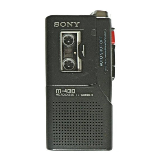
Sony m-430 Service Manual
Hide thumbs
Also See for m-430:
- Specifications (2 pages) ,
- Operating instructions (2 pages) ,
- Operating instructions (2 pages)
Table of Contents
Advertisement
SERVICE MANUAL
Ver 1.0 1999. 02
Tape
y (normal position type)
Recording system
2-track 1-channel monaural
Speaker
Approx. 3.6 cm (1
in.) dia.
7/16
Tape speed
2.4 cm/s (
ips), 1.2 cm/s (
15/16
15/32
Frequency range
250 - 4,000 Hz (with TAPE SPEED switch at 2.4 cm/s)
Output
Earphone jack (minijack) for 8 - 300 ohms earphone
Power output (at 10% harmonic distortion)
160 mW
Power requirements
3 V DC batteries size AA (R6) × 2/External DC 3 V power sources
Dimensions (w/h/d)
Approx. 62.2 × 121.5 × 24.3 mm (2
parts and controls
Mass
Approx. 125 g (4.5
)
oz.
MICROFILM
SPECIFICATIONS
ips)
× 4
×
in.) incl. projecting
1/2
7/8
31/32
Model Name Using Similar Mechanism
Tape Transport Mechanism Type
Supplied accessory
Microcassette tape MC-30 (1)
Design and specifications are subject to change without notice.
MICROCASSETTE
– 1 –
M-430
US Model
AEP Model
E Model
NEW
MZ-430-99
TM
-CORDER
Advertisement
Table of Contents

Related Manuals for Sony m-430


Summary of Contents for Sony m-430
- Page 1 M-430 SERVICE MANUAL US Model AEP Model Ver 1.0 1999. 02 E Model Model Name Using Similar Mechanism Tape Transport Mechanism Type MZ-430-99 SPECIFICATIONS Tape Supplied accessory y (normal position type) Microcassette tape MC-30 (1) Recording system 2-track 1-channel monaural Design and specifications are subject to change without notice.
-
Page 2: Table Of Contents
TABLE OF CONTENTS 1. GENERAL ..............2. DISASSEMBLY 2-1. Lid Assy, Cassette ............... 4 2-2. Lid, Battery Case ..............5 2-3. Cabinet (Rear) Assy ............5 2-4. Main Board ................. 6 2-5. Mechanism Deck ..............6 2-6. Head, Ceramic ..............7 3. -
Page 3: General
SECTION 1 GENERAL This section is extracted from instruction manual. – 3 –... -
Page 4: Disassembly
SECTION 2 DISASSEMBLY • The equipment can be removed using the following procedure. Lid assy, Cabinet (rear) Main Mechanism Head, cassette assy board deck ceramic Lid, battery case Note : Follow the disassembly procedure in the numerical order given. 2-1. LID ASSY, CASSETTE top view cabinet (front) precision screwdriver... -
Page 5: Lid, Battery Case
2-2. LID, BATTERY CASE 3 claws 5 lid, battery case 2-3. CABINET (REAR) ASSY Note : When installing, fit the knobs and switches. 1 screw (1.7x16) 3 screw (B1.7x5), tapping 2 screw (1.7x16) 5 claw 6 cabinet (rear) assy knob 4 claws switch –... -
Page 6: Main Board
2-4. MAIN BOARD 7 (M1.4x3.0), locking 1 Unsolder the 2 places. 2 Unsolder the 2 places. 8 (M1.4x3.0), locking 3 Unsolder the 4 places. 6 mic assy 4 Unsolder the 2 places. 9 MAIN board 5 Unsolder the 2 places. 2-5. -
Page 7: Head, Ceramic
2-6. HEAD, CERAMIC 2 arm (pinch roller) assy 3 M1.4, special head 4 M1.4, special head 5 head, ceramic 1 claw – 7 –... -
Page 8: Mechanical Adjustments
SECTION 3 SECTION 4 MECHANICAL ADJUSTMENTS ELECTRICAL ADJUSTMENTS PRECAUTION Test Tape 1. Clean the following parts with a denatured-alcohol-moistened Tape Speed swab : Type Signal Used for (cm/s) record/playback/erase head pinch roller S-2-A030 3 kHz, – 20 dB Head Azimuth Adjustment rubber belts capstan 2. -
Page 9: Diagrams
M-430 SECTION 5 DIAGRAMS Tape Speed Adjustment Adjustment Location : 5-1. BLOCK DIAGRAM First remove the plate, blind. Setting: VOL control : mechanical mid Remove the plate, blind. Procedure: • Reform 2.4 cm/s speed adjustment before 1.2 cm/s speed adjustment mode : playback... -
Page 10: Printed Wiring Board
M-430 5-2. PRINTED WIRING BOARD HRPE901 REC/PB/ERASE HEAD HD– (REC/PB) • Semiconductor (ERASE) HE– Location Ref. No. Location D102 Note: IC101 • X : parts extracted from the component side. IC601 • b : Pattern from the side which enables seeing. -
Page 11: Schematic Diagram
M-430 5-3. SCHEMATIC DIAGRAM Note: • IC Block Diagram • All capacitors are in µF unless otherwise noted. pF: µµF 50 WV or less are not indicated except for electrolytics and tantalums. IC601 LA5521MTP-2 • All resistors are in Ω and W or less unless otherwise specified. -
Page 12: Exploded Views
SECTION 6 EXPLODED VIEWS NOTE: 6-2. MACHANISM DECK SECTION • The mechanical parts with no reference • -XX and -X mean standardized parts, so • Accessories and packing materials are (MZ-430-99) number in the exploded views are not supplied. they may have some difference from the given in the last of this parts list. -
Page 13: Electrical Parts List
SECTION 7 MAIN ELECTRICAL PARTS LIST NOTE: • Due to standardization, replacements in • Items marked “*” are not stocked since When indicating parts by reference the parts list may be different from the they are seldom required for routine service. number, please include the board. - Page 14 M-430 MAIN Ref. No. Part No. Description Remark R125 1-216-041-11 METAL CHIP 1/10W R126 1-216-057-00 METAL CHIP 2.2K 1/10W R129 1-216-021-00 METAL CHIP 1/10W R601 1-216-041-11 METAL CHIP 1/10W R602 1-216-069-11 METAL CHIP 6.8K 1/10W R603 1-216-033-00 METAL CHIP 1/10W...