Table of Contents
Advertisement
Quick Links
Advertisement
Table of Contents

Related Manuals for IBM RackSwitch G8264CS


Summary of Contents for IBM RackSwitch G8264CS
- Page 1 IBM System Networking RackSwitch G8264CS Installation Guide...
- Page 3 IBM System Networking RackSwitch G8264CS Installation Guide...
- Page 4 Note: Before using this information and the product it supports, read the Warranty Information document, the general information in Appendix B, “Notices,” on page 67, and the Important Notices document that comes with the product. Read the IBM Safety Notices and the License Agreement for Machine Code (LAMC) document on the IBM Documentation CD.
- Page 5 Prima di installare questo prodotto, leggere le Informazioni sulla Sicurezza. Les sikkerhetsinformasjonen (Safety Information) før du installerer dette produktet. Antes de instalar este produto, leia as Informações sobre Segurança. Antes de instalar este producto, lea la información de seguridad. © Copyright IBM Corp. 2014...
- Page 6 Hazardous voltage, current, or energy levels are present inside any component that has this label attached. Do not open any cover or barrier that contains this label. (L001) DANGER Rack-mounted devices are not to be used as shelves or work spaces. (L002) IBM System Networking RackSwitch G8264CS: Installation Guide...
- Page 7 DANGER Multiple power cords. The product might be equipped with multiple power cords. To remove all hazardous voltages, disconnect all power cords. (L003) Safety...
- Page 8 It is the responsibility of the customer to ensure that the outlet is correctly wired and grounded to prevent an electrical shock. (D004) IBM System Networking RackSwitch G8264CS: Installation Guide...
- Page 9 Electrical voltage and current from power, telephone, and communication cables are hazardous. To avoid a shock hazard: v Connect power to this unit only with the IBM provided power cord. Do not use the IBM provided power cord for any other product.
- Page 10 (C027) CAUTION: This product contains a Class 1M laser. Do not view directly with optical instruments. (C028) viii IBM System Networking RackSwitch G8264CS: Installation Guide...
- Page 11 DANGER Observe the following precautions when working on or around your IT rack system: v Heavy equipment—personal injury or equipment damage might result if mishandled. v Always lower the leveling pads on the rack cabinet. v Always install stabilizer brackets on the rack cabinet. v To avoid hazardous conditions due to uneven mechanical loading, always install the heaviest devices in the bottom of the rack cabinet.
- Page 12 (R001 part 2 of 2) Important: This product is also designed for IT power distribution systems with phase-to-phase voltage of 230V. Important: Machinenlärminformations-Verordnung - 3. GPSGV, der höchste Shalldruckpegel beträgt 70 dB (A) oder weniger. IBM System Networking RackSwitch G8264CS: Installation Guide...
-
Page 13: Table Of Contents
Chapter 1. Introduction ..... . 1 The IBM Documentation CD ....1 Hardware and software requirements . - Page 14 ....65 How to send Dynamic System Analysis data to IBM ... 66 Using the documentation .
-
Page 15: Chapter 1. Introduction
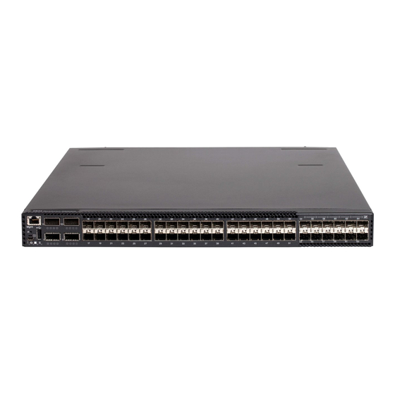
Ethernet packets at low latency on all ports. The IBM System Networking RackSwitch G8264CS contains thirty-six 10 GbE small form-factor pluggable plus (SFP+) ports and four 40 GbE quad small form-factor pluggable plus (QSFP+) ports, and twelve Omni Ports. -
Page 16: Hardware And Software Requirements
Notices and statements in this document The caution and danger statements in this document are also in the multilingual Safety Information document, which is on the IBM Documentation CD. Each statement is numbered for reference to the corresponding statement in the Safety Information document. -
Page 17: Rackswitch G8264Cs Features
A danger statement is placed just before the description of a potentially lethal or extremely hazardous procedure step or situation. RackSwitch G8264CS features This section provides an overview of IBM System Networking RackSwitch G8264CS features. Performance v 1.2 Tbps Ethernet throughput (full duplex), non-blocking switching architecture... -
Page 18: Major Components
– 802.1p priority queues – Differentiated Services Code Point (DSCP) support v Convergence – Support for IBM vNIC (virtual Network Interface Card) Virtual Fabric Adapter – Support for Converged Enhanced Ethernet (CEE) (PFC, ETS, DCBX) v Availability – Layer 2 failover –... -
Page 19: Reset Button
The following illustrations show the ports and controls on the front and rear of the switch. Figure 1. IBM System Networking RackSwitch G8264CS front panel Figure 2. IBM System Networking RackSwitch G8264CS front panel detail Figure 3. IBM System Networking RackSwitch G80264CS rear panel Reset button The Reset button is recessed within a hole on the front panel. -
Page 20: Ac Power Supply
You can replace a hot-swap power supply module without powering off the switch or disrupting switch functions. DANGER Multiple power cords. This product might be equipped with multiple power cords. To remove all hazardous voltages, disconnect all power cords. (L003) IBM System Networking RackSwitch G8264CS: Installation Guide... -
Page 21: Switch Ports
There is no power switch on the IBM System Networking RackSwitch G8264CS; the switch unit powers up when power is supplied through the power cords. The Power Supply LED indicates the status of the power supplies. The LED flashes when only one power cord is connected, and is steady when both power cords are connected. - Page 22 IBM 10 GBASE-SR SFP+ transceivers. The 40 GBASE-SR4 specification (802.3ba-2010) indicates a higher optical power level than standard 10 GBASE-SR. IBM SFP+ SR transceivers can handle the higher optical power levels. This cable must be purchased separately from your fiber cable supplier.
-
Page 23: Console Port
Fibre Channel/Ethernet Omni Ports Features of Fibre Channel/Ethernet Omni Ports include: v Each Omni Port is capable of running in 10 Gb Ethernet mode or four to eight Gb Fibre Channel (FC) mode with auto-negotiation capability. v Support for NPV (N_Port Virtualization) Gateway provides connectivity to the Fibre Channel SAN. -
Page 24: Switch Leds
USB drive to the switch. You can also start the switch using files on the USB drive. For more information about using the USB drive, see the IBM System Networking RackSwitch G8264CS Release Notes. Switch LEDs The following illustration shows the switch LEDs. - Page 25 The switch LEDs are located on the front panel and are described in the following table. Table 4. Switch LED descriptions Function Master Member Power supply Service Total Power Failure Service Required Flashing blue See below See below See below Power Supplies OK Solid green Not applicable...
-
Page 26: Technical Specifications
Technical specifications The IBM System Networking RackSwitch G8624CS technical specifications are described in the following sections. Physical characteristics The physical characteristics of the System Networking RackSwitch G8264CS are listed in the following table. Table 9. Physical characteristics Specification Physical characteristics Dimensions (H x W x D) 4.45 x 43.9 x 48.26 cm. -
Page 27: Environmental Specifications
Environmental specifications The environmental specifications for the switch are listed in the following table. Table 10. Environmental specifications Specification Measurement Temperature, ambient operating 0° C to +40° C (32° F to 104° F) with four fans Temperature (fan failure), operating 0°... - Page 28 IBM System Networking RackSwitch G8264CS: Installation Guide...
-
Page 29: Chapter 2. Installing The Rackswitch And Options
“Installing the RackSwitch in a standard equipment rack” on page 19 v “Installing the RackSwitch in an IBM iDataPlex rack” on page 22 v “Installing the RackSwitch in an IBM System x or Power rack” on page 25 v “Installing the 1U air duct option” on page 28 v “Installing an SFP, SFP+, QSFP+, and Omni Port transceiver”... -
Page 30: Required Tools
MAC addresses for other _____________________________________________ components _____________________________________________ _____________________________________________ Required tools You need the following tools or equipment to install the IBM System Networking RackSwitch G8264CS: v Standard flat-blade screwdriver v #2 Phillips screwdriver v Electrostatic discharge wrist strap Package contents... -
Page 31: Environmental Requirements
Mini-USB to RJ-45 serial cable, category 5 patch cable, RJ-45 to DB9 adapter v One AC power cords v One IBM Documentation CD which includes the Installation Guide (this document) and the IBM Systems Safety Notices document. v One Environmental Notices CD... - Page 32 1. Turn off everything (unless instructed otherwise). 2. Attach all cables to the devices. 3. Attach the signal cables to the connectors. 4. Attach the power cords to the outlets. 5. Turn on the devices. (D005) IBM System Networking RackSwitch G8264CS: Installation Guide...
-
Page 33: Handling Static-Sensitive Devices
“Installing the RackSwitch in an IBM iDataPlex rack” on page 22 v “Installing the RackSwitch in an IBM System x or Power rack” on page 25 The following parts come in the standard mounting kit. Table 12. Standard rack mounting kit parts... - Page 34 3. Slide the switch into the rack. 4. Use the M6 screws, washers, and clip nuts (or cage nuts) to secure the switch unit to the rack. Torque the screws to approximately 5.7 Nm +/- 0.1 Nm (50 inch-pounds). IBM System Networking RackSwitch G8264CS: Installation Guide...
- Page 35 5. Connect all cables. 6. Initialize the switch, see Chapter 4, “Initializing the RackSwitch,” on page 49. Attention: If this is a switch replacement, make sure the vital product data (VPD) is updated to avoid losing the licensed electronic entitlement data of the RackSwitch.
-
Page 36: Installing The Rackswitch In An Ibm Idataplex Rack
“Installing the RackSwitch in a standard equipment rack” on page 19 v “Installing the RackSwitch in an IBM System x or Power rack” on page 25 The iDataPlex rack mount kit must be purchased separately. The following table lists the parts included in the iDataPlex mounting kit. - Page 37 Note: If this switch is a replacement switch, copy the product information from the original switch onto the RID label that is shipped with replacement switch and affix the new label to the bottom of the new switch. 2. Use the M4 screws to attach front and rear mounting brackets to each side of the switch unit.
- Page 38 If this is a switch replacement, make sure the vital product data (VPD) is updated to avoid losing the licensed electronic entitlement data of the RackSwitch. For more information, see “Configuring Vital Product Data after a switch replacement” on page 46. IBM System Networking RackSwitch G8264CS: Installation Guide...
-
Page 39: Installing The Rackswitch In An Ibm System X Or Power Rack
Installing the RackSwitch in an IBM System x or Power rack This section describes how to install the RackSwitch in an IBM System Networking adjustable 19” 4-post rail rack (for Power and System x racks). For information about mounting the RackSwitch in other rack types, see the following sections: v “Installing the RackSwitch in a standard equipment rack”... - Page 40 Torque the screws to approximately 5.7 Nm +/- 0.1 Nm (50 inch-pounds). 4. Slide the rear mounting brackets into the slots available on the front mounting brackets. IBM System Networking RackSwitch G8264CS: Installation Guide...
- Page 41 SEE STEP 5 5. Use the M6 washers, screws, and clip nuts to attach the filler plate to the rear mounting brackets. Torque the screws to approximately 5.7 Nm +/- 0.1 Nm (50 inch-pounds). 6. Use the M3 screws to secure the rear brackets to the front brackets. Torque the screws to approximately 1.1 Nm +/- 0.1 Nm (10 inch-pounds).
-
Page 42: Installing The 1U Air Duct Option
Table 15. 1U air duct mounting kit Item number Description Quantity Cable tie 1U Duct sleeve (long) Mounting bracket, right, assembly, 1U duct Mounting bracket, left, assembly, 1U duct Foam carrier assembly, includes half shears and foam carrier IBM System Networking RackSwitch G8264CS: Installation Guide... - Page 43 Table 15. 1U air duct mounting kit (continued) Item number Description Quantity Screw, slotted, M3.5, 7 mm, flanged hex head Attention: The rack-mounting frame may not be able to support the weight of the networking switch with only the front post mounting brackets (2-post application). If the switch has an undesirable amount of sag, it is recommended to use a 4-post mounting kit.
- Page 44 Torque the screws to approximately 1.1 Nm (10 inch-pounds). 6. Gently slide the air duct unit side flanges into the card guides until the unit is seated firmly. Make sure that the foam strip is oriented on top. IBM System Networking RackSwitch G8264CS: Installation Guide...
- Page 45 Foam Card guides thumbscrews Side flanges 7. Use the two M4 thumbscrews to secure the air duct unit to the air duct brackets. For more information about removing the 1U air duct option, see “Removing the 1U air duct option” on page 45. Chapter 2.
-
Page 46: Installing An Sfp, Sfp+, Qsfp+, And Omni Port Transceiver
Installing an SFP, SFP+, QSFP+, and Omni Port transceiver The IBM System Networking RackSwitch G8264CS supports copper and optical transceivers. For the available transceivers for the switch, see https://www- 01.ibm.com/products/hardware/configurator/americas/bhui/launchNI.wss. To install a transceiver, see the following sections: v “Installing an SFP copper transceiver”... -
Page 47: Installing An Sfp Optical Transceiver
Installing an SFP optical transceiver The SFP optical transceiver provides two fiber-optic cable connectors for connecting to external ports. CAUTION: This product might contain one or more of the following devices: CD-ROM drive, DVD-ROM drive, DVD-RAM drive, or laser module, which are Class 1 laser products. -
Page 48: Installing An Sfp+ Optical Transceiver
4. Connect the fiber-optic cable. To remove a SFP+ optical transceiver, disconnect the fiber-optic cable, and pull down the locking lever to release the transceiver. After you remove the transceiver, replace the safety cap. IBM System Networking RackSwitch G8264CS: Installation Guide... -
Page 49: Installing A Qsfp+ Optical Transceiver
Installing a QSFP+ optical transceiver The QSFP+ ports accept supported QSFP+ transceivers. The QSFP+ optical transceiver provides an MTP cable connector for connecting to external ports. CAUTION: This product might contain one or more of the following devices: CD-ROM drive, DVD-ROM drive, DVD-RAM drive, or laser module, which are Class 1 laser products. - Page 50 4. Connect the cable. Use a fiber-optic cable for an optical transceiver. To remove the transceiver, disconnect the cable, and pull down the locking lever to release the transceiver. After you remove the transceiver, replace the safety cap. IBM System Networking RackSwitch G8264CS: Installation Guide...
-
Page 51: Chapter 3. Removing And Replacing The Rackswitch And Components
1. Disconnect all cables. 2. Loosen and remove the M6 screws, washers, and clip nuts (or cage nuts) to remove the switch unit from the rack. 3. Slide the switch out of the rack. © Copyright IBM Corp. 2014... -
Page 52: Removing The Rackswitch Chassis From A System X Or Power Rack
2. Loosen and remove the M3 screws that secure the rear brackets to the front brackets. 10 11 3. Loosen and remove the M6 washers, screws, and clip nuts that attach the filler plate to the rear mounting brackets. IBM System Networking RackSwitch G8264CS: Installation Guide... - Page 53 4. Slide the rear mounting brackets out of the slots available on the front mounting brackets. SEE STEP 5 5. Loosen and remove the M6 screws, washers, and clip nuts are used to connect the front mounting brackets to the front and rear posts in the rack. Chapter 3.
- Page 54 6. Slide the RackSwitch out of the rack. IBM System Networking RackSwitch G8264CS: Installation Guide...
-
Page 55: Removing The Rackswitch Chassis From An Idataplex Rack
7. Loosen and remove the M4 screws that attach the front mounting brackets to each side of the switch. Removing the RackSwitch chassis from an iDataPlex rack To remove the RackSwitch from the iDataPlex rack, complete the following steps: 1. Disconnect all cables. 2. -
Page 56: Removing And Replacing A Power Supply Module
Removing and replacing a power supply module The IBM System Networking RackSwitch G8264CS operates with two active power supply modules. You can replace a hot-swap power supply module without powering off the switch or disrupting switch functions. -
Page 57: Removing A Power Supply Module
Each power supply module has three LEDs that are visible from the rear panel. The following table describes the LEDs. Table 16. Power supply module LEDs LED status Description Green DC output power is present. DC output power is not present. Service ( ! ) Amber Power supply or fan module failure. -
Page 58: Removing And Replacing A Fan Module
4. Make sure that the power supply OK and AC LEDs are green. Removing and replacing a fan module The IBM System Networking RackSwitch G8264CS contains up to four hot-swap fan modules. Four fan modules are required for high availability operation. -
Page 59: Replacing A Fan Module
Attention: Replace the fan module within 5 minutes to avoid overheating the switch. Replacing a fan module To replace a fan module, complete the following steps: 1. If necessary, remove the filler plate from the appropriate slot. Loosen the retainer screws and slide the filler plate out of the slot. 2. -
Page 60: Removing And Replacing The Main Rackswitch Chassis Unit
RS G8264>ibmnos 2. At the Password prompt, enter the switch password, and press Enter. The default password is admin. 3. In the main menu, enter the MTM number for the replacement switch. For example: IBM System Networking RackSwitch G8264CS: Installation Guide... - Page 61 System Information at 13:41:04 Fri Jan 20, 2011 Time zone: America/US/Pacific Daylight Savings Time Status: Disabled IBM System Networking RackSwitch G8264CS Switch has been up for 0 days, 17 hours, 10 minutes and 45 seconds. Last boot: 20:41:01 Thu Jan 19, 2011 (power cycle) MAC address: fc:cf:62:9d:2b:00 IP (If 1) address: 0.0.0.0...
- Page 62 Temperature Exhaust: 26 C Power Consumption: 42.570 W (12.000 V, 3.543 A) Switch is in I/O Module Bay 1 For more information about using the switch interface, see the Configuration guide for your interface. IBM System Networking RackSwitch G8264CS: Installation Guide...
-
Page 63: Chapter 4. Initializing The Rackswitch
Use the mini-USB console cable to connect the RS-232 serial port on the switch unit front panel to a terminal or a computer running a terminal emulation program. You can access the command-line interface to perform initial configuration tasks. © Copyright IBM Corp. 2014... -
Page 64: Default Configuration
DHCP/BOOTP address is received for that interface. If DHCP/BOOTP is enabled and there is no static address configured for DHCP/BOOTP requests will continue to be sent. This feature does not change existing DHCP/BOOTP functionality. See the following initial configuration example: IBM System Networking RackSwitch G8264CS: Installation Guide... -
Page 65: Configuring An Ip Interface
RS G8264CS# show inter ip Interface information: 1: IP4 192.168.49.50 255.255.255.0 192.168.49.255, vlan 1, up 128: IP4 192.168.50.50 255.255.255.0 192.168.50.255, vlan 4095, up ! interface ip 1 ! addr <default> ! enable ! interface ip 128 addr <default> enable RS G8264CS(config)#system dhcp? mgt dhcp on mgt port RS G8264CS(config)#system dhcp mgt Warning: Enabling dhcp will overwrite IP interface 128 and IP gateway 4 configurations. -
Page 66: Updating Firmware
To check for firmware updates, go to http://www.ibm.com/supportportal/. For firmware updates, click Downloads. Note: Changes are made periodically to the IBM website. Procedures for locating firmware and documentation might vary slightly from what is described in this document. Using the Boot Management menu The Boot Management menu enables you to switch the software image, reset the switch to factory defaults, or to recover from a failed software download. - Page 67 The Boot Management menu allows you to perform the following actions: v To change the boot image, press 1 and follow the screen prompts. v To change the configuration block, press 2, and follow the screen prompts. v To perform an Xmodem download, press 3 and follow the screen prompts. v To exit the Boot Management menu, press 4.
- Page 68 IBM System Networking RackSwitch G8264CS: Installation Guide...
-
Page 69: Chapter 5. Troubleshooting
Command Reference for your switch module. For information about calling IBM for service, see Appendix A, “Getting help and technical assistance,” on page 65. System LED is not lit Symptom: The power supply LED is not lit. - Page 70 IBM System Networking RackSwitch G8264CS: Installation Guide...
-
Page 71: Chapter 6. Replaceable Switch Parts
Chapter 6. Replaceable switch parts The replaceable switch parts are Tier 1 customer replaceable units (CRUs). Replacement of Tier 1 CRUs is your responsibility. If IBM installs a Tier 1 CRU at your request, you will be charged for the installation. - Page 72 Table 18. IBM System Networking RackSwitch G8264CS, Model 7309-XXX replaceable parts (continued) Option part Tier 1 CRU part Description Model number number SFP+ IBM 7309-DFX 46C3447 46C3449 10GBASE-SR 7309-DRX 7309-HCK 7309-HCM SFP+ IBM 7309-DFX 00D6180 00D6179 10GBASE-LR 7309-DRX 7309-HCK 7309-HCM...
- Page 73 Table 18. IBM System Networking RackSwitch G8264CS, Model 7309-XXX replaceable parts (continued) Option part Tier 1 CRU part Description Model number number 5 m, IBM passive DAC 7309-DFX 90Y9433 90Y9432 SFP+ 7309-DRX 7309-HCK 7309-HCM 7 m IBM passive DAC 7309-DFX...
- Page 74 IBM iDataPlex rack 7309-DFX 90Y3535 88Y6042 mounting 7309-DRX 7309-HCK 7309-HCM Table 19. IBM System Networking RackSwitch G8264CS , Model 1455-64F replaceable parts Description Tier 1 CRU part number G8264CS chassis unit without power supply 00D9833 and fan CRU Power supply...
- Page 75 Table 19. IBM System Networking RackSwitch G8264CS , Model 1455-64F replaceable parts (continued) Description Tier 1 CRU part number Tranceivers 1000BASE-T (RJ-45) SFP 78P3177 1000BASE-SX SFP 81Y1624 4 Gb SFP 39R6476 SFP+ 10GBASE-ER 90Y9414 IBM 8 Gb SFP+ SW optical...
- Page 76 Rack power cord, 1.5 m, 10A/100-250V, C13 to C14 39Y7937 Rack power cord, 2.8 m, 10A, C13 to C14 46M2982 Rack power cord, 4.3 m, 10A/100-250V, C13 to C14 39Y7932 Rack power cord, 1.8 m, 10A/100-250V, 2 43V6034 C13PM-IEC, 320-C14 IBM System Networking RackSwitch G8264CS: Installation Guide...
- Page 77 Power cord, 4.3 m (14 ft), drawer to OEM 39M5200 PDU, 200-240V, 15A, IEC320/C13, PT# 59 Power cord, 3.05 m (10 ft), drawer to IBM 39M5392 PDU, 200-240V, 10A, IEC320/C20, PT# 59 Power cord, 4.3 m (14 ft) drawer to IBM...
- Page 78 IBM System Networking RackSwitch G8264CS: Installation Guide...
-
Page 79: Appendix A. Getting Help And Technical Assistance
If you need help, service, or technical assistance or just want more information about IBM products, you will find a wide variety of sources available from IBM to assist you. Use this information to obtain additional information about IBM and IBM products, determine what to do if you experience a problem with your IBM system or optional device, and determine whom to call for service, if it is necessary. -
Page 80: How To Send Dynamic System Analysis Data To Ibm
Creating a personalized support web page At http://www.ibm.com/support/mynotifications/, you can create a personalized support web page by identifying IBM products that are of interest to you. From this personalized page, you can subscribe to weekly email notifications about new technical documents, search for information and downloads, and access various administrative services. -
Page 81: Appendix B. Notices
The materials at those websites are not part of the materials for this IBM product, and use of those websites is at your own risk. IBM may use or distribute any of the information you supply in any way it believes appropriate without incurring any obligation to you. -
Page 82: Important Notes
“total bytes written” (TBW). A device that has exceeded this limit might fail to respond to system-generated commands or might be incapable of being written to. IBM is not responsible for replacement of a device that has exceeded its maximum guaranteed number of program/erase cycles, as documented in the Official Published Specifications for the device. -
Page 83: Particulate Contamination
IBM makes no representations or warranties with respect to non-IBM products. Support (if any) for the non-IBM products is provided by the third party, not IBM. Some software might differ from its retail version (if available) and might not include user manuals or all program functionality. -
Page 84: Documentation Format
In the request, be sure to include the publication part number and title. When you send information to IBM, you grant IBM a nonexclusive right to use or distribute the information in any way it believes appropriate without incurring any obligation to you. -
Page 85: Industry Canada Class A Emission Compliance Statement
EU-Mitgliedsstaaten und hält die Grenzwerte der EN 55022 Klasse A ein. Um dieses sicherzustellen, sind die Geräte wie in den Handbüchern beschrieben zu installieren und zu betreiben. Des Weiteren dürfen auch nur von der IBM empfohlene Kabel angeschlossen werden. IBM übernimmt keine Verantwortung für die Einhaltung der Schutzanforderungen, wenn das Produkt ohne Zustimmung der IBM verändert bzw. -
Page 86: Vcci Class A Statement
Japan Electronics and Information Technology Industries Association (JEITA) statement Japanese Electronics and Information Technology Industries Association (JEITA) Confirmed Harmonics Guideline (products less than or equal to 20 A per phase). IBM System Networking RackSwitch G8264CS: Installation Guide... -
Page 87: Korea Communications Commission (Kcc) Statement
Korea Communications Commission (KCC) statement This is electromagnetic wave compatibility equipment for business (Type A). Sellers and users need to pay attention to it. This is for any areas other than home. Russia Electromagnetic Interference (EMI) Class A statement People's Republic of China Class A electronic emission statement Taiwan Class A compliance statement Appendix B. - Page 88 IBM System Networking RackSwitch G8264CS: Installation Guide...
-
Page 89: Index
70 Dynamic System Analysis 66 LEDs console port 11 electronic emission Class A notice 70 fan module 44 environmental Omni ports 12 specifications 13 power supply 43 QSFP+ port 11 SFP+ port 11 © Copyright IBM Corp. 2014... - Page 90 7 QSFP+ ports switch ports, description 4 description 8 System x rack installing the switch 25 mounting parts 25 removing 1U air duct 45 fan module 44 trademarks 67 power supply module 43 IBM System Networking RackSwitch G8264CS: Installation Guide...
- Page 91 United States electronic emission Class A notice 70 United States FCC Class A notice 70 USB port description 10 virtual product data, configuring 46 VPD, configuring 46 website personalized support 66 publication ordering 66 support line, telephone numbers 65, 66 Index...
- Page 92 IBM System Networking RackSwitch G8264CS: Installation Guide...
- Page 94 Part Number: 00AY389 Printed in USA (1P) P/N: 00AY389...