Table of Contents
Advertisement
IBM System Storage SAN48B-5
Installation, Service, and User Guide
Service information: 2498-F48
Read Before Using
This product contains software that is licensed under written license agreements. Your use of such software is subject to
the license agreements under which they are provided.
GA32-0895-03
Advertisement
Table of Contents

Related Manuals for IBM SAN48B-5


Summary of Contents for IBM SAN48B-5
- Page 1 IBM System Storage SAN48B-5 Installation, Service, and User Guide Service information: 2498-F48 Read Before Using This product contains software that is licensed under written license agreements. Your use of such software is subject to the license agreements under which they are provided.
- Page 3 IBM System Storage SAN48B-5 Installation, Service, and User Guide Service information: 2498-F48 GA32-0895-03...
- Page 4 © Copyright IBM Corporation 2011, 2013. US Government Users Restricted Rights – Use, duplication or disclosure restricted by GSA ADP Schedule Contract...
-
Page 5: Third Edition
Read this first Summary of changes This is the third edition of the IBM System Storage SAN48B-5 Installation, Service, and User Guide. The content changes since the last edition of this publication are noted by a vertical line placed in the left margin beside each change. Minor edits are not identified by this mark. -
Page 6: Taiwan Contact Information
Help for a list of shortcut keys that it supports. Vendor software This product includes certain vendor software that is not covered under the IBM license agreement. IBM makes no representation about the accessibility features of these products. Contact the vendor for the accessibility information about its products. -
Page 7: Ibm And Accessibility
Department GZW 9000 South Rita Road Tucson, Arizona 85744-0001 U.S.A. When you send information to IBM, you grant IBM a nonexclusive right to use or distribute the information in any way it believes appropriate without incurring any obligation to you. - Page 8 SAN48B-5 Installation, Service, and User Guide...
-
Page 9: Table Of Contents
Removing the battery . . 35 IBM and Brocade product matrix . xxiv Appendix A. Product specifications . . 37 Chapter 1. Introducing the SAN48B-5 . . 1 Weight and physical dimensions . . 37 Switch capabilities Facility requirements . - Page 10 Index ....55 Statement . . 50 Germany Electromagnetic Compatibility Directive 51 People's Republic of China Class A Electronic Emission Statement . . 52 viii SAN48B-5 Installation, Service, and User Guide...
-
Page 11: Figures
Installing a 16 Gbps SFP+ with pull tab Location of battery holder. . 36 (shown without cable attached) . . 20 Identifying the origin of failure . . 43 SFP+ with wire bail latch . . 21 © Copyright IBM Corp. 2011, 2013... - Page 12 SAN48B-5 Installation, Service, and User Guide...
-
Page 13: Tables
Tables Sample caution notices . xvi Switch dimensions . . 37 Brocade and IBM product and model Facility requirements . . 37 number matrix . . xxiv Power supply specifications . . 38 Parts list for slim rail rack mount kit Environmental requirements . - Page 14 SAN48B-5 Installation, Service, and User Guide...
-
Page 15: Safety And Environmental Notices
Safety Notices publication that is shipped with this product. The following notices and statements are used in IBM documents. They are listed below in order of increasing severity of potential hazards. Follow the links for more detailed descriptions and examples of the danger, caution, and attention notices in the sections that follow. - Page 16 (D004) A general electrical danger notice provides instructions on how to avoid shock hazards when servicing equipment. Unless instructed otherwise, follow the procedures in the following danger notice. SAN48B-5 Installation, Service, and User Guide...
-
Page 17: Caution Notices
Electrical voltage and current from power, telephone, and communication cables are hazardous. To avoid a shock hazard: v Connect power to this unit only with the IBM provided power cord. Do not use the IBM provided power cord for any other product. -
Page 18: Sample Caution Notices
Discard the circuit card as instructed by local regulations. (C014) CAUTION: This product is equipped with a 3-wire (two conductors and ground) power cable and plug. Use this power cable with a properly grounded electrical outlet to avoid electrical shock. (C018) SAN48B-5 Installation, Service, and User Guide... -
Page 19: Safety Labels
CAUTION: This product might contain one or more of the following devices: CD-ROM drive, DVD-ROM drive, DVD-RAM drive, or laser module, which are Class 1 laser products. Note the following information: v Do not remove the covers. Removing the covers of the laser product could result in exposure to hazardous laser radiation. -
Page 20: Attention Notices
Attention: Do not bend a fibre cable to a radius less than 5 cm (2 in.); you can damage the cable. Tie wraps are not recommended for optical cables because they can be easily overtightened, causing damage to the cable. xviii SAN48B-5 Installation, Service, and User Guide... -
Page 21: Rack Safety
Rack safety Rack installation DANGER Observe the following precautions when working on or around your IT rack system: v Heavy equipment—personal injury or equipment damage might result if mishandled. v Always lower the leveling pads on the rack cabinet. v Always install stabilizer brackets on the rack cabinet. v To avoid hazardous conditions due to uneven mechanical loading, always install the heaviest devices in the bottom of the rack cabinet. -
Page 22: Rack Relocation (19" Rack)
Pack the rack cabinet in the original packaging material, or equivalent. Also, lower the leveling pads to raise the casters off of the pallet and bolt the rack cabinet to the pallet. (R002) SAN48B-5 Installation, Service, and User Guide... -
Page 23: Product Recycling And Disposal
Product recycling and disposal Refer to the IBM Systems Environmental Notices and User Guide (Z125-5823) for translated environmental statements and information regarding product recycling and disposal. This document may be provided either in printed version or on the product documentation CD. See “Removing the battery” on page 35 for instructions on how to remove the battery. - Page 24 SAN48B-5 Installation, Service, and User Guide...
-
Page 25: About This Document
Brocade documents IBM b-type switches use software licensed from Brocade Communications Systems, Inc. You can find information related to the software that supports the SAN48B-5 in the following documents on the CD-ROM supplied with this product. More recent versions of the Fabric Operating System (FOS) documentation may be available to match the version of FOS that you have installed. -
Page 26: Ibm And Brocade Product Matrix
(FOS) publications, you will notice that the model numbers reflect the corresponding Brocade products. Table 2 provides a product matrix for you to use to correlate the Brocade products and models to the IBM product names and machine types and model numbers. Products withdrawn from marketing are not listed. -
Page 27: Chapter 1. Introducing The San48B-5
Chapter 1. Introducing the SAN48B-5 The IBM System Storage SAN48B-5 is a 48-port auto-sensing 2, 4, 8, or 16 Gbps as well as 10 Gbps Fibre Channel (FC) switch for Fibre Channel Storage Area Networks (SANs). The SAN48B-5 is an enterprise-class switch that is designed to handle the large-scale SAN requirements of an enterprise, and can also be used to address the SAN requirements of small to medium-sized workgroups. -
Page 28: Switch Components
An RJ45 10/100 Base T Ethernet system management port, in conjunction with EZSwitchSetup, that supports switch IP address discovery and configuration, eliminating the need to attach a serial cable to configure the switch IP address and greatly increasing the ease of use SAN48B-5 Installation, Service, and User Guide... -
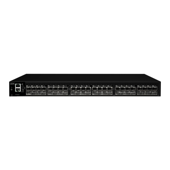
Page 29: Port Side Of The Switch
LEDs USB port Switch ID pull-out tab FC ports 0-3 (all LEDs Serial console port above) FC ports 40-43 System power LED Note: The two LEDs on the serial console port are nonfunctional. Chapter 1. Introducing the SAN48B-5... -
Page 30: Nonport Side Of The Switch
Figure 2 shows the non-port side of the switch, which contains the combination power supply / fan assemblies. These assemblies include the AC power receptacle and AC power switch. Figure 2. Non-port side of the switch Power supply/fan Power supply/fan assembly #1 assembly #2 SAN48B-5 Installation, Service, and User Guide... -
Page 31: Chapter 2. Installing And Configuring The Switch
IBM Quality Hotline toll-free 1-800-442-6773 or direct dial in other locations: 770-858-8459. v The SAN48B-5 switch, containing two integrated power and fan assemblies v 16 Gbps or 8 Gbps SFP+ modules for the Fibre Channel ports (speed and... -
Page 32: Site Preparation And Installation Requirements
Airflow and temperature requirements are met on an ongoing basis, particularly if the switch is installed in a closed or multicabinet assembly. v The additional weight of the switch does not exceed the cabinet’s weight limits or unbalance the cabinet in any way. SAN48B-5 Installation, Service, and User Guide... -
Page 33: Planning For Cable Management
Items required for installation The following items are required for installing, configuring and connecting the SAN48B-5 for use in a network and fabric: v Workstation with an installed terminal emulator, such as HyperTerminal. v Unused IP address and corresponding subnet mask and gateway address... - Page 34 Do not connect the switch to the network until the IP address is correctly set. For instructions on how to cable and configure the switch, and how to set the IP address, see “Configuring the switch” on page 14. SAN48B-5 Installation, Service, and User Guide...
-
Page 35: Installing In An Eia Cabinet
Installing in an EIA cabinet Attention: Refer to “Safety notices and labels” on page xiii before starting any installation procedure. Attention: Refer to “Rack safety” on page xix for danger and caution notices related to rack and cabinet installations. Time required Allow 15 to 30 minutes to complete this procedure. -
Page 36: Installation Instructions
2. Insert two 8-32 x 5/16 in. screws 3 into one of the pairs of vertically aligned holes in the bracket and then into the pair of holes on the side of the switch. To SAN48B-5 Installation, Service, and User Guide... -
Page 37: Position The Front Bracket
install the switch in a recessed position in the cabinet, use the bracket holes that are set back from the end of the bracket. 3. Insert each 8-32 x 5/16 in. screw through the holes in the bracket and into the corresponding hole in the switch and tighten all 8-32 x 5/16 in. -
Page 38: Position The Switch In The Cabinet
3. Adjust the brackets to cabinet depth and tighten the screws to a torque of 9 in-lb (10 cm-kg). 4. Repeat step 1 through step 3 to attach the left rear bracket 3 to the left front bracket. Figure 6. Position the rear and front brackets SAN48B-5 Installation, Service, and User Guide... - Page 39 Attaching the rear brackets to the cabinet rails Complete the following steps to attach the rear brackets to the cabinet rails. 1. Attach the right rear bracket 2 to the right rear cabinet rail using two 10-32 x 5/8 in. screws 4 and two retainer nuts 3 , as shown in Figure 7. 2.
-
Page 40: Configuring The Switch
Configuring the switch Once you have set up the SAN48B-5 in a rack or as a standalone switch, it is time to give it power and a basic configuration. If you are going to use the SAN48B-5 in a single-switch setup, you can use EZSwitchSetup to complete the basic configuration. -
Page 41: Setting The Switch Ip Address
/dev/ttya -9600 Setting the switch IP address You can configure the SAN48B-5 with a static IP address, or you can use a DHCP (Dynamic Host Configuration Protocol) server to set the IP address of the switch. DHCP is enabled by default. The SAN48B-5 supports both IPv4 and IPv6. -
Page 42: Setting The Switch Date And Time
Setting the switch date and time The SAN48B-5 maintains the current date and time inside a battery-backed real-time clock (RTC) circuit. The date and time settings are used for logging events. Switch operation does not depend on the date and time; a switch with an incorrect date and time value still functions properly. -
Page 43: Setting The Date
Local time synchronization You can synchronize the local time of the principal or primary fabric configuration server (FCS) switch to a maximum of eight external network time protocol (NTP) servers. To keep the time in your SAN current, it is recommended that the principal or primary FCS switch has its time synchronized with at least one external NTP server. -
Page 44: Setting The Time Zone
The principal or primary FCS switch synchronizes its time with the NTP server every 64 seconds. switch:admin> tsclockserver LOCL switch:admin> tsclockserver "132.163.135.131" switch:admin> tsclockserver 132.163.135.131 switch:admin> The following example shows how to set up more than one NTP server using a DNS name: SAN48B-5 Installation, Service, and User Guide... -
Page 45: Inter-Switch Link (Isl) Trunking
ISL Trunking is optional software that allows you to create trunking group of ISLs between adjacent switches. Up to eight FC ports on the SAN48B-5 can be used as a trunking group to achieve speeds up to 128 Gbps (256 Gbps full duplex) for optimal bandwidth utilization and load balancing. -
Page 46: Installing A 16 Gbps Sfp+ With Pull Tab (Shown Without Cable Attached)
Gbps SFP+ in the correctly oriented position on the port, as shown in Figure 9 on page 21. 3. Slide the SFP+ into the port until you feel it click into place; then close the bail. SAN48B-5 Installation, Service, and User Guide... -
Page 47: Fabric Os Native And Access Gateway Modes
Fabric OS Native and Access Gateway modes The SAN48B-5 can function in either Fabric OS Native mode or Access Gateway mode. The switch is shipped in Fabric OS Native mode by default. v You can enable Access Gateway mode using Fabric OS commands or Web Tools. -
Page 48: Disabling And Enabling Access Gateway Mode
Access Gateway or Fabric OS Native mode. For a list of available features for each mode, refer to the Access Gateway Administrator’s Guide. v In Access Gateway mode, cascading is not available for the SAN48B-5. Refer to the latest Access Gateway Administrator’s Guide for details on any other restrictions specific to the SAN48B-5. - Page 49 v Access Gateway Mode displays for switchMode if the switch is in Access Gateway mode. v Native displays for switchMode if the switch is in Fabric OS Native mode. 3. Enter switchDisable to disable the switch. Access Gateway mode can only be enabled or disabled when the switch is in a disabled state.
- Page 50 SAN48B-5 Installation, Service, and User Guide...
-
Page 51: Chapter 3. Using And Maintaining The Switch
“Interpreting LEDs” v “POST and boot specifications” on page 28 v “Interpreting POST results” on page 29 v “SAN48B-5 maintenance” on page 29 v “SAN48B-5 management” on page 30 Powering the switch on and off Complete the following steps to power the switch on. -
Page 52: Port Side Leds
Note: The two LEDs on the serial console port are nonfunctional. The non-port side of the switch has two power supply/fan assembly status LEDs (see Figure 12). Figure 12. Non-port side LEDs 1 Power supply/fan assembly #2 status 2 Power supply/fan assembly #1 status SAN48B-5 Installation, Service, and User Guide... -
Page 53: Port Side Led Patterns During Normal
Fast blinking Port failure. Check the management interface and amber (1/2 sec) the error log for details on the cause of the failure. Contact IBM Support if necessary. Steady green Online. No action required. Slow blinking Online but segmented (loopback cable No action required. -
Page 54: Post And Boot Specifications
3. Analyzes fabric. If any ports are connected to other switches, the switch participates in a fabric configuration. 4. Obtains a domain ID and assigns port addresses. 5. Constructs unicast routing tables. 6. Enables normal port operation. SAN48B-5 Installation, Service, and User Guide... -
Page 55: Interpreting Post Results
Fabric OS Message Reference Manual. SAN48B-5 maintenance The SAN48B-5 is designed for high availability and low failure; it does not require any regular physical maintenance. It includes diagnostic tests and field-replaceable units, described in the following sections. -
Page 56: San48B-5 Management
SAN48B-5 management You can use the management functions built into the SAN48B-5 to monitor the fabric topology, port status, physical status, and other information to help you analyze switch performance and to accelerate system debugging. The switch automatically performs power-on self-test (POST) each time it is turned on. -
Page 57: Chapter 4. Fru Replacement
Replacing a power supply and fan assembly The SAN48B-5 fans are fixed inside the combined power supply and fan FRU to provide necessary airflow to cool the whole system. There are two fans located in each FRU. -
Page 58: Switch Power Supply And Fan Assemblies On The Non-Port Side
Time Awake: 0 days (output truncated) The SAN48B-5 has two power supply and fan assemblies, as shown in Figure 14. Fabric OS identifies the assemblies from right to left on the non-port side as assembly 1 and assembly 2. (The actual appearance of the switch may differ from this illustration but the locations are correct.) -
Page 59: Determining The Need To Replace A Power Supply And Fan Assembly
Table 7. Power supply and fan assembly status LED behavior (continued) LED color Description Action required Steady green Power supply and fan assembly is No action is required. operating normally. Flashing green Power supply and fan assembly is Check the power cable connection. (for more than faulty for one of the following Verify that the assembly is powered... -
Page 60: Replacing A Power Supply And Fan Assembly
6. Note the part number and airflow label 4 on the assembly just removed. Replacing a power supply and fan assembly Refer to Figure 15 for this procedure. Complete the following steps to replace a combined power supply and fan assembly in the switch SAN48B-5 Installation, Service, and User Guide... -
Page 61: Removing The Battery
Repair or disassemble Exchange only with the IBM-approved part. Recycle or discard the battery as instructed by local regulations. In the United States, IBM has a process for the collection of this battery. For information, call 1-800-426-4333. Have the IBM part number for the battery unit available when you call. -
Page 62: Location Of Battery Holder
Figure 16. Location of battery holder 6. Recycle the battery as appropriate. Refer to the Environmental Notices and User Guide shipped with the product for more information on battery recycling and disposal. SAN48B-5 Installation, Service, and User Guide... -
Page 63: Appendix A. Product Specifications
Appendix A. Product specifications This appendix provides the specifications for the SAN48B-5 switch. v “Weight and physical dimensions” v “Facility requirements” v “Power supply specifications” on page 38 v “Environmental requirements” on page 38 v “General specifications” on page 39 v “Data transmission ranges”... -
Page 64: Power Supply Specifications
Acceptable range during non-operation Ambient 0° to +40°C (32° to 104°F) -25° to 70°C (-13° to 158°F) temperature Humidity 10% to 85% RH non-condensing, at 40°C 10% to 90% RH non-condensing, (104°F), at 70°C (158°F) SAN48B-5 Installation, Service, and User Guide... -
Page 65: General Specifications
Table 11. Environmental requirements (continued) Condition Acceptable range during operation Acceptable range during non-operation Altitude 0 to 3 km (9,842 ft) above sea level 0 to 12 km (39,370 ft) above sea level Shock 20 G, 6 ms, half-sine wave 33 G, 11 ms, half-sine wave, 3/eg Axis Vibration... -
Page 66: Data Transmission Ranges
The size of each is listed in Table 14. Table 14. Memory specifications Memory type Amount Boot flash 4 MB Compact flash 1 GB Main memory (DDR2 SDRAM) 1 GB, 64-bit with 8-bit ECC SAN48B-5 Installation, Service, and User Guide... -
Page 67: Fibre Channel Port Specifications
Fibre Channel port specifications The Fibre Channel ports in the SAN48B-5 are compatible with SWL, LWL, and ELWL SFP+ (for 16 Gbps performance) transceivers. The strength of the signal is determined by the type of transceiver in use. The ports meet all required safety standards. For more information about these standards, see “Electronic emission notices”... -
Page 68: Access Gateway Default Port Mapping
0-39 40-47 0-4 mapped to 40 5-9 mapped to 41 10-14 mapped to 42 15-19 mapped to 43 20-24 mapped to 44 25-29 mapped to 45 30-34 mapped to 46 35-39 mapped to 47 SAN48B-5 Installation, Service, and User Guide... -
Page 69: Appendix B. Link Troubleshooting
Appendix B. Link troubleshooting IBM SAN b-type directors and switches use the latest high bandwidth Fibre Channel technology and auto-negotiate to 16 Gbps, 8 Gbps, 4 Gbps, or 2 Gbps based on the link data rate capability of the attached transceiver and the speed supported by the switches and directors. -
Page 70: Dust, Dirt, Or Other Contaminants
Match the cable type with the wavelength, bandwidth, and distance to be supported; do not mix cable types within a link. v Inspect loss ratings of all cabling components during the selection process. v Record loss measurements for horizontal and vertical cable runs during installation. SAN48B-5 Installation, Service, and User Guide... -
Page 71: Attenuation On Lwl Connections
LWL transceivers or use of 8 Gbps LWL transceivers that employ rate select. 2G LWL SFP maximum receive power The IBM SAN b-type 8 Gbps and 16 Gbps directors and switches use the latest high bandwidth Fibre Channel technology and auto-negotiate to 16 Gbps, 8 Gbps, 4 Gbps, or 2 Gbps based on the link data rate capability of the attached transceiver. - Page 72 Optoway SPS-9110AFG 2 Gbps 10 km SFP -3 dB | | | | JDSU JSH-21L3AR3 2 Gbps 10 km SFP 1 dB | | | | ES212-LP3TA 2 Gbps 10 km SFP -3 dB SAN48B-5 Installation, Service, and User Guide...
-
Page 73: Notices
Consult your local IBM representative for information on the products and services currently available in your area. Any reference to an IBM product, program, or service is not intended to state or imply that only that IBM product, program, or service may be used. Any functionally equivalent product, program, or service that does not infringe on any IBM intellectual property right may be used instead. - Page 74 Information concerning non-IBM products was obtained from the suppliers of those products, their published announcements or other publicly available sources. IBM has not tested those products and cannot confirm the accuracy of performance, compatibility or any other claims related to non-IBM products.
-
Page 75: Trademarks
International Business Machines Corporation in the United States, other countries, or both. A complete and current list of other IBM trademarks is available on the Web at www.ibm.com/legal/copytrade.shtml Adobe, the Adobe logo, PostScript, and the PostScript logo are either registered trademarks or trademarks of Adobe Systems Incorporated in the United States, and/or other countries. -
Page 76: Electronic Emission Notices
Properly shielded and grounded cables and connectors must be used in order to meet FCC emission limits. IBM is not responsible for any radio or television interference caused by using other than recommended cables and connectors or by unauthorized changes or modifications to this equipment. -
Page 77: Germany Electromagnetic Compatibility Directive
Klasse A ein. Um dieses sicherzustellen, sind die Geräte wie in den Handbüchern beschrieben zu installieren und zu betreiben. Des Weiteren dürfen auch nur von der IBM empfohlene Kabel angeschlossen werden. IBM übernimmt keine Verantwortung für die Einhaltung der Schutzanforderungen, wenn das Produkt ohne Zustimmung der IBM verändert bzw. -
Page 78: People's Republic Of China Class A Electronic Emission Statement
Korea Communications Commission (KCC) Class A Statement Please note that this equipment has obtained EMC registration for commercial use. In the event that it has been mistakenly sold or purchased, please exchange it for equipment certified for home use. SAN48B-5 Installation, Service, and User Guide... -
Page 79: Russia Electromagnetic Interference (Emi) Class A Statement
Russia Electromagnetic Interference (EMI) Class A Statement Australia and New Zealand Class A Statement Attention: This is a Class A product. In a domestic environment this product might cause radio interference in which case the user might be required to take adequate measures. - Page 80 SAN48B-5 Installation, Service, and User Guide...
-
Page 81: Index
47 documentation rack-mount kit 10 safety xiii Brocade xxiii SFP/SFP+ 19 types xiii Fabric Operating System (FOS) xxiii switch 5 NTP time synchronization 17, 18 IBM xxiii intellectual property 47 © Copyright IBM Corp. 2011, 2013... - Page 82 35 setting 16 requirements synchronization 17, 18 cabinet 37 time zone electrical 37 setting 16 environmental 38 trademarks 49 thermal 37 USB port 3 safety labels xiii notices xiii rack xix, xx SAN48B-5 Installation, Service, and User Guide...
- Page 84 Part Number: 98Y5384 Printed in USA GA32-0895-03...