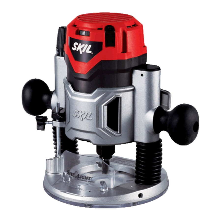
Skil 1817 Operating And Safety Instructions Manual
Fix base router
Hide thumbs
Also See for 1817:
- Operating instructions manual (56 pages) ,
- Operating/safety instructions manual (56 pages)
Advertisement
Advertisement
Table of Contents

Summary of Contents for Skil 1817
- Page 1 IMPORTANT: Read Before Using Operating/Safety Instructions 1817 1827 1830...
-
Page 2: Save All Warnings And Instructions For Future Reference
General Power Tool Safety Warnings Read all safety warnings and all instructions. Failure to follow the WARNING warnings and instructions may result in electric shock, fire and/or serious injury. SAVE ALL WARNINGS AND INSTRUCTIONS FOR FUTURE REFERENCE The term “power tool” in the warnings refers to your mains-operated (corded) power tool or battery-operated (cordless) power tool. - Page 3 Disconnect the plug from the power source Keep cutting tools sharp and clean. Properly and/or the battery pack from the power tool maintained cutting tools with sharp cutting before making any adjustments, changing edges are less likely to bind and are easier to accessories, or storing power tools.
-
Page 4: Additional Safety Warnings
Certain cleaning agents such as gasoline, to filter out microscopic particles. carbon tetrachloride, ammonia, etc. may damage plastic parts. Risk of injury to user. The power cord must only be serviced by a Skil Factory Service Center or Authorized Skil Service Station. - Page 5 Symbols IMPORTANT: Some of the following symbols may be used on your tool. Please study them and learn their meaning. Proper interpretation of these symbols will allow you to operate the tool better and safer. Symbol Name Designation/Explanation Volts Voltage (potential) Amperes Current Hertz...
- Page 6 Symbols (continued) IMPORTANT: Some of the following symbols may be used on your tool. Please study them and learn their meaning. Proper interpretation of these symbols will allow you to operate the tool better and safer. This symbol designates that this tool is listed by Underwriters Laboratories. This symbol designates that this tool is recognized by Underwriters Laboratories.
-
Page 7: Functional Description And Specifications
Functional Description and Specifications Disconnect the plug from the power source before making any WARNING assembly, adjustments or changing accessories. Such preventive safety measures reduce the risk of starting the tool accidentally. Fix Base Router FIG. 1 VENTILATION OPENINGS 2-POSITION SLIDE "ON/OFF"... - Page 8 Amperage rating 9.5A No load speed 25,000/min 10,500-25,000/min 10,500-25,000/min Collet capacities 1/4", 1/2" 1/4", 1/2" 1/4", 1/2" On models 1817, 1827 & 1830 router motor unit must be used with either fixed base type A, or plunge base Type B.
-
Page 9: Installing A Router Bit
Assembly A wide assortment of router bits with different collet wrench to firmly tighten the collet nut profiles is available separately. in a clockwise direction (viewed from under the router). To ensure proper gripping of the To prevent personal injury, WARNING router bit, the shank of the router bit must be always remove the plug... - Page 10 COLLET CHUCK ASSEMBLY COLLET CHUCK CARE All router models are designed to accept 1/2" and 1/4" shank bits. 1/4" shank bits require a 1/4" adapter sleeve. With the router bit 1/2" COLLET FIG. 6 removed, continue to turn the collet nut counter- CHUCK clockwise until it is loose.
- Page 11 DEFLECTOR CHIP DEFLECTOR Operating Instructions Skil routers are designed for speed, accuracy (Note that one full turn of the knob will raise or and convenience in performing cabinet work, lower the bit approximately 1/16" of an inch.) routing, fluting, beading, cove-cutting, dove After making depth adjustments, re-clamp the tails, etc.
- Page 12 DEPTH ADJUSTMENT WITH PLUNGE contacts the lowest step of the turret. Slide BASE PLUNGING ACTION the depth indicator until the line indicator The plunge feature simplifies depth points to zero on the depth scale, indicating adjustments and will allow the cutting bit to the point at which the bit just contacts the easily and accurately enter the workpiece.
- Page 13 2-POSITION SLIDE "ON/OFF" SWITCH SITE-LIGHT™ The tool can be switched "ON" by the 2- Your tool is also equipped with a Site-Light™ position slide switch located on the upper and for better visibility during operation. lower right side of the motor (Fig. 1). When the tool is plugged in, the lights will turn on automatically.
- Page 14 The router may stall if improperly used or Always use router bits with the shortest overloaded. Reduce the feed rate to prevent cutting length necessary to produce the possible damage to the tool. desired cut. This will minimize router bit run- out and chatter.
-
Page 15: Template Guides
FIG. 17 PILOT TIPPED AND BEARING GUIDE BITS The lower portion of a pilot tipped bit, as shown in (Fig. 17), is a shaft with no cutting edges. Bearing guide bits have a ball bearing to pilot the bit. This pilot slides along the edge of the work as the rotating blades make the cut, forming molding or decorative edges. -
Page 16: Maintenance
Skil Factory Service Center or Authorized Skil Service Station. BEARINGS After about 300-400 hours of operation, or at TOOL LUBRICATION... -
Page 17: Extension Cords
load or very abrasive material cutting) should Ventilation openings and switch levers must be replaced at once to avoid overheating or be kept clean and free of foreign matter. Do motor failure. not attempt to clean by inserting pointed objects through openings. Cleaning Certain cleaning agents To avoid accidents always... -
Page 18: Troubleshooting
Authorized Skil Service Center or Service Station.) 3. Inspect cord for damage. If damaged, have cord replaced by an Authorized Skil Service Center or Service Station.


