Table of Contents
Advertisement
Quick Links
GIGABYTE GA-8SIMLFS P4 Titan-DDR Motherbo
http://www.manuallib.com/file/2596474
From ManualLib.com
ManualLib.com collects and classifies the global product
instrunction manuals to help users access anytime and
anywhere, helping users make better use of products.
Home: http://www.manuallib.com/ Chinese: http://www.shuomingshuku.com/
This Manual: http://www.manuallib.com/file/2596474
Advertisement
Table of Contents

Related Manuals for Gigabyte GA-8SIMLFS


Summary of Contents for Gigabyte GA-8SIMLFS
- Page 1 GIGABYTE GA-8SIMLFS P4 Titan-DDR Motherbo http://www.manuallib.com/file/2596474 From ManualLib.com ManualLib.com collects and classifies the global product instrunction manuals to help users access anytime and anywhere, helping users make better use of products. Home: http://www.manuallib.com/ Chinese: http://www.shuomingshuku.com/ This Manual: http://www.manuallib.com/file/2596474...
- Page 2 GA-8SIMLFS P4 Titan-DDR Motherboard USER’S MANUAL Pentium 4 Processor Motherboard ® Rev 2001 This Manual: http://www.manuallib.com/file/2596474...
-
Page 3: Table Of Contents
Table of Content WARNING! ....................3 Chapter 1 Introduction ................4 Features Summary ..................4 GA-8SIMLFS Motherboard Layout ............. 6 Chapter 2 Hardware Installation Process ..........7 Step 1: Install the Central Processing Unit (CPU)........8 Step 1-1 : CPU Installation............8 Step 1-2 : CPU Heat Sink Installation ......... -
Page 4: Warning
WARNING! Computer motherboards and expansion cards contain very delicate Integrated Circuit (IC) chips. To protect them against damage from static electricity, you should follow some precautions whenever you work on your computer. Unplug your computer when working on the inside. Use a grounded wrist strap before handling computer components. -
Page 5: Chapter 1 Introduction
1 Serial port (COMA),1 VGA port,COMB on board 4 USB ports (Rear USB x 2,by optional cable) 1 Front Audio Connector 1 Serial IRQ Connector 1 IrDA connector for IR to be continued..GA-8SIMLFS Motherboard - 4 - This Manual: http://www.manuallib.com/file/2596474... - Page 6 Hardware Monitor CPU/System Fan Revolution detect CPU/System Fan Control CPU Overheat Warning System Voltage Detect On-Board Sound AC97 CODEC Line In/Line Out/Mic In/CD In /Game Port On-Board LAN Builit in RTL8100L Chipset 1 RJ45 port On-Board VGA Builit in SiS650GX Chipset PS/2 Connector PS/2 Keyboard interface and PS/2 Mouse interace BIOS...
-
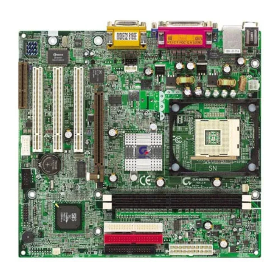
Page 7: Ga-8Simlfs Motherboard Layout
GA-8SIMLFS Motherboard Layout GA-8SIMLFS Motherboard - 6 - This Manual: http://www.manuallib.com/file/2596474... -
Page 8: Chapter 2 Hardware Installation Process
Chapter 2 Hardware Installation Process To set up your computer, you must complete the following steps: Step 1- Install the Central Processing Unit (CPU) Step 2- Install memory modules Step 3- Install expansion cards Step 4- Connect ribbon cables, cabinet wires, and power supply Step 5- Setup BIOS software Step 6- Install supporting software tools Step1... -
Page 9: Step 1: Install The Central Processing Unit (Cpu)
Please make sure the CPU type is supported by the motherboard. If you do not match the CPU socket Pin 1 and CPU cut edge well, it will cause improper installation. Please change the insert orientation. GA-8SIMLFS Motherboard - 8 - This Manual: http://www.manuallib.com/file/2596474... -
Page 10: Step 1-2: Cpu Heat Sink Installation
Step 1-2: CPU Heat Sink Installation 2. Hook the other end of the 1. Hook one end of the cooler cooler bracket to the CPU bracket to the CPU socket first. socket. Please use Intel approved cooling fan. We recommend you to apply the thermal tape to provide better heat conduction between your CPU and heatsink. -
Page 11: Step 2: Install Memory Modules
DIMM module. Please note that the DIMM module can only fit in one direction due to the one notches. Wrong orientation will cause improper installation. Please change the insert orientation. GA-8SIMLFS Motherboard - 10 - This Manual: http://www.manuallib.com/file/2596474... -
Page 12: Step 3: Install Expansion Cards
DDR Introduction Established on the existing SDRAM industry infrastructure, DDR (Double Data Rate) memory is a high performance and cost-effective solution that allows easy adoption for memory vendors, OEMs and system integrators. DDR memory is a sensible evolutionary solution for the PC industry that builds on the existing SDRAM infrastructure, yet makes awesome advances in solving the system performance bottleneck by doubling the memory bandwidth. -
Page 13: Step 4: Connect Ribbon Cables, Cabinet Wires, And Power Supply
SP 6) supports USB controller. If your OS does not support USB controller, please contact OS vendor for possible patch or driver upgrade. For more information please contact your OS or device(s) vendors. GA-8SIMLFS Motherboard - 12 - This Manual: http://www.manuallib.com/file/2596474... - Page 14 Parallel Port , Serial Port and VGA Port (LPT/COMA/VGA) Parallel Port (25 pin Female) This connector supports 1 standard COM port ,1 Parallel port and 1 VGA port. Device like printer can be connected to Parallel port ; mouse and modem etc can be connected to Serial ports. COMA Serial Port VGA Port...
-
Page 15: Step4-2: Connectors Introduction
Step4-2: Connectors Introduction A) ATX_12V K) F_USB B) CPU_FAN L) BATTERY C) ATX M) COMB D) PWR_FAN N) F_AUDIO E) FDD/IDE1/IDE2 O) CD_IN F) IR G) CLR_CMOS H) SYS_FAN I) CI J) F_PANEL GA-8SIMLFS Motherboard - 14 - This Manual: http://www.manuallib.com/file/2596474... - Page 16 A) ATX_12V ( +12V Power Connector) This connector (ATX +12V) suppliesthe CPU operation voltage (Vcore). If this " ATX+ 12V connector" is not connected, system cannot boot. +12V +12V B ) CPU_FAN (CPU FAN Connector) Please note, a proper installation of the CPU cooler is essential to prevent the CPU from running under abnormal condition or damaged by overheating.The CPU fan connector...
- Page 17 CD-R CD-L CAUTION Danger of explosion if battery is incorrectly replaced. Replace only with the same or equivalent type recommended by the manufacturer. Dispose of used batteries according to the manufacturer’s instructions. GA-8SIMLFS Motherboard - 16 - This Manual: http://www.manuallib.com/file/2596474...
- Page 18 C ) ATX (ATX Power) AC power cord should only be connected to your power supply unit after ATX power cable and other related devices are firmly +12V 5V SB (Stand by +5V) connected to the mainboard. Power Good PS-ON(Soft On/Off) 3.3V -12V 3.3V...
- Page 19 M ) COM B VCC(+5V) IR Data Input IR Data Output Be careful with the polarity of the IR connectorwhile you connect the IR. Please contact you nearest dealer for optional IR device. GA-8SIMLFS Motherboard - 18 - This Manual: http://www.manuallib.com/file/2596474...
-
Page 20: F_Panel
J) F_PANEL (2x7 pins jumper) HD (IDE Hard Disk Active LED) Pin 1: LED anode(+) Pin 2: LED cathode(-) SPK (Speaker Connector) Pin 1: VCC(+) Pin 2- Pin 3: NC Pin 4: Data(-) RST (Reset Switch) Open: Normal Operation Close: Reset Hardware System PD+/PD_G-/PD_Y-(Power LED) Pin 1: LED anode(+) Pin 2: LED cathode(-) Pin 3: LED cathode(-) -
Page 21: Entering Setup
Chapter 3 BIOS Setup BIOS Setup is an overview of the BIOS Setup Program. The program that allows users to modify the basic system configuration. This type of information is stored in battery-backed CMOS RAM so that it retains the Setup information when the power is turned off. ENTERING SETUP Power ON the computer and press <Del>... -
Page 22: Getting Help
The Main Menu (For example: BIOS Ver. :FC) If you want detail data setting before “BIOS ver FC“, please download the manual from Gigabyte web http://www.gigabyte.com.tw. Once you enter Award BIOS CMOS Setup Utility, the Main Menu (Figure 1) will appear on the screen. - Page 23 Integrated Peripherals This setup page includes all onboard peripherals. Power Management Setup This setup page includes all the items of Green function features. PnP/PCI Configurations This setup page includes all the configurations of PCI & PnP ISA resources. PC Health Status This setup page is the System auto detect Temperature, voltage, fan, speed.
- Page 24 Standard CMOS Features CMOS Setup Utility-Copyright (C) 1984-2002 Award Software Standard CMOS Features Date (mm:dd:yy) Fir, Jan 25 2002 Item Help Time (hh:mm:ss) 22:31:24 Menu Level Change the day, month, IDE Primary Master [None] year and century IDE Primary Slave [None] IDE Secondary Master [None]...
- Page 25 Time The times format in <hour> <minute> <second>. The time is calculated base on the 24-hour military- time clock. For example, 1 p.m. is 13:00:00. IDE Primary Master, Slave / IDE Secondary Master, Slave The category identifies the types of hard disk from drive C to F that has been installed in the computer. There are two types: auto type, and manual type.
-
Page 26: Base Memory
Floppy 3 Mode Support (for Japan Area) Disabled Normal Floppy Drive. (Default value) Drive A Drive A is 3 mode Floppy Drive. Drive B Drive B is 3 mode Floppy Drive. Both Drive A & B are 3 mode Floppy Drives. Halt on The category determines whether the computer will stop if an error is detected during power up. - Page 27 Advanced BIOS Features CMOS Setup Utility-Copyright (C) 1984-2002 Award Software Advanced BIOS Features BIOS Flash Protection [Auto] Item Help First Boot Device [Floppy] Menu Level Second Boot Device [HDD-0] [Auto] Third Boot Device [CDROM] Allows BIOS to Boot Up Floppy Seek [Disabled] update flash data BootUp Num-Lock...
-
Page 28: Boot Up Floppy Seek
LS120 Select your boot device priority by LS120. HDD-0~3 Select your boot device priority by HDD-0~3. SCSI Select your boot device priority by SCSI. CDROM Select your boot device priority by CDROM. Select your boot device priority by ZIP. USB-FDD Select your boot device priority by USB-FDD. -
Page 29: Full Screen Logo Show
Setup The system will boot, but access to Setup will be denied if the correct password is not entered at the prompt. (Default value) Interrupt Mode APIC Through IOAPIC generate more IRQ for system use.(Default value) Use AT stantard IRQ controlles to generate IRQ. When you already have IOAPIC enable system and want to upgrade the system please note, since running an IOAPIC enabled OS (like Windows NT,Windows 2000, Windows XP...) system with none IOAPIC HW support will cause the system to hang. - Page 30 Advanced Chipset Features We would not suggest you change the chipset default setting unless you really need it. CMOS Setup Utility-Copyright (C) 1984-2002 Award Software Advanced Chipset Features Item Help Configure DRAM Timing [Auto] Menu Level x CAS Latency Setting Auto x DRAM RAS Active Time x DRAM RAS Precharge Time...
-
Page 31: Dram Ras To Cas Delay
Set DRAM RAS Active Time to 6T. (Default value) Set DRAM RAS Active Time to 7T. DRAM RAS Precharge Time This feature allows you to set the DRAM RAS# Precharge Time. Set DRAM RAS Precharge Time to 2T. Set DRAM RAS Precharge Time to 3T. (Default value) Set DRAM RAS Precharge Time to 4T. - Page 32 Integrated Peripherals CMOS Setup Utility-Copyright (C) 1984-2002 Award Software Integrated Peripherals IDE1 Conductor Cable [Auto] Item Help IDE2 Conductor Cable [Auto] Menu Level On-Chip Primary PCI IDE [Enabled] [Auto] On-Chip Secondary PCI IDE [Enabled] Auto-detect IDE AC97 Audio [Enabled] cable type AC97 Modem [Enabled] System share Memory Size...
-
Page 33: Ac97 Audio
IDE1 Conductor Cable Auto Will be automatically detected by BIOS. (Default Value) ATA66/100 Set IDE1 Conductor Cable to ATA66/100 (Please make sure your IDE device and cable is compatible with ATA66/100). ATA33 Set IDE1 Conductor Cable to ATA33 (Please make sure your IDE device and cable is compatible with ATA33). -
Page 34: Usb Controller
Share Memory Size 4MB/8MB/16MB/32MB/64MB Set onchip VGA shared memory size.(Default Value:32MB) USB Controller Disable this option if you are not using the onboard USB feature. Enabled Enable USB Controller. (Default value) Disabled Disable USB Controller. USB Legacy Support Enabled Enable USB Legacy Support. Disabled Disable this function.(Default Value) Onboard Lan... -
Page 35: Onboard Parallel Port
Onboard Serial Port B Auto BIOS will automatically setup the port B address. 3F8/IRQ4 Enable onboard Serial port B and using daddress 3F8 , IRQ4. 2F8/IRQ3 Enable onboard Serial port B and using daddress 2F8 , IRQ3. (Default Value) 3E8/IRQ4 Enable onboard Serial port B and using daddress 3E8 , IRQ4. - Page 36 Parallel Port DMA This feature allows you to select Direct Memory Access(DMA) channel if the ECP mode selected. Set Parallel Port DMA to 3.(Default Value) Set Parallel Port DMA to 1. OnBoard Game Port This feature allows you to select the game port address or disable it. Disabled Disable OnBoard Game Port.
-
Page 37: Modem Use Irq
Power Management Setup CMOS Setup Utility-Copyright (C) 1984-2002 Award Software Power Management Setup ACPI Suspend Type [S1(POS)] Item Help MODEM Use IRQ [AUTO] Menu Level Soft-Off by Power Button [Off] System After AC Back [Off] IRQ [3-7, 9-15], NMI [Enabled] ModemRingOn/WakeOnLan [Enabled] PME Event Wake Up... - Page 38 Set MODEM Use IRQ to 9. Set MODEM Use IRQ to 10. Set MODEM Use IRQ to 11. Soft-off by Power Button The user press the power button once, he can turn off the system. (Default Value) Suspend The user press the power button once, then he can enter suspend mode. System after AC Back Last State When AC-power back to the system, the system will return to the Last state...
-
Page 39: Resume By Alarm
USB Device Wake-up From S3 When set at Enabled, it allows USB Device to activate the system from ACPI S3 power saving mode. Enabled Enable USB Device Wakeup. Disabled Disable USB Device Wakeup. (Default Value) Power On by Keyboard Password Input password (from 1 to 8 characters) and press Enter to set the Keyboard Power On Password. -
Page 40: Resources Controlled By
PnP/PCI Configurations CMOS Setup Utility-Copyright (C) 1984-2002 Award Software PnP/PCI Configurations Resources Controlled By [Auto] Item Help IRQ Resources Press Enter Menu Level PCI1 IRQ Assignment [Auto] [Auto] PCI2 IRQ Assignment [Auto] Assign PnP resource PCI3 IRQ Assignment [Auto] (I/O address, IRQ & DMA channels) for Plug and Play compatible devices automatically... - Page 41 PCI1 IRQ Assignment Auto Auto assign IRQ to PCI1. (Default value) 3,4,5,7,9,10,11,12,14,15 Set IRQ 3,4,5,7,9,10,11,12,14,15 to PCI4. PCI2 IRQ Assignment Auto Auto assign IRQ to PCI2. (Default value) 3,4,5,7,9,10,11,12,14,15 Set IRQ 3,4,5,7,9,10,11,12,14,15 to PCI1/5. PCI3 IRQ Assignment Auto Auto assign IRQ to PCI3. (Default value) 3,4,5,7,9,10,11,12,14,15 Set IRQ 3,4,5,7,9,10,11,12,14,15 to PCI2/6.
-
Page 42: Current System Temperature
PC Health Status CMOS Setup Utility-Copyright (C) 1984-2001 Award Software PC Health Status Item Help Menu Level VCORE 1.71V +3.3V 3.29V 4.99V +12V 11.73V Current System Temp. 27°C/ 80°F Current CPU Temperature 25°C/ 77°F Current CPU FAN Speed 4821 RPM Current System FAN Speed 0 RPM CPU Warning Temperature... -
Page 43: Cpu Warning Temperature
Current CPU Fan / System Fan Fan Speed (RPM) Detect Fan speed status automatically. CPU Warning Temperature 60°C / 140°F Monitor CPU Temp. at 60°C / 140°F. 70°C / 158°F Monitor CPU Temp. at 70°C / 158°F. 80°C / 176°F Monitor CPU Temp. at 80°C / 176°F. 90°C / 194°F Monitor CPU Temp. - Page 44 Load Fail-Safe Defaults CMOS Setup Utility-Copyright (C) 1984-2002 Award Software Standard CMOS Features Frequency/Voltage Control Advanced BIOS Features Load Fail-Safe Defaults Advanced Chipset Features Load Optimized Defaults Integrated Peripherals Set Supervisor Password Power Management Setup Set User Password PnP/PCI Configurations Load Fail-Safe Defaults? (Y/N)?Y Save &...
- Page 45 Load Optimized Defaults CMOS Setup Utility-Copyright (C) 1984-2002 Award Software Standard CMOS Features Frequency/Voltage Control Advanced BIOS Features Load Fail-Safe Defaults Advanced Chipset Features Load Optimized Defaults Integrated Peripherals Set Supervisor Password Power Management Setup Set User Password PnP/PCI Configurations Save &...
- Page 46 Set Supervisor/User Password CMOS Setup Utility-Copyright (C) 1984-2002 Award Software Standard CMOS Features Frequency/Voltage Control Advanced BIOS Features Load Fail-Safe Defaults Advanced Chipset Features Load Optimized Defaults Integrated Peripherals Set Supervisor Password Power Management Setup Set User Password PnP/PCI Configurations Save &...
- Page 47 Save & Exit Setup CMOS Setup Utility-Copyright (C) 1984-2002 Award Software Standard CMOS Features Frequency/Voltage Control Advanced BIOS Features Load Fail-Safe Defaults Advanced Chipset Features Load Optimized Defaults Integrated Peripherals Set Supervisor Password Power Management Setup Set User Password PnP/PCI Configurations Save &...
- Page 48 Exit Without Saving CMOS Setup Utility-Copyright (C) 1984-2002 Award Software Standard CMOS Features Frequency/Voltage Control Advanced BIOS Features Load Fail-Safe Defaults Advanced Chipset Features Load Optimized Defaults Integrated Peripherals Set Supervisor Password Power Management Setup Set User Password PnP/PCI Configurations Save &...