Philips CDR775 Service Manual
Hide thumbs
Also See for CDR775:
- Service manual (74 pages) ,
- Instructions for use manual (35 pages) ,
- Owner's manual (31 pages)
Advertisement
Quick Links
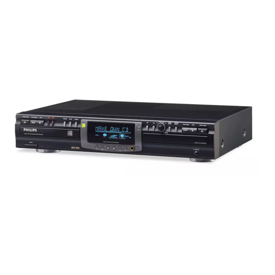
Compact disc recorder
CDR775
Service
/oo
nCOJJPACT
riBOMfWCT
nOOMPACT
HCOMPACT
t o g l ( t a oEt a scB
GQD§(S
SERVICING
For servicing CDR775, the set can divided into three parts.
1. The display board (partly) 1 002, the I/O board 1004, the
headphone board (partly) 1002, the IR board (partly) 1002, the ON/
OFF & Standby LED board (partly) 1002 and the CD-out board
(partly) 1002 have to be repaired at component level. The power
supply unit 1003 is available as spare part, but can also be repaired
at component level.
2.
The CDR module (containing the CDR loader 81, CDR main board
1001 and loader bracket 82, 83) will be exchanged completely in
case of failure. This complete CDR module is available as spare
part. Defective modules have to be returned for central repair.
3. The CD module (containing the CD loader 131, CD main board
1005 and loader bracket 132) is a new module with VAL1250
loader assy but also a separate CDM and separate loader parts will
be available via service stock. The CD main board can be repaired
at component level.
Also available: Circuit Description " The Basics of Compact Disc
Recordable/Rewriteable". Service code number 4822 725 25242.
Copyright reserved 1999 Philips Consumer Electronics B.V. Eindhoven, The
Netherlands. All rights reserved. No part of this publication may be reproduced,
stored in a retrieval system or transmitted, in any form or by any means, electronic,
mechanical, photocopying, or otherwise without the prior permission of Philips.
MOfTAlAUOtO
M B t T A l AUDIO
PtGfTAlAUMO
OHHTAL AUDIO
Contents
1. Technical Specifications
2. Warning and Servicing Hints
3. User Instructions
4.
Mechanical Instructions
Wiring Diagram CDR
Wiring Diagram CD loader
Exploded View CDR
Exploded View CD loader
Dismantling Instructions
5. Electrical and Circuit Diagrams
Overall Blockdiagram
Display Board
IR / On/Off &Standby LED Board
Headphone / CD-out Board
I/O Board
Power supply unit
CD-Mainboard 1A
CD-Mainboard 1B
CD-Mainboard 1C
CD-Mainboard 2
6. Diagnostic Software
7. Faultfinding Trees
8. Faultfinding Guide
9. List of Abbreviations
10. Partslist (mechanical and electrical)
Page
2
4
7
19
19
20
21
22
23
Diagram
PWB
24
26
27
28
29
31
33
34
35
36
39
43
49
65
71
26
27
28
30
32
37/38
37/38
37/38
37/38
Published by RH 9969 Service DPS Hasselt
Printed in the Netherlands
Subject to modification
<§§> 3104 125 40030
PHILIPS
Advertisement


