Table of Contents
Advertisement
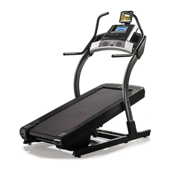
Model No. NETL18716.0
Serial No.
Write the serial number in the space
above for reference.
CUSTOMER SERVICE
UNITED KINGDOM
Call: 0330 123 1045
From Ireland: 053 92 36102
Website: www.iconsupport.eu
E-mail: csuk@iconeurope.com
Write:
ICON Health & Fitness, Ltd.
Unit 1D, The Gateway
Fryers Way, Silkwood Park
OSSETT
WF5 9TJ
UNITED KINGDOM
AUSTRALIA
Call: 1800 993 770
E-mail: australiacc@iconfitness.com
Write:
ICON Health & Fitness
PO Box 635
WINSTON HILLS NSW 2153
AUSTRALIA
CAUTION
Read all precautions and instruc-
tions in this manual before using
this equipment. Save this manual
for future reference.
Serial
Number
Decal
USER'S MANUAL
www.iconeurope.com
Advertisement
Table of Contents

Related Manuals for NordicTrack X7i


Summary of Contents for NordicTrack X7i
- Page 1 Model No. NETL18716.0 USER’S MANUAL Serial No. Write the serial number in the space above for reference. Serial Number Decal CUSTOMER SERVICE UNITED KINGDOM Call: 0330 123 1045 From Ireland: 053 92 36102 Website: www.iconsupport.eu E-mail: csuk@iconeurope.com Write: ICON Health & Fitness, Ltd. Unit 1D, The Gateway Fryers Way, Silkwood Park OSSETT...
-
Page 2: Table Of Contents
U.S. and other countries. Google Maps and Google Play are trademarks of Google Inc. The BLUETOOTH ® word mark and logos are registered trademarks of Bluetooth SIG, Inc. and are used under license. NORDICTRACK is a registered trademark of ICON Health & Fitness, Inc. 271317... -
Page 3: Important Precautions
IMPORTANT PRECAUTIONS WARNING: To reduce the risk of burns, fire, electric shock, or injury to persons, read all important precautions and instructions in this manual and all warnings on your incline trainer before using your incline trainer. ICON assumes no responsibility for personal injury or property damage sustained by or through the use of this product. - Page 4 20. Keep fingers, hair, and clothing away from 25. Never insert any object into any opening on the moving walking belt. the incline trainer. 21. The incline trainer is capable of high speeds. 26. Inspect and properly tighten all parts each Adjust the speed in small increments to time the incline trainer is used.
-
Page 5: Before You Begin
Thank you for selecting the revolutionary reading this manual, please see the front cover of this NORDICTRACK X7I INCLINE TRAINER. The X7I manual. To help us assist you, note the product model ® INCLINE TRAINER offers a selection of features number and serial number before contacting us. -
Page 6: Part Identification Chart
PART IDENTIFICATION CHART Use the drawings below to identify small parts used for assembly. The number in parentheses below each draw- ing is the key number of the part, from the PART LIST near the end of this manual. The number following the key number is the quantity used for assembly. -
Page 7: Assembly
ASSEMBLY • Assembly requires two persons. • To identify small parts, see page 6. • Place all parts in a cleared area and remove the • Assembly requires the following tools: packing materials. Do not dispose of the packing materials until you finish all assembly steps. the included hex keys •... - Page 8 3. Remove the four 3/8" x 2 3/4" Screws (22) from the Uprights (83). Save the Screws. 4. Set the Uprights (83) on the Base (74). Make sure that the hole with the Upright Wire (75) is on the right side. Attach the right Upright (83) to the Base (74) with two of the 3/8"...
- Page 9 6. Identify the right handrail assembly (C). Hold the right handrail assembly near the right side of the console assembly (D), and connect the two pulse wires (E). Next, set the right handrail assembly (C) on the console assembly (D). Make sure that no wires are pinched.
- Page 10 8. Press the two tabs on the Tablet Holder (65) into the slots (G) in the console assembly (D). Attach the Tablet Holder (65) with four #8 x 5/8" Machine Screws (8). Tip: Start the two top Start First Machine Screws first, and then start the two bottom Machine Screws.
-
Page 11: The Chest Heart Rate Monitor
THE CHEST HEART RATE MONITOR HOW TO PUT ON THE HEART RATE MONITOR • Store the heart rate monitor in a warm, dry place. Do not store the heart rate monitor in a plastic bag or If the heart rate monitor looks like the one shown other container that may trap moisture. -
Page 12: How To Use The Incline Trainer
HOW TO USE THE INCLINE TRAINER HOW TO PLUG IN THE POWER CORD Follow the steps below to plug in the power cord. This product must be earthed. If it should malfunc- 1. Plug the indicated end of the power cord into the tion or break down, earthing provides a path of least socket on the incline trainer. - Page 13 CONSOLE DIAGRAM FEATURES OF THE CONSOLE To turn on the power, see page 14. To use the man- ual mode, see page 14. To use an onboard workout, The incline trainer console offers a selection of fea- see page 16. To connect your smart device to the console, see page 18.
- Page 14 HOW TO TURN ON THE POWER HOW TO USE THE MANUAL MODE IMPORTANT: If the incline trainer has been 1. Insert the key into the console. exposed to cold temperatures, allow it to warm to room temperature before you turn on the power. If See HOW TO TURN ON THE POWER at the left.
- Page 15 4. Change the incline of the incline trainer as The My Trail tab will show a track that represents desired. 400 m (1/4 mile). As you exercise, the flashing rectangle will show your progress. The My Trail tab To change the incline of the incline trainer, press will also show the number of laps you complete.
- Page 16 8. When you are finished exercising, remove the Before using the handgrip key from the console. heart rate monitor, Step onto the foot rails, press the Stop button, and adjust the incline of the incline trainer to zero. remove the sheets of The incline must be at zero or you may damage plastic from...
- Page 17 3. Start the workout. Note: The calorie goal is an estimate of the number of calories that you will burn during Press the Start button or the Speed increase but- the workout. The actual number of calories that you burn will depend on various factors ton to start the workout.
- Page 18 HOW TO CONNECT YOUR SMART DEVICE TO THE HOW TO CONNECT YOUR HEART RATE MONITOR CONSOLE TO THE CONSOLE The console supports BLUETOOTH connections to The console is compatible with all BLUETOOTH Smart smart devices via the iFit app and to compatible heart heart rate monitors.
- Page 19 THE SETTINGS MODE HOW TO USE THE TABLET HOLDER The console features a settings mode that keeps track IMPORTANT: The tablet holder is designed for use with most full-size tablets. Do not place any other of incline trainer information and allows you to person- electronic device or object in the tablet holder.
-
Page 20: How To Move The Incline Trainer
HOW TO MOVE THE INCLINE TRAINER Before moving the incline trainer, insert the key Carefully roll the incline trainer on the wheels to the into the console, adjust the incline level to zero, desired location, and then lower it to the level position. remove the key, and unplug the power cord. -
Page 21: Maintenance And Troubleshooting
MAINTENANCE AND TROUBLESHOOTING MAINTENANCE c. Check the power switch located on the incline trainer frame near the power cord. If the switch pro- Regular maintenance is important for optimal perfor- trudes as shown, the switch has tripped. To reset mance and to reduce wear. Inspect and properly tighten the power switch, wait for five minutes and then all parts each time the incline trainer is used. - Page 22 SYMPTOM: The console does not display speed b. If the walking belt is overtightened, incline trainer and distance correctly performance may decrease and the walking belt may become damaged. First, adjust the incline to a. Remove the key from the console and UNPLUG 40 percent.
- Page 23 SYMPTOM: The walking belt is not centered SYMPTOM: The incline of the incline trainer does between the foot rails not change correctly a. Hold down the Stop button and the Speed increase a. IMPORTANT: If the walking belt rubs against button, insert the key into the console, and then the foot rails, the walking belt may become release the Stop button and the Speed increase...
-
Page 24: Exercise Guidelines
EXERCISE GUIDELINES Burning Fat—To burn fat effectively, you must exer- WARNING: cise at a low intensity level for a sustained period of Before beginning this time. During the first few minutes of exercise, your or any exercise program, consult your physi- body uses carbohydrate calories for energy. -
Page 25: Part List
PART LIST Model No. NETL18716.0 R0516A Key No. Qty. Description Key No. Qty. Description 3/8" x 5 1/2" Screw Cushion Cap 3/8" x 3 3/4" Screw Spring 3/8" Star Washer Cushion #8 x 3/4" Tek Screw Base Wire #8 x 3/4" Screw Rubber Cushion 3/8"... - Page 26 Key No. Qty. Description Key No. Qty. Description #8 Nut Filter Magnet #8 x 3/4" Clip Screw Reed Switch 1/4" x 1 1/2" Screw Reed Switch Clip 1/4" x 2" Screw Motor Isolator #8 x 3/4" Ground Screw Motor Bushing –...
-
Page 27: Exploded Drawing
EXPLODED DRAWING A Model No. NETL18716.0 R0516A... - Page 28 EXPLODED DRAWING B Model No. NETL18716.0 R0516A...
- Page 29 EXPLODED DRAWING C Model No. NETL18716.0 R0516A...
- Page 30 EXPLODED DRAWING D Model No. NETL18716.0 R0516A...
- Page 31 EXPLODED DRAWING E Model No. NETL18716.0 R0516A...
-
Page 32: Ordering Replacement Parts
ORDERING REPLACEMENT PARTS To order replacement parts, please see the front cover of this manual. To help us assist you, be prepared to provide the following information when contacting us: • the model number and serial number of the product (see the front cover of this manual) •...