Table of Contents
Advertisement
Quick Links
32 Bit / 768 kHz
Hi-Res Audio
SteadyClock
2 Channels Analog / Digital Converter
4 Channels Digital / Analog Converter
2 Extreme Power Headphone Outputs
User's Guide
ADI-2 Pro
Conversion done right
™
III
AES / ADAT / SPDIF Interface
32 Bit / 768 kHz Digital Audio
USB 2.0 Class Compliant
Digital Signal Processing
Advanced Feature Set
™
SyncCheck
Advertisement
Table of Contents

Related Manuals for RME Audio ADI-2 Pro


Summary of Contents for RME Audio ADI-2 Pro
- Page 1 User’s Guide ADI-2 Pro Conversion done right 32 Bit / 768 kHz Hi-Res Audio ™ ™ SyncCheck SteadyClock 2 Channels Analog / Digital Converter 4 Channels Digital / Analog Converter AES / ADAT / SPDIF Interface 32 Bit / 768 kHz Digital Audio USB 2.0 Class Compliant...
-
Page 2: Table Of Contents
14.1 Options 14.1.1 Hardware/Diagnosis........25 14.1.2 Clock ............25 14.1.3 Device Mode ..........26 14.2 Load/Store all Settings .........27 Meter Screens 15.1 Global Level Meter ..........27 15.2 Analyzer ...............28 15.3 State Overview.............28 15.4 Dark Volume ............29 Warning Messages..........30 User’s Guide ADI-2 Pro © RME... - Page 3 25.5 ASIO ..............51 DIGICheck Windows..........52 Installation and Operation – Mac OS X General..............54 27.1 Configuring the ADI-2 Pro........54 27.2 Clock Modes - Synchronization ......55 27.3 Multi-interface Operation ........55 DIGICheck Mac............55 User’s Guide ADI-2 Pro © RME...
- Page 4 34.11 Loudness..............74 34.12 Total Harmonic Distortion Measurements ...75 34.13 Extreme Power Charts .........76 34.14 Phones Distortion Measurements......77 34.15 Impedance based Level Meters PH 1-4 ....77 Miscellaneous Accessories .............80 Warranty..............80 Appendix ..............81 Declaration of Conformity ........82 User’s Guide ADI-2 Pro © RME...
-
Page 5: General
Here it is – the ADI-2 Pro, the little wonder, a host of devices all put together into one unit, with a simple and mostly automated way of using it right out of the box: •... -
Page 6: Brief Description And Characteristics
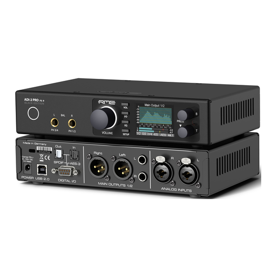
4. Brief Description and Characteristics The ADI-2 Pro is a 2-channel analog input to digital and 4-channel digital to analog output con- verter in a half-rack (9.5") enclosure of 1 U height. Latest 32 bit / 768 kHz converters offer up to 124 dBA signal to noise ratio. -
Page 7: First Usage - Quick Start
AES I/O via XLR and SPDIF coaxial I/O via RCA. The ADI-2 Pro has two analog line inputs that can operate with levels up to +24 dBu. The elec- tronic input stage uses a servo balanced design which handles unbalanced and balanced sig- nals correctly, automatically adjusting the level reference. -
Page 8: Quick Start
EQ is disabled. The EQ can be enabled in the second menu which comes up by push- ing the EQ key a second time. *(shown by a 1 beside the current channel. Turning encoder 1 will change to the EQ settings of the other channels) User’s Guide ADI-2 Pro © RME... -
Page 9: Overview Menu Structure
1 or 2 whenever any of them is displayed. To quickly call them up simply press any of the 4 buttons several times. In all level meter screens turning encoder 1 and 2 brings up the quick access to Bass and Treble, with +/- 6 dB maximum boost/cut. 5.4. Overview Menu Structure User’s Guide ADI-2 Pro © RME... -
Page 10: Playback
ADI-2 Pro. 5.7 Digital Recording The easiest way to perform digital recordings with the ADI-2 Pro is to set the SRC to the cur- rently used input (SPDIF or AES), then set the Clock to INT(ernal) and the desired sample rate –... -
Page 11: Power Supply
6. Power Supply In order to make operating the ADI-2 Pro as flexible as possible, the unit has a universal DC input socket, accepting voltages from 9.5 Volts up to 15 Volts. An internal switching regulator of the latest technology with high efficiency (> 90%) prevents internal hum noise by operating above audible frequencies. -
Page 12: Features Explained
For example when inserting the head- phone jack into Ph 3/4, the ADI-2 Pro activates the mute relay after half a second, then the DSP ramps up the volume slowly from lower level to the last used state. Comfortable? Luxurious? Yes, but the main reason for it was to give the user a chance to react. -
Page 13: Dual Phones Outputs
8.2 Dual Phones Outputs Many features and design decisions on the ADI-2 Pro come from personal usage and experi- ence. For example when comparing headphones: it turns out to be very difficult when having just one headphone output. Changing the phones on the head is already a disrupting process which hinders easy comparison, but without proper level adjustment first, and the need to un- plug one and to plug the other, comparisons are only possible for coarse differences. -
Page 14: Bass / Treble
In that mo- ment a quick turn on the two ADI-2 Pro’s small encoders will make the music sound perfect. These Bass and Treble controls are limited to ± 6 dB. Everything exceeding such values should be handled by the EQ, and/or calls for better speakers/phones. -
Page 15: Src (Sample Rate Conversion)
No matter how sensitive the connected phones or speakers are, no matter how much increase in Bass and Treble are desired – with the ADI-2 Pro one can finally adjust it to meet the per- sonal hearing and taste. Loudness finally works as it should have worked from the start - an- other unique feature in the ADI-2 Pro. -
Page 16: Dsp Limitations
There is never enough DSP power – no matter how much you add (frustrated developer). That is true even for the ADI-2 Pro. Although being equipped with a quite capable 2.17 Giga FLOPS DSP chip, plus using the FPGA to perform further calculations (RME’s virtual DSP for mixing/routing, level meters, filtering), 768 kHz sample rate takes its toll. -
Page 17: Basic And Stand-Alone Operation Details
User’s Guide ADI-2 Pro Basic and Stand-Alone Operation Details User’s Guide ADI-2 Pro © RME... -
Page 18: Operation And Usage
9. Operation and Usage General operation and usage of the ADI-2 Pro are explained in chapter 5.2, Quick Start, and chapter 5.3, Operation at the unit. The ADI-2 Pro ships with Basic Mode Auto activated. In this mode the unit will automatically... -
Page 19: Vol
Digital amplification of the input signal between 0 and +6 dB, in steps of 0.5 dB. Main use is to fine-tune the input sensitivity so that it matches the reference output level of external gear. User’s Guide ADI-2 Pro © RME... -
Page 20: Parametric Eq
Quality factor is adjustable from 0.5 to 5.0 in steps of 0.1. This equals a bandwidth setting of 2.54 to 0.29. Subpage Parametric EQ R is only shown with Dual EQ set to On. It has the exact same entries as listed above. User’s Guide ADI-2 Pro © RME... -
Page 21: Main Output
At moderate turning speed the changes in dB follow the intended volume change. Only at slower turning the finest steps will be used. User’s Guide ADI-2 Pro © RME... -
Page 22: Bass/Treble
-20 dB. Default: -30 dB. A volume setting below this point will have maximum Bass/Treble gain, all volume settings above this point will have lower Bass/Treble gain. 20 dB above the Low Vol Ref setting the Bass/Treble gain will be zero. User’s Guide ADI-2 Pro © RME... -
Page 23: Phones Output 3/4
This can be used to achieve more than 12 dB gain, or to generate difficult frequency response optimizations. Note: The ADI-2 Pro has an internal headroom of 24 dB. Extreme boosts with overlapping filters could cause an internal overload. Such an overload will be visible as it is displayed by the level meter below the EQ, as well as the channel’s level meter. - Page 24 Space, Aa to Zz, + - / ( ) * ; : . , ! # $ & < > = ' I @, 0 - 9 Save to Use encoder 2 to select the slot where the current preset should be stored to. To store press and hold encoder 2 for one second. User’s Guide ADI-2 Pro © RME...
-
Page 25: Setup
Available settings are: Off, AES In, SPDIF In Optical Out Available settings are: SPDIF, ADAT. While the ADI-2 Pro supports only channels 1/2, in spe- cific cases it might still be useful to transfer digital audio in ADAT format. While the input adapts to the received signal automatically, the output needs to be switched manually. -
Page 26: Device Mode
SPDIF, or received in case a signal of 192 kHz sample rate is attached. The reason is that the ADI-2 Pro includes a special SMUX mode. When run at Octa Speed, the ADI- 2 Pro will split the data of the left analog input channel to the AES/SPDIF output channels left and right, at half the sample rate –... -
Page 27: Load/Store All Settings
15. Meter Screens The ADI-2 Pro has 4 different meter screens: a global level meter that shows all signal levels of all I/Os simultaneously, an Analyzer showing the audio signal content on the analog inputs and both analog outputs 1/2 and 3/4, a state overview showing the digital states of AES, SPDIF and USB, and a dark Volume screen with comprehensive information. -
Page 28: Analyzer
15.2 Analyzer The Analyzer is one of the main features of the ADI-2 Pro. Thanks to the high-resolution IPS panel even smallest details are clear to see. Music content analysis is possible even when viewed from a greater distance. The Analyzer is based on RME’s famous Spectral Analyzer in DIGICheck. It uses 29 biquad bandpass filters for high separation between the bands, providing outstanding musical visuali- zation. -
Page 29: Dark Volume
The column SR shows the hardware measured sample rate for the SPDIF and AES input. It will even display values that can not be set at the ADI-2 Pro itself, for example 32, 64 and 128 kHz. In case of USB the sample rate is not measured but set by the external computer or iOS device, and can be verified here, up to the highest value of 768 kHz. -
Page 30: Warning Messages
16. Warning Messages The ADI-2 Pro will show different warning messages and provide guidance in certain cases. Hi-Power Mode Active When Hi-Power mode is active with the Volume set higher than -15 dB and a phone is plugged in, this message reminds... -
Page 31: Modes
The ADI-2 Pro also shows certain Info Messages during normal operation, to explain the cur- rent state and to point out possible problems. In AD/DA mode, a Non-Audio Channel Status causes the DA section to be muted. An info mes- sage Non-Audio signal at SPDIF input gives a hint why there is currently no analog audio at the outputs present. -
Page 32: Preamp
USB to the host. In multi-channel mode three separate stereo pairs, in stereo mode only the stereo analog input. USB Playback channels 3/4 can only be monitored in multi-channel mode. In stereo mode se- lecting USB 3/4 plays channels 1/2. User’s Guide ADI-2 Pro © RME... -
Page 33: Ad/Da Converter
USB to the host. In multi-channel mode three separate stereo pairs, in stereo mode only the stereo analog input. USB Playback channels 3/4 can only be monitored in multi-channel mode. In stereo mode se- lecting USB 3/4 plays channels 1/2. User’s Guide ADI-2 Pro © RME... -
Page 34: Usb
USB playback signal is available simultaneously at all analog and digital outputs. The two block diagrams show the small differences between both modes. USB Playback channels 3/4 can only be monitored in multi-channel mode. In stereo mode se- lecting USB 3/4 plays channels 1/2. User’s Guide ADI-2 Pro © RME... - Page 35 USB playback will feed all outputs separately (8 channels). In 6/8 channel mode all I/Os can be used separately. Phones output 3/4 provides USB playback of channels 1/2 when its Source is set to Auto (default). User’s Guide ADI-2 Pro © RME...
-
Page 36: Digital Through Mode
USB to the host. In multi-channel mode three separate stereo pairs, in stereo mode only the stereo analog input. USB Playback channels 3/4 can only be monitored in multi-channel mode. In stereo mode se- lecting USB 3/4 plays channels 1/2. User’s Guide ADI-2 Pro © RME... -
Page 37: Balanced Phones Mode
Quite popular is the use of a 4-pin XLR male connector on the phones side. The diagram to the right shows how an adapter cable can be used to connect the ADI-2 Pro phones outputs, using two stereo TRS plugs and one female XLR connector. -
Page 38: General
PCM data. Note that the data stays pure DSD and is NOT converted to PCM. The ADI-2 Pro supports DSD in various ways. When received via AES or SPDIF, the State Overview screen will show DoP, and the DAC immediately turns from PCM to DSD mode. The process is transparent to the user, playback will continue as usual. -
Page 39: Dsd Playback
DAC's click noise. 19.4 DSD Record The ADI-2 Pro converts the analog input data not only to PCM, but optionally also to DSD. Via I/O - Analog Input - AD Conversion the AD-converter can be switched from PCM (Default) to DSD. - Page 40 User’s Guide ADI-2 Pro © RME...
-
Page 41: Inputs And Outputs
User's Guide ADI-2 Pro Inputs and Outputs User’s Guide ADI-2 Pro © RME... -
Page 42: Analog Inputs
Trim Gain can also be used to increase the input sensitivity to -2 dBu for 0 dBFS. Note that digital gain reduces the basic signal to noise ratio of the ADI-2 Pro by the amount of the gain. In real-world applications this will hardly be any problem, as the worst case SNR of -112 dBu is very difficult to achieve from most analog sources. -
Page 43: Line Out Ts 1/2
Please note that PH 3/4 is the main phones output of the ADI-2 Pro. PH 1/2 is designed as ad- dition and extra functionality. Sharing volume/level settings with the rear outputs some limita- tions arise. -
Page 44: Ph Out 3/4
22. Digital Connections 22.1 AES The ADI-2 Pro provides one XLR AES/EBU input and output each via the included breakout cable when connected to the D-sub 9 pin socket on the back of the unit. Connection is accom- plished using balanced cables with XLR plugs. Input and Output are transformer-balanced and ground-free. -
Page 45: Spdif
Audio signals with Emphasis have a high frequency boost, requiring high frequency attenuation during playback. When using the ADI-2 Pro as audio interface to record SPDIF into an audio file, the emphasis state is lost. See chapter 34.4 for details. -
Page 46: Adat
Output With SPDIF identical signals are available at both the optical and the coaxial output. An obvious use for this would be to connect two devices, i.e. using the ADI-2 Pro as a splitter (distribution 1 on 2). Under Setup – Options – Hardware/Diagnosis – Optical Out the output format can be manually changed from SPDIF to ADAT. -
Page 47: Installation And Operation - Windows
User's Guide ADI-2 Pro Installation and Operation – Windows User’s Guide ADI-2 Pro © RME... -
Page 48: Driver Installation
• The USB cable is not, or not correctly inserted into the socket • Use the ADI-2 Pro State Overview screen to verify USB is detected and working (chapter 15.3) De-installing the Driver A de-installation of the driver files is not necessary. Thanks to full Plug & Play support, the driver files will not be loaded after the hardware has been removed. -
Page 49: Configuring The Adi-2 Pro
24. Configuring the ADI-2 Pro 24.1 Settings Dialog Configuration of the ADI-2 Pro is usually done directly at the unit. For ASIO operation sample rate and buffer size (latency) can be set via a dedicated settings dialog. The panel 'Settings' can... -
Page 50: Clock Modes - Synchronization
Note: Since Vista the audio application can no longer control the sample rate under WDM. Therefore the driver of the ADI-2 Pro includes a way to set the sample rate globally for all WDM devices, found within the Settings dialog. See chapter 24.1. -
Page 51: Dvd-Playback (Ac-3/Dts)
When using popular DVD software players, their audio data stream can be sent to any AC- 3/DTS capable receiver via the ADI-2 Pro. The sample rate must be set to 48 kHz in the ADI-2 Pro Settings dialog, or the software will only playback the down-mixed analog signal via SPDIF. -
Page 52: Asio
I/O when set to Stereo, 6 in / 8 out when set to Multi-channel. See chapter 14.1.3. Note: chang- ing the CC-Mode requires to temporarily disconnect the ADI-2 Pro from the computer. The ASIO 2.2 driver supports sample rates up to 768 kHz in PCM format. DSD record/playback uses DoP within ASIO as transfer format. -
Page 53: Installation And Operation - Mac Os X
User's Guide ADI-2 Pro Installation and Operation – Mac OS X User’s Guide ADI-2 Pro © RME... -
Page 54: General
27. General The ADI-2 Pro is a UAC 2.0 Class Compliant device. Mac OS X has full UAC support built-in, there is no driver installation required. Connect computer and ADI-2 Pro with a USB cable. Mac OS X detects the new hardware as ADI-2 Pro (serial number). -
Page 55: Clock Modes - Synchronization
Whenever several devices are linked within a system, there must always be a single master clock. A digital system can only have one master! If the ADI-2 Pro’s clock mode is set to 'Internal', all other devices must be set to ‘Slave’. - Page 56 User’s Guide ADI-2 Pro © RME...
-
Page 57: Installation And Operation - Ios
User's Guide ADI-2 Pro Installation and Operation – iOS User’s Guide ADI-2 Pro © RME... -
Page 58: General
/ set the sample rate to a desired value, but not all apps include a choice to select one. Setting the ADI-2 Pro (and with it the i-device) to slave mode by selecting the AES or SPDIF input as clock source, the ADI-2 Pro will be synchronized to the external digital sam- ple rate. -
Page 59: Technical Reference
User's Guide ADI-2 Pro Technical Reference User’s Guide ADI-2 Pro © RME... -
Page 60: Technical Specifications
• Signal to Noise ratio (SNR) @ +13/19 dBu: 117 dB RMS unweighted, 120 dBA • Signal to Noise ratio (SNR) @ +4 dBu: 113 dB RMS unweighted, 117 dBA • Output impedance: 100 Ohm User’s Guide ADI-2 Pro © RME... -
Page 61: Digital Inputs
SPDIF coaxial • 1 x RCA, transformer-balanced, according to IEC 60958 • High-sensitivity input stage (< 0.3 Vpp) • AES/EBU compatible (AES3-1992) SPDIF optical • 1 x optical, according to IEC 60958 • ADAT compatible User’s Guide ADI-2 Pro © RME... -
Page 62: Digital Outputs
• Dimensions (WxHxD): 215 x 44 x 130 mm (8.5" x 1.73" x 5.1") • Weight: 1.0 kg ( 2.2 lbs) • Temperature range: +5° up to +50° Celsius (41° F up to 122°F) • Relative humidity: < 75%, non condensing User’s Guide ADI-2 Pro © RME... -
Page 63: Connector Pinouts
An adapter cable as shown to the right gives balanced phones with 4-pin XLR connector access to the ADI-2 Pro outputs. Using mini XLRs the pinout (signal to pin number) is identical. User’s Guide ADI-2 Pro © RME... -
Page 64: Technical Background
PLL tracks the receiver's frequency. If an SPDIF signal is applied to the ADI-2 Pro, the State Overview screen shows LOCK, i. e. a valid input signal. Unfortunately, lock does not necessarily mean that the received signal is cor- rect with respect to the clock which processes the read out of the embedded data. -
Page 65: Latency And Monitoring
Low Latency The ADI-2 Pro uses the latest top AD- and DA-converters with special low latency filters, offer- ing exceptional signal to noise and distortion figures in combination with a super-fast conver- sion. A delay of down to 5 samples had been unavailable a few years back. The exact delays... -
Page 66: Balanced Phones Mode
• Output level is doubled. With the ADI-2 Pro +22 dBu would rise to +28 dBu (a gain of +6 dB). Now only few might have a headphone that requires that level, a scary 19.5 Volts in output voltage. - Page 67 The ADI-2 Pro deserves a different, better way to go balanced. The picture below shows RME’s exclusive design as implemented in the ADI-2 Pro. The ADI-2 Pro has two DACs and a powerful DSP. These ingredients allow for a much im- proved version with several advantages: •...
-
Page 68: Emphasis
The Advanced Balanced mode design does have one drawback though: it will work in DSD mode, but not in Direct DSD mode. With the ADI-2 Pro that is no real issue, as in Direct DSD mode phones are turned off anyway due to the missing volume control. -
Page 69: Noise Level In Hi-Speed Modes
34.5 Noise Levels in Hi-Speed Modes The outstanding signal to noise ratio of the ADI-2 Pro AD-converters can be verified even with- out expensive test equipment, by using record level meters of various software. But when acti- vating higher sample rates, the displayed noise level will rise from -120 dBFS to -114 dBFS at 96 kHz, and –92 dBFS at 192 kHz. -
Page 70: Steadyclock
It needs to be mentioned that the ADC used in the ADI-2 Pro has improved noise shaping fil- ters, adapted to the higher sample rate range that it offers. Indeed the rise in noise over fre- quency is much lower than in former converter chips, where for example at 192 kHz sample rate the wideband noise measurement would not reach -92 dBFS, but only -79 dBFS. - Page 71 The so called sampling jitter, usually in the range of a few picosec- onds, is also extremely low on the ADI-2 Pro. One way to show this is to feed a 10 kHz sine into the analog input, then analyze the sampled result in the digital domain.
-
Page 72: Ad Filter Curves
34.7 AD Filter Curves 34.8 DA Filter Curves User’s Guide ADI-2 Pro © RME... -
Page 73: Da Impulse Responses
DAC filter menu. Note that there is no audible distortion, the steps equal high frequency har- monics that are mostly higher than 20 kHz. Please also note that Slow and NOS filters cause much more aliasing into the audio band and out-of-band noise than Sharp filters. User’s Guide ADI-2 Pro © RME... -
Page 74: Frequency Response Measurements
34.10 Frequency Response Measurements 34.11 Loudness User’s Guide ADI-2 Pro © RME... -
Page 75: Total Harmonic Distortion Measurements
34.12 Total Harmonic Distortion Measurements User’s Guide ADI-2 Pro © RME... -
Page 76: Extreme Power Charts
34.13 Extreme Power Charts User’s Guide ADI-2 Pro © RME... -
Page 77: Phones Distortion Measurements
DAC. Above 32 Ohms the level meter's display matches the real analog output level (0 dBFS = +22 dBu). But at 32 Ohms the ADI-2 Pro delivers only +19 dBu, at 16 Ohms +15 dBu to the phones outputs, because a reasonable current limiting circuit prevents a too high output power at lower load impedances. - Page 78 User’s Guide ADI-2 Pro © RME...
-
Page 79: Miscellaneous
User's Guide ADI-2 Pro Miscellaneous User’s Guide ADI-2 Pro © RME... -
Page 80: Accessories
Audio AG does not accept claims for damages of any kind, especially consequential damage. Liability is limited to the value of the ADI-2 Pro. The general terms of business drawn up by Audio AG apply at all times. -
Page 81: Appendix
Worldwide distribution: Audio AG, Am Pfanderling 60, D-85778 Haimhausen, Tel.: (49) 08133 / 918170 Acknowledgements The Bauer Binaural Crossfeed effect in the ADI-2 Pro was inspired by Boris Mikhaylov’s bs2b implementation. Trademarks All trademarks, registered or otherwise, are the property of their respective owners. RME, DIGICheck and Hammerfall are registered trademarks of RME Intelligent Audio Solutions. -
Page 82: Declaration Of Conformity
Synthax United States, 6600 NW 16th Street, Suite 10, Ft Lauderdale, FL 33313 T.:754.206.4220 Trade Name: RME, Model Number: ADI-2 Pro This equipment has been tested and found to comply with the limits for a Class B digital device, pursuant to Part 15 of the FCC Rules.