Onkyo HT-RC160 Instruction Manual
80 watts/channel & 8 ohms
Hide thumbs
Also See for HT-RC160:
- Instruction manual (121 pages) ,
- Quick setup (2 pages) ,
- Service manual (112 pages)
Table of Contents
Advertisement
AV Receiver
HT-RC160
Instruction Manual
Thank you for purchasing an Onkyo AV Receiver.
Please read this manual thoroughly before making
connections and plugging in the unit.
Following the instructions in this manual will enable
you to obtain optimum performance and listening
enjoyment from your new AV Receiver.
Please retain this manual for future reference.
Contents
Introduction ...................................2
Connection ..................................15
Turning On & First Time Setup .....37
Basic Operations.........................50
Using the Listening Modes ........59
Advanced Setup ..........................66
Zone 2
.........................................82
Controlling Other Components ....86
Others...........................................97
E
n
Advertisement
Table of Contents

Related Manuals for Onkyo HT-RC160


Summary of Contents for Onkyo HT-RC160
- Page 1 Advanced Setup ......66 Zone 2 .........82 Controlling Other Components ..86 Thank you for purchasing an Onkyo AV Receiver. Please read this manual thoroughly before making connections and plugging in the unit. Following the instructions in this manual will enable Others...........97 you to obtain optimum performance and listening enjoyment from your new AV Receiver.
-
Page 2: Important Safety Instructions
WARNING: WARNING AVIS RISK OF ELECTRIC SHOCK RISQUE DE CHOC ELECTRIQUE TO REDUCE THE RISK OF FIRE OR ELECTRIC DO NOT OPEN NE PAS OUVRIR SHOCK, DO NOT EXPOSE THIS APPARATUS TO The lightning flash with arrowhead symbol, within an RAIN OR MOISTURE. -
Page 3: Precautions
CET APPAREIL NUMÉRIQUE DE are wet or damp. If water or any other liquid gets LA CLASSE B EST CONFORME À LA NORME inside this unit, have it checked by your Onkyo NMB-003 DU CANADA. dealer. Sur les modèles dont la fiche est polarisée: 8. -
Page 4: Supplied Accessories
Supplied Accessories Make sure you have the following accessories: Remote controller & two batteries (AA/R6) Speaker setup microphone Indoor FM antenna AM loop antenna Speaker cable labels (not supplied with the HT-S7200 Home Theater Sys- tem.) In catalogs and on packaging, the letter at the end of the product name indicates the color. -
Page 5: Table Of Contents
Connecting an RI Dock ........35 Connecting a Dock with the Universal Port connector ... 35 Controlling Other Components Connecting Onkyo u Components ....36 Controlling Other Components........ 86 Connecting the Power Cord ........ 36 Preprogrammed Remote Control Codes ..... 86 Looking up for Remote Control Code .... -
Page 6: Features
HD Radio™ and the HD Radio Ready logo are proprietary trademarks of iBiquity Digital Corporation. • Bi-Amp Capability for Music and Movie Sound To receive HD Radio broadcasts, you must install an Onkyo Effects UP-HT1 HD Radio tuner module (sold separately). -
Page 7: Multiroom Capability
Multiroom Capability You can use two speaker systems with this AV receiver—a surround-sound speaker system (up to 7.1 channels) in your main listening room, a stereo speaker system in a second room, or Zone 2, as we call it. And, you can select a different audio source for each room. -
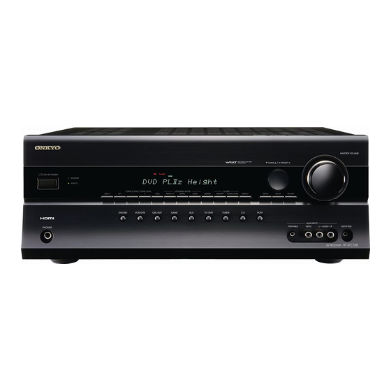
Page 8: Front & Rear Panels
Front & Rear Panels Front Panel d e f g h i j k l mn o p The actual front panel has various logos printed on it. They are not shown here for clarity. The page numbers in parentheses show where you can find the main explanation for each item. a ON/STANDBY button (37) i GAME button (59) This button is used to set the AV receiver to On or... -
Page 9: Display
Front & Rear Panels—Continued q MASTER VOLUME control (50) t AUX INPUT (32) This control is used to adjust the volume of the AV This input can be used to connect a camcorder, receiver to Min, 1 through 79 or Max. game console, and so on. -
Page 10: Rear Panel
This u (Remote Interactive) jack can be con- nections carry digital audio and digital video. nected to an u jack on another Onkyo AV compo- The HDMI inputs are for connecting components nent. The AV receiver’s remote controller can then with an HDMI output, such as a DVD/BD player, be used to control that component. - Page 11 Front & Rear Panels—Continued k CD IN This analog audio input is for connecting a CD player’s analog audio output. l TV/TAPE IN/OUT This analog audio input and output are for connect- ing a recorder with an analog audio input and output (cassette, Mini Disc, etc.).
-
Page 12: Remote Controller
• Don’t mix new and old batteries or different types of • When you want to operate an Onkyo component with batteries. u connection or an -compatible compo- •... -
Page 13: Controlling The Av Receiver
Also you can select a preset directly. a ON/STANDBY button (37) Sets the AV receiver to On or Standby. Note: An Onkyo cassette recorder connected via u can also b REMOTE MODE/INPUT SELECTOR buttons be controlled in Receiver mode (see page 96). (50, 90–96) Selects the remote controller modes and the input sources. -
Page 14: About Home Theater
With DVDs you can enjoy DTS and Dolby Digital. With analog or digital TV, you can enjoy Dolby Pro Logic IIx, DTS Neo:6, or Onkyo’s original DSP listening modes. -
Page 15: Connecting The Av Receiver
Connecting the AV Receiver • Speaker cable labels is not supplied with the Connecting Your Speakers HT-S7200 Home Theater System. • If you are using banana plugs, tighten the speaker ter- Speaker Configuration minal before inserting the banana plug. • Do not insert the speaker code directly into the center For 7.1-channel surround-sound playback, you need hole of the speaker terminal. - Page 16 Connecting the AV Receiver—Continued Connecting a Powered Subwoofer • Don’t connect more than one cable to each speaker terminal. Doing so may damage the AV receiver. Using a suitable cable, connect the AV receiver’s PRE • Don’t connect one speaker to several terminals. OUT: SUBWOOFER to an input on your powered sub- woofer, as shown.
- Page 17 Connecting the AV Receiver—Continued The following illustration shows which speaker should be connected to each pair of terminals. If you’re using only one surround back speaker, connect it to the left (L) SURR BACK SPEAKERS terminals. Surround Surround Surround Surround back left back right left...
-
Page 18: Bi-Amping The Front Speakers
Connecting the AV Receiver—Continued Bi-amping Speaker Hookup Bi-amping the Front Speakers The FRONT L/R and SURR BACK L/R terminal posts Connect the AV receiver’s FRONT R positive (+) can be used with front speakers and surround back terminal to the right speaker’s positive (+) Woofer speakers respectively, or bi-amped to provide separate (low) terminal. -
Page 19: Connecting Antenna
Connecting the AV Receiver—Continued Connecting the AM Loop Antenna Connecting Antenna The supplied indoor AM loop antenna is for indoor use This section explains how to connect the supplied indoor only. FM antenna and AM loop antenna, and how to connect commercially available outdoor FM and AM antennas. - Page 20 Connecting the AV Receiver—Continued Connecting an Outdoor FM Antenna Connecting an Outdoor AM Antenna If you cannot achieve good reception with the supplied If good reception cannot be achieved using the supplied indoor FM antenna, try a commercially available out- AM loop antenna, an outdoor AM antenna can be used door FM antenna instead.
-
Page 21: About Av Connections
Connecting the AV Receiver—Continued AV Connection Color Coding About AV Connections RCA-type AV connections are usually color-coded: red, • Before making any AV connections, read the manuals white, and yellow. Use red plugs to connect right-chan- supplied with your other AV components. nel audio inputs and outputs (typically labeled “R”). -
Page 22: Connecting Components With Hdmi
■ Onkyo for System Control , which stands for Remote Interactive over HDMI, is the name of the system control function found on Onkyo components. The AV receiver can be used with CEC (Consumer Electronics Control), which allows system control over HDMI and is part of the HDMI standard. -
Page 23: Video Signals
Connecting the AV Receiver—Continued Making HDMI Connections Step 1: Use HDMI cables to connect the AV receiver’s HDMI jacks to your HDMI-compatible Blu-ray player/DVD player, TV, projector, and so on. Step 2: Assign each HDMI IN to an input selector in the HDMI Input Setup (see page 39). ■... -
Page 24: Connecting Both Audio & Video
Connecting the AV Receiver—Continued Connecting Both Audio & Video By connecting both the audio and video outputs of your DVD/BD player and other AV components to the AV receiver, you can select both the audio and video simultaneously simply by selecting the appropriate input source on the AV receiver. - Page 25 Connecting the AV Receiver—Continued ■ Signal Selection If signals are present at more than one input, the DVD/BD player, etc. Signal Selection Example inputs will be selected automatically in the fol- lowing order of priority: HDMI, component video, composite video. Composite Component HDMI...
-
Page 26: Connecting A Tv Or Projector
Connecting the AV Receiver—Continued Connecting a TV or Projector See “Connecting Components with HDMI” on page 22 for HDMI connection information. Step 1: Video Connection Choose a video connection that matches your TV ( ), and then make the connection. Step 2: Audio Connection Choose an audio connection that matches your TV ( , , or... -
Page 27: Connecting A Dvd/Bd Player
Connecting the AV Receiver—Continued Connecting a DVD/BD Player See “Connecting Components with HDMI” on page 22 for HDMI connection information. Step 1: Video Connection Choose a video connection that matches your DVD/BD player ( , and then make the connection. You must connect the AV receiver to your TV via the same type of connection. -
Page 28: Connecting A Vcr Or Dvd/Bd Recorder For Playback
Connecting the AV Receiver—Continued Connecting a VCR or DVD/BD Recorder for Playback With this hookup, you can use your VCR’s tuner to listen to your favorite TV programs via the AV Hint! receiver, useful if your TV has no audio outputs. Step 1: Video Connection Choose a video connection that matches your VCR or DVD/BD recorder ( , and then make the connection. -
Page 29: Connecting A Vcr Or Dvd/Bd Recorder For Recording
Connecting the AV Receiver—Continued Connecting a VCR or DVD/BD Recorder for Recording Step 1: Video Connection Make the video connection . The video source to be recorded must be connected to the AV receiver via the same type of connection. Step 2: Audio Connection Make the audio connection Connection... -
Page 30: Connecting A Satellite, Cable, Terrestrial Set-Top Box, Or Other Video Source
Connecting the AV Receiver—Continued Connecting a Satellite, Cable, Terrestrial Set-top box, or Other Video Source With this hookup, you can use your satellite or cable receiver to listen to your favorite TV programs Hint! via the AV receiver, useful if your TV has no audio outputs. Step 1: Video Connection Choose a video connection that matches the video source ( , and then make the connection. -
Page 31: Connecting A Game Console
Connecting the AV Receiver—Continued Connecting a Game Console Step 1: Video Connection Choose a video connection that matches the game console ( , and then make the connection. You must connect the AV receiver to your TV with the same type of connection. Step 2: Audio Connection Choose an audio connection that matches the game console ( ), and then make the connection. -
Page 32: Connecting A Camcorder Or Other Device
Connecting the AV Receiver—Continued Connecting a Camcorder or Other Device Step 1: Video Connection Make the connection Step 2: Audio Connection Make the connection AUX INPUT AUX INPUT VIDEO AUDIO Camcorder, etc. VIDEO AUDIO Connection AV receiver Signal flow Camcorder etc. ⇐... -
Page 33: Connecting A Cd Player Or Turntable
Connecting the AV Receiver—Continued Connecting a CD Player or Turntable ■ CD Player or Turntable (MM) with Built-in Phono Preamp Step 1: Choose a connection that matches your CD player ( , , or ). Use connection for a turntable with a built-in phono preamp. -
Page 34: Connecting A Cassette, Cdr, Minidisc, Or Dat Recorder
Connecting the AV Receiver—Continued Connecting a Cassette, CDR, MiniDisc, or DAT Recorder Step 1: Choose a connection that matches the recorder ( , ), and then make the connection. OPTICAL (GAME) COAXIAL TV/TAPE (CBL/SAT) TV/TAPE Connect one or the other Cassette, CDR, MD, etc. -
Page 35: Connecting An Ri Dock
Connect your RI Dock’s audio output jacks to the AV receiver’s GAME IN or VCR/DVR IN L/R jacks, and connect its video output jack to the AV receiver’s GAME IN or VCR/DVR IN V jacks. (Onkyo DS-A2 TV/TAPE hookup shown below.) -
Page 36: Connecting Onkyo U Components
• Some components have two u jacks. You can con- nect either one to the AV receiver. The other jack is for connecting additional u-capable components. • Connect only Onkyo components to u jacks. Con- necting other manufacturer’s components may cause a malfunction. -
Page 37: Turning On The Av Receiver
If you have, see “HDMI Input Setup” on page 39, “Component Video Setup” on page 40, or “Digital Input Setup” on page 41 respectively. ■ Have you connected an Onkyo RI Dock? If you have, see “Changing the Input Display” on page 44. -
Page 38: First Time Setup
First Time Setup This section explains the settings that you need to make before using the AV receiver for the very first time. Using the Display to change the settings The settings of the AV receiver can be changed using the Display. -
Page 39: Video Input Setup
First Time Setup—Continued Use the Up and Down [q]/[w] but- Video Input Setup tons to select an input selector, and use the Left and Right [e]/ HDMI Input Setup [r] buttons to select: If you connect a video component to HDMI IN, you HDMI1, HDMI2, HDMI3, HDMI4, must assign that input to an input selector. - Page 40 First Time Setup—Continued Component Video Setup Use the Up and Down [q]/[w] but- tons to select an input selector, If you connect to a COMPONENT VIDEO IN, you must and then use the Left and Right assign it to an input selector. For example, if you connect [e]/[r] buttons to select: your DVD/BD player to COMPONENT VIDEO IN 2, IN1: Select if the video component...
-
Page 41: Digital Input Setup
First Time Setup—Continued Digital Input Setup Use the Up and Down [q]/[w] but- tons to select an input selector, If you connect a component to a digital input jack, you and use the Left and Right must assign that jack to an input selector. For example, if [e]/[r] buttons to select you connect your CD player to the OPTICAL IN1 jack, “COAX1”, “COAX2”, “OPT1”,... -
Page 42: Speaker Settings
First Time Setup—Continued Speaker Settings Use the Up and Down [q]/[w] but- tons to select “Speaker Type”, and then use the Left and Right If you change these settings, you must run the [e]/[r] buttons to select: Audyssey 2EQ™ Room Correction and Speaker Setup Normal: Select this if you’ve con- again (see page 45). -
Page 43: Fm/Am Frequency Step Setup
First Time Setup—Continued FM/AM Frequency Step Setup Press the [SETUP] button. The setup menu closes. For FM/AM tuning to work properly, you must specify the FM/AM frequency step used in your area. Note that when this setting is changed, all radio presets are deleted. -
Page 44: Changing The Input Display
Changing the Input Display • DOCK can be selected for the TV/TAPE or GAME or If you connect an u-capable Onkyo RI Dock to the VCR/DVR input selector, but not at the same time. • Enter the appropriate remote control code before TV/TAPE IN, GAME IN or VCR/DVR IN jacks, for u using the AV receiver’s remote controller for the first... -
Page 45: Audyssey 2Eq™ Room Correction And Speaker Setup
First Time Setup—Continued Measurement Positions Audyssey 2EQ™ Room Correction and Speaker Setup To create a listening environment in your home theater that all listeners will enjoy, Audyssey 2EQ takes With the supplied calibrated microphone, measurements at up to three positions within the Audyssey 2EQ automatically determines the number of listening area. - Page 46 First Time Setup—Continued Using Audyssey 2EQ™ Set the speaker setup micro- phone at the Main Listening Posi- ON/STANDBY tion (page 45), and connect it to the SETUP MIC jack. The speaker setting menu appears. 2EQ: Auto Setup Speaker Type Normal Powered Zone 2 Not Act Surr Back/Front High...
- Page 47 First Time Setup—Continued When prompted, place the setup • Make the room as quiet as possible. microphone at the next position, Background noise can disrupt the and repeat step 5. room measurements. Close windows, silence cell phones, When the measurements are televisions, radios, air conditioners, complete, the following screen fluorescent lights, home appliances,...
-
Page 48: Error Messages
First Time Setup—Continued ❏ Speaker Detect Error Disconnect the speaker setup This message appears if a speaker is not detected. “Yes” microphone. means that a speaker was detected. “No” means that no speaker was detected. 2EQ: Auto Setup 2EQ: Auto Setup Speaker Detect Error Please unplug setup microphone. - Page 49 This message appears if saving fails. Try saving again. If this message appears after 2 or 3 attempts, the AV receiver is probably malfunctioning. Contact your Onkyo dealer. Retry: Return to step 2 and try again. Cancel: Cancel the room correction and speaker setup.
-
Page 50: Basic Operations
Basic Operations Selecting the Input Source This section explains how to select the input source (i.e., the AV component that you want to listen to or watch). INPUT SELECTOR RECEIVER MASTER VOLUME VOL q/w INPUT SELECTOR Use the AV receiver’s input selector buttons to select the input source. -
Page 51: Adjusting The Bass & Treble
Basic Operations—Continued Displaying Source Information –, +, TONE You can display various information about the current input source as follows. Remote Press the [RECEIVER] button, controller and then press the [DISPLAY] button repeatedly to cycle through the available informa- tion. DISPLAY Press [RECEIVER]... -
Page 52: Muting The Av Receiver
Basic Operations—Continued Using the Sleep Timer Press With the sleep timer, you can set the AV receiver to turn [RECEIVER] off automatically after a specified period. first Press the [RECEIVER] button, MUTING and then press the [SLEEP] but- ton repeatedly to select the required sleep time. -
Page 53: Listening To The Radio
Listening to the Radio Using the Tuner FM STEREO AUTO With the built-in tuner you can enjoy AM and FM radio stations. You can store your favorite stations as presets for quick selection. TUNED TUNING MODE ■ Manual Tuning Mode Press the [TUNING MODE] but- ton so that the AUTO indicator disappears from the display. -
Page 54: Presetting Am/Fm Stations
Listening to the Radio—Continued Selecting Presets Presetting AM/FM Stations PRESET e/r MEMORY PRESET e/r AV receiver To select a preset, use the PRE- You can store a combination of up to 40 of your favorite SET [e]/[r] buttons, or the AM/FM radio stations as presets. -
Page 55: Up-A1 Series Dock For Ipod
Turning the adapter counterclockwise use the AV receiver’s remote controller to operate your moves it forward. Turning it clockwise moves it back- iPod. ward. For the latest information on the Dock, see the Onkyo Web site at: www.onkyo.com Forward Adapter Backward Notes: •... -
Page 56: Controlling Ipod
UP-A1 series Dock for iPod—Continued Operating Notes: Controlling iPod • Before selecting a different input source, stop iPod playback to prevent the AV receiver from selecting the By pressing the REMOTE MODE button that’s been iPod input source by mistake. programmed with the remote control code for your •... - Page 57 UP-A1 series Dock for iPod—Continued Status messages a Arrow [q]/[w] and ENTER buttons Used to navigate menus and select items. ❏ The AV receiver is checking the connection b Previous [7] button with the dock Restarts the current song. Press it twice to select the previous song.
-
Page 58: Recording
Recording This section explains how to record the selected input Recording Separate AV Sources source to a component with recording capability, and Here you can record audio and video from completely how to record audio and video from different sources. separate sources, allowing you to overdub audio onto Notes: your video recordings. -
Page 59: Using The Listening Modes
Using the Listening Modes Selecting with the Remote Controller Selecting Listening Modes See “About the Listening Modes” on page 64 for detailed information about the listening modes. MUSIC • The Dolby Digital and DTS listening modes can GAME only be selected if your DVD/BD player is con- MOVIE/TV STEREO nected to the AV receiver with a digital audio... -
Page 60: Listening Modes Available For Each Source Format
Using the Listening Modes—Continued Listening Modes Available for Each Source Format The Speaker layout illustration shows which Front high Front high speakers are set to active in the “Speaker Con- L Speaker R Speaker figuration” setting (see page 67) and the Front R Front L Speaker “Speaker Type”... - Page 61 Using the Listening Modes—Continued Stereo Source ✔: Available Listening Modes Speaker layout Listening Mode Button ✔ ✔ ✔ ✔ Direct ✔ ✔ ✔ ✔ Stereo ✔ ✔ ✔ ✔ Mono PLII/PLIIx ✔ ✔ ✔ (Surround Back) Movie PLII/PLIIx ✔ ✔ ✔...
- Page 62 Using the Listening Modes—Continued 5.1 channel Sources ✔: Available Listening Modes Speaker layout Listening Mode Button ✔ ✔ ✔ ✔ Direct ✔ ✔ ✔ ✔ Stereo ✔ ✔ ✔ ✔ Mono DolbyDigital/ DolbyDigital Plus/TrueHD/ Multichannel/ DTS/DTS-HD ✔ ✔ ✔ High Resolution Audio/DTS-HD Master Audio/...
- Page 63 Using the Listening Modes—Continued 7.1 channel Sources ✔: Available Listening Modes Speaker layout Listening Mode Button ✔ ✔ ✔ ✔ Direct (Surround Back) ✔ ✔ ✔ ✔ Stereo ✔ ✔ ✔ ✔ Mono Multichannel/ DolbyDigital Plus/TrueHD/ ✔ ✔ ✔ DTS-HD High (Surround Back) Resolution Audio/DTS-HD...
-
Page 64: About The Listening Modes
Using the Listening Modes—Continued 5.1-channel source + Dolby EX About the Listening Modes These modes expand 5.1-channel sources for 6.1/7.1- The AV receiver’s listening modes can transform your channel playback. They’re especially suited to Dolby EX listening room into a movie theater or concert hall, with soundtracks that include a matrix-encoded surround high fidelity and stunning surround sound. - Page 65 Using the Listening Modes—Continued DTS Neo:6 Onkyo Original DSP Modes This mode expands any 2-channel source for up to 7.1- Orchestra channel playback. It uses seven full-bandwidth channels Suitable for classical or operatic music, this mode of matrix decoding for matrix-encoded material, provid-...
-
Page 66: Advanced Setup
Advanced Setup Onscreen Setup Menus The onscreen setup menus appear on the connected TV and provide a convenient way to change the AV receiver’s various settings. Settings are organized into nine categories on the main menu, most containing a submenu. Main menu Submenus pages 39–41... -
Page 67: Common Procedures In Setup Menu
Advanced Setup—Continued Common Procedures in Setup Menu Press the [RECEIVER] button followed by the [SETUP] button. The main menu appears onscreen. If the main menu doesn’t appear, make sure the appropriate external input is selected on your TV. RECEIVER Use the Up and Down [q]/[w] buttons to select main menu, and then press qwer [ENTER]. - Page 68 Advanced Setup—Continued LPF of LFE 80Hz, 90Hz, 100Hz (default), 120Hz (Low-Pass Filter for the LFE Channel) This setting is not set automatically by the Audyssey 2EQ™ Room Correction and Speaker Setup function (see page 45). With this setting, you can specify the cutoff frequency of the LFE channel’s low-pass filter (LPF), which can be used to filter out unwanted hum.
- Page 69 Advanced Setup—Continued Level calibration This setting is set automatically by the Audyssey 2EQ™ Room Correction and Speaker Setup function (see page 45). Here you can adjust the level of each speaker with the built-in test tone so that the volume of each speaker is the same at the listening position.
-
Page 70: Audio Adjust
Advanced Setup—Continued Audio Adjust With the Audio Adjust functions and settings, you can adjust the sound and listening modes as you like. Multiplex/Mono Settings Multiplex Input Channel Main: The main channel is output (default). Sub: The sub channel is output. Main/Sub: Both the main and sub channels are output. - Page 71 Advanced Setup—Continued DTS Setting Neo:6 Music Center Image 0 to 5 (default: 2) The DTS Neo:6 Music listening mode creates 6-channel surround sound from 2-channel stereo sources. With this setting, you can specify by how much the front left and right channel output is attenuated in order to create the center channel.
-
Page 72: Using The Audio Settings
Advanced Setup—Continued Using the Audio Settings You can change various audio settings by pressing the [AUDIO] button. Note: When the “Audio TV Out” setting is set to “On” (page 78), the [AUDIO] button is disabled. Press the [RECEIVER] button followed by the [AUDIO] button. - Page 73 Advanced Setup—Continued CinemaFILTER With the CinemaFILTER, you can soften overly bright movie soundtracks, which are typically mixed for reproduction in a movie theater. CinemaFILTER can be used with the following listening modes: Dolby Digital, Dolby Digital EX, Dolby Digital Plus, TrueHD, Dolby Pro Logic IIx Movie, Dolby Pro Logic II Movie, Multichannel, DTS, DTS-ES, DTS Neo:6 Cinema, DTS 96/24, Neo:6, DTS-HD High Resolution, DTS-HD Master and DTS Express.
-
Page 74: Assigning Listening Modes To Input Sources
Advanced Setup—Continued Assigning Listening Modes to Input Use the Up and Down [q]/[w] buttons to select the signal format that you want to Sources set, and then use the Left and Right [e]/ You can assign a default listening mode to each input [r] buttons to select a listening mode. -
Page 75: Source Setup
Advanced Setup—Continued IntelliVolume Source Setup With IntelliVolume, you can set the input level for each This section explains items on the “Source Setup” menu. input selector individually. This is useful if one of your Items can be set individually for each input selector. source components is louder or quieter than the others. - Page 76 Advanced Setup—Continued Name Edit To correct a character: 1. Use the arrow [q]/[w]/[e]/[r] buttons to select You can enter a custom name for each individual input “ ” (Left) or “ ” (Right) and then press selector and radio preset for easy identification. When [ENTER].
-
Page 77: Miscellaneous (Volume/Osd) Setup
Advanced Setup—Continued Volume Setup Miscellaneous (Volume/OSD) Setup ■ Maximum Volume This section explains the items on the “Miscellaneous” menu. With this setting, you can limit the maximum volume. The Maximum Volume range is “Off”, 79 to 30. Press the [RECEIVER] button followed by ■... -
Page 78: Hardware Setup
TV’s settings, or turn down the AV receiver’s volume. ■ Remote ID When several Onkyo components are used in the same ■ Lip Sync room, their remote ID codes may overlap. To differenti- The AV receiver can be set to automatically correct any... - Page 79 HDMI, is the name of the system control function from an -compatible TV that is connected to found on Onkyo components. The AV receiver can be HDMI. used with CEC (Consumer Electronics Control), which allows system control over HDMI and is part of Off: TV Control disabled.
-
Page 80: Lock Setup
Advanced Setup—Continued Lock Setup Using the Video Settings With this preference, you can protect your settings by You can change various settings of the upconverted locking the setup menus. video signal. Press the [RECEIVER] button followed by the [SETUP] button. The main menu appears onscreen. -
Page 81: Digital Input Signal Formats
Advanced Setup—Continued ■ Zoom Mode (Zoom) ■ Saturation This setting determines the aspect ratio that will be used With this setting you can adjust saturation. for 480i and 480p input signals when they are output by Can be adjusted from –20 to +20 in steps of 1 (default the HDMI OUT. -
Page 82: Zone 2
Zone 2 In addition to your main listening room, you can also enjoy playback in the other room, or as we call Zone 2. And, you can select a different source for each room. Connecting Your Zone 2 Speakers to an Connecting Zone 2 Amp in Zone 2 There are two ways you can connect Zone 2 speakers:... -
Page 83: Setting The Powered Zone 2
Zone 2—Continued Setting the Powered Zone 2 Use the Up and Down [q]/[w] buttons to select “Powered If you’ve connected your Zone 2 speakers to the AV Zone 2”, and use the Left and receiver, as explained in “Connecting Your Zone 2 Right [e]/[r] buttons to select: Speakers Directly to the AV receiver”... -
Page 84: Using Zone 2
Zone 2—Continued Controlling Zone 2 with the Remote Using Zone 2 Controller This section explains how to turn Zone 2 on and off, how to select an input source for Zone 2, and how to adjust the volume for Zone 2. ZONE2 Controlling Zone 2 from the AV receiver STANDBY... - Page 85 Zone 2—Continued Adjusting the Volume for Zone 2 Notes: • Only analog input sources are output by the ZONE 2 LINE OUT and ZONE 2 L/R speaker terminals. Dig- Remote On the remote controller, press ital input sources are not output. If no sound is heard controller the [ZONE 2] button, and then when an input source is selected, check if it’s con-...
-
Page 86: Controlling Other Components
Onkyo DVD/BD player (page 91) TV/DVD Onkyo CD player (page 94) TV/VCR Onkyo cassette recorder with u (page 96) Onkyo Dock (page 95) Looking up for Remote Control Code Use the Up and Down [q]/[w] You can look up for appropriate remote control code buttons to select category, and from onscreen setup menu. - Page 87 Controlling Other Components—Continued If you can control component, Use the arrow [q]/[w]/[e]/[r] use the Up and Down [q]/[w] buttons to select a character, and buttons to select “Works”, and then press [ENTER]. then press [ENTER]. Repeat this step from the 1st character The “Remote Mode Setup”...
-
Page 88: Entering Remote Control Codes
Controlling Other Components—Continued Entering Remote Control Codes Look up the appropriate remote You’ll need to enter a code for each component that you control code in the separate want to control. Remote Control Codes list. The codes are organized by category (e.g., DVD player, TV, etc.). -
Page 89: Remote Control Codes For Onkyo Components Connected Via U
Resetting the Remote Controller and operate the component. You can reset the remote controller to its default settings. If you want to control an Onkyo component by pointing the remote controller directly at it, or you want to control While holding down the an Onkyo component that’s not connected via u, use... -
Page 90: Controlling A Tv
Controlling Other Components—Continued Controlling a TV By pressing the [TV] button that’s been programmed a ON/STANDBY, TV [9] buttons with the remote control code for TV, you can control Set the TV to On or Standby. your TV with the following buttons. b TV VOL [q]/[w] button For details on entering a remote control code for a differ- Adjust the TV’s volume. -
Page 91: Controlling A Dvd/Bd Player, Or Dvd/Bd Recorder
Set the TV to On or Standby. The [DVD/BD] button is preprogrammed with the c TV [INPUT] button remote control code for controlling an Onkyo DVD Selects the TV’s external inputs. player. d TV VOL [q]/[w] button For details on entering a remote control code for a differ- Adjust the TV’s volume. -
Page 92: Controlling A Vcr Or Pvr
Controlling Other Components—Continued • If you enter the remote control code for a HD-DVD or t PLAY MODE button* Blu-ray player that has A, B, C, and D or colored but- Selects play modes on components with selectable tons, the [SEARCH], [REPEAT], [RANDOM], and play modes. -
Page 93: Controlling A Satellite Receiver Or Cable Receiver
Controlling Other Components—Continued Controlling a Satellite Receiver or Cable Receiver By pressing the REMOTE MODE button that’s been a ON/STANDBY button programmed with the remote control code for your sat- Set the component to On or Standby. ellite receiver, cable receiver, or DVD recorder (DBS/ b GUIDE button PVR combination or cable/PVR combination), you can Displays the onscreen program guide. -
Page 94: Controlling A Cd Player
Used to navigate menus and select items. The [CD] button is preprogrammed with the remote con- c SETUP button* trol code for controlling an Onkyo CD player. Used to access the Onkyo CD player’s settings. For details on entering a remote control code for a differ- d [1], [3], [2], [5], [4], [7], [6] ent component, see page 88. -
Page 95: Controlling An Ri Dock
Dock, you can control your iPod in the Dock with the Notes: following buttons. • This button does not turn the Onkyo DS-A2 or DS- A2X RI Dock on or off. For some RI docks, the [ON/STANDBY] button may not •... -
Page 96: Controlling A Cassette Recorder
Adjusts the volume of the AV receiver. h Stop [2] button Stops playback. Note: An Onkyo cassette recorder connected via u can also be controlled in Receiver mode. With some components, certain buttons may not work as expected, and some may not work at all. -
Page 97: Troubleshooting
• Make sure that the input source is properly selected If you can’t resolve the issue yourself, try resetting (page 50). the AV receiver before contacting your Onkyo • Make sure that the speaker cables are not shorting. dealer. • Check the volume. The AV receiver is designed for To reset the AV receiver to its factory defaults, home theater enjoyment. - Page 98 Troubleshooting—Continued The center speaker produces no sound The Late Night function doesn’t work • When the Stereo or Mono listening mode is selected, • Make sure the source material is Dolby Digital, Dolby the center speaker produces no sound. Digital Plus, and Dolby TrueHD (page 72). •...
- Page 99 Troubleshooting—Continued There’s no picture from a source connected to Can’t control other components • If it’s an Onkyo component, make sure that the u an HDMI IN • Reliable operation with an HDMI-to-DVI adapter is cable and analog audio cable are connected properly.
- Page 100 There’s no sound • Only components connected to analog inputs can be Onkyo is not responsible for damages (such as CD played in Zone 2. rental fees) due to unsuccessful recordings caused by the unit’s malfunction. Before you record important...
-
Page 101: Specifications
Specifications Amplifier Section General Rated Output Power Power Supply AC 120 V, 60 Hz All channels: 80 watts minimum continuous power Power Consumption 5.5 A × × per channel, 8 ohm loads, from 20 Hz Dimensions (W to 20 kHz with a maximum total ×... -
Page 102: Video Resolution Chart
Video Resolution Chart The following tables show how video signals at different resolutions are output by the AV receiver. ✔: Output Output COMPONENT COMPOSITE HDMI 1080p 1080i 720p 480p 480i 1080i 720p 480p 480i 480i Input (60Hz/24Hz) ✔ 1080p ✔ 1080i ✔... - Page 103 Memo...
- Page 104 Unit 1&12, 9/F, Ever Gain PlazaTower 1, 88, Container Port Road, Kwai Chung, N.T., HONG KONG Tel: 852-2429-3118 Fax: 852-2428-9039 http://www.ch.onkyo.com/ Y0905-1 SN 29400095 (C) Copyright 2009 ONKYO CORPORATION Japan. All rights reserved. * 2 9 4 0 0 0 9 5 *...
-
Page 105: Manual De Instrucciones
Manual de instrucciones Muchas gracias por adquirir un equipo de altavoces home theater de Onkyo. Lea este manual con atención antes de utilizar los altavoces. Si sigue las instrucciones de este manual, obtendrá una reproducción y una escucha óptimas de su equipo de altavoces. - Page 106 WARNING: AVIS WARNING TO REDUCE THE RISK OF FIRE OR ELECTRIC RISK OF ELECTRIC SHOCK RISQUE DE CHOC ELECTRIQUE DO NOT OPEN NE PAS OUVRIR SHOCK, DO NOT EXPOSE THIS APPARATUS TO RAIN OR MOISTURE. The lightning flash with arrowhead symbol, within an equilateral triangle, is intended to alert the user to the CAUTION: presence of uninsulated “dangerous voltage”...
-
Page 107: Package Contents
1. AC Fuse—The AC fuse inside the unit is not user- Make sure your box contains all of the items below. If serviceable. If you cannot turn on the unit, contact anything is missing, contact the nearest Onkyo dealer. your Onkyo dealer. • Front speakers •... -
Page 108: Wall Mounting
Getting to know Your Speaker Package ■ Using the included rubber spacers Front, Center, Surround, and We recommend using the Surround back speakers (SKF-750F, Rubber spacers supplied rubber spacers SKC-750C, SKM-750S, SKB-750) to achieve the best possi- Front ble sound from your Keyhole slots Rear speakers. - Page 109 Getting to know Your Speaker Package—Continued Caution: Subwoofer (SKW-750) A mounting screw’s ability to support a speaker depends on how well it’s anchored to the wall. If you have hollow ■ Front walls, screw each mounting screw into a stud. If there are no studs, or the walls are solid, use suitable wall anchors.
-
Page 110: Setting The Subwoofer Level
Connecting the Speakers Power Cord Precautions Read the following before connecting your speakers: • Turn off your receiver or amp before making any con- • Before connecting the power cord, connect all of your nections. speakers and AV components. • Disconnect the power cord from the wall outlet before •... - Page 111 About Home Theater Enjoying Home Theater The Home Theater means that you can enjoy surround sound with a real sense of movement in your own home—just like being in a movie theater or concert hall. Front left and right speakers (SKF-750F) These output the overall sound.
-
Page 112: Operating Precautions
Operating Precautions Placement Speaker care • The subwoofer cabinets are made out of wood and are Wipe the cabinet occasionally with a dry silica or soft therefore sensitive to extreme temperatures and cloth. For heavier dirt, after dampening a soft cloth in a humidity, do not put them in locations subject to direct weak solution of mild detergent and water and wringing sunlight or in humid places, such as near an air condi-... - Page 113 Troubleshooting Symptom Possible cause Remedy The speaker cables are not connected properly. Check the speaker cables and correct as necessary. There’s no sound coming from certain speakers? The speaker configuration is not set correctly. Check the speaker configuration. The subwoofer does not The power plug is not fully inserted into the Insert the power plug fully into the wall outlet.