Table of Contents
Advertisement
Specifications
AMPLIFIER SECTION
Power output
10% Total harmonic distortion
60Hz-16kHz, both channels driven
Power output
10% Total harmonic distortion
1kHz, both channels driven
Input sensitivity
AUX
Input impedance
AUX
FM TUNER SECTION
Frequency range
Sensitivity
S/N 26 dB
Antenna terminal(s)
AM TUNER SECTION
Frequency range
Sensitivity
S/N 20 dB (at 1000 kHz)
CASSETTE DECK SECTION
Track system
Heads
60 W per channel (6 Ω)
80W per channel (6Ω)
250 mV
13.3kΩ
87.9 - 107.9 MHz (200 kHz steps)
87.5 - 108.0 MHz (100 kHz steps)
2.5µV (IHF)
2.2 µV
75 Ω (unbalanced)
520 - 1710 kHz (10 kHz steps)
560 µV/m
4 track, 2 channel
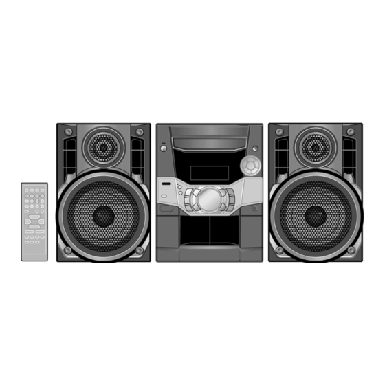
SA-AK110P
Colour
(K)... Black Type
TAPE SECTION :
SG-2W MECHANISM SERIES
Record/playback
Erasure
Motor
Recording system
Erasing system
Tape speed
Overall frequency response (+3 dB, -6 dB at DECK OUT)
NORMAL (TYPE I)
S/N
Wow and flutter
Fast forward and rewind time
CD SECTION
Sampling frequency
Decoding
Beam source/wave length
Number of channels
Frequency response
Wow and flutter
Digital filter
D/A converter
GENERAL
Power supply
Power consumption
Power Consumption in standby
mode
© 2002 Matsushita Electronics (S) Pte. Ltd. All rights
reserved. Unauthorized copying and distribution is a
violation of law.
ORDER NO. MD0211231C1
CD Stereo System
Solid permalloy head
Double gap ferrite head
DC servo motor
AC bias 100 kHz
AC erase 100 kHz
4.8 cm/s (1 7/8 ips)
35 Hz - 14 kHz
50 dB (A weighted)
0.18 % (WRMS)
Approx. 120 seconds with
C-60 cassette tape
44.1 kHz
16 bit linear
Semiconductor laser/780 nm
20 Hz - 20 kHz (+1, -2 dB)
Below measurable limit
MASH (1 bit DAC)
AC 120 V, 60Hz
A6
Stereo
8 fs
165 W
0.34 W
Advertisement
Table of Contents

Related Manuals for Panasonic SA-AK110P


Summary of Contents for Panasonic SA-AK110P
-
Page 1: Specifications
ORDER NO. MD0211231C1 CD Stereo System SA-AK110P Colour (K)... Black Type TAPE SECTION : SG-2W MECHANISM SERIES Specifications AMPLIFIER SECTION Record/playback Solid permalloy head Power output Erasure Double gap ferrite head 10% Total harmonic distortion Motor DC servo motor 60Hz-16kHz, both channels driven... -
Page 2: Table Of Contents
SA-AK110P / Dimensions (W x H x D) 250 x 330 x 370 mm Notes: (9 27/32” x 13” x 14 3/8 “) 1. Specifications are subject to change without notice. Mass and dimensions are aproximate. Mass 7.0 kg (15.4 lb.) 2. -
Page 3: Safety Precaution
SA-AK110P / 1 Safety Precaution (This “Safety Precaution” is applied only in U.S.A.) 1. Before servicing, unplug the power cord to prevent an electric shock. 2. When replacing parts, use only manufacturer’s recommended components for safety. 3. Check the condition of the power cord. Replace if wear or damage is evident. -
Page 4: Protection Circuitry
SA-AK110P / 3 Protection Circuitry The protection circuitry may have operated if either of the following conditions are noticed: • No sound is heard when the power is turned on. • Sound stops during a performance. The function of this circuitry is to prevent circuitry damage if, for example, the positive and negative speaker connection wires are “shorted”, or if speaker systems with an impedance less than the indicated rated impedance of the amplifier are used. -
Page 5: Handling Precautions For Traverse Deck
SA-AK110P / 5 Handling Precautions For Traverse Deck The laser diode in the traverse deck (optical pickup) may break down due to potential difference caused by static electricity of clothes or human body. So, be careful of electrostatic breakdown during repair of the traverse deck (optical pickup). -
Page 6: Precaution Of Laser Diode
SA-AK110P / 6 Precaution of Laser Diode CAUTION: This unit utilizes a class 1 laser. Invisible laser radiation is emitted from the optical pickup lens. When the unit is turned on: 1. Do not look directly into the pick up lens. -
Page 7: Operation Procedures
SA-AK110P / 7 Operation Procedures... -
Page 8: Operation Checks And Component Replacement Procedures
SA-AK110P / 8 Operation Checks and Component Replacement Procedures “ATTENTION SERVICER” Some chassis components may have sharp edges. Be careful when disassembling and servicing. 1. This section describes procedures for checking the operation of the major printed circuit boards and replacing the main components. - Page 9 SA-AK110P / 8.1. Checking for Main P.C.B. • Checking the Main P.C.B. as shown below. Step 1 Remove 3 screws each side and 5 screws at rear panel. Step 2 Lift up both sides of cabinet ass’y, push the cabinet ass’y toward the rear and remove the cabinet ass’y.
- Page 10 SA-AK110P / Step 5 Press the POWER button to turn the power on. Step 6 Press the OPEN/CLOSE button, the disc tray will be close. Step 3 Release the 2 claws, and then remove the CD lid cover. [Open the disc tray manually (Using service tools)] Step 1 Upset the unit as shown below.
- Page 11 SA-AK110P / Step 4 Upset the CD changer unit. Step 5 Place the CD changer unit on the unit. <The preparation of checking procedures in operational condition is completed> 8.3. Checking for the unit operational condition (Place the unit horizontally when loading the CD changer unit.) 8.3.1.
- Page 12 SA-AK110P / • Check the CD Servo P.C.B. as shown below disc tray. (Then, the CD will load.) <The initial setting of CD unit is completed.> Step 6 Lay the unit. 8.3.2. Checking for the CD Servo P.C.B., Panel P.C.B., Deck P.C.B., Transformer P.C.B.
- Page 13 SA-AK110P / • Checking the Power P.C.B. as shown below Step 6 Remove 2 screws. • Follow the (Step 1) - (Step 2) of Item 8.1. Step 7 Release the 2 claws, and then draw the front panel ass’y. • Follow the (Step 1) - (Step 6) of Disassembly for the CD Lid •...
- Page 14 SA-AK110P / 8.3.3. Replacement of the Power Step 4 Unsolder the terminals of Power Amp IC, transistor and replace the component. Amplifier IC • Checking the Power P.C.B. • Follow the (Step 1) - (Step 2) of Item 8.1. Step 1 Remove the 2 screws fixed to the Power Amplifier IC.
- Page 15 SA-AK110P / Step 6 With pressing the claw (A), rotate the hexagonal wrench clockwise. (The slide plate R moves for a little amount.) Step 7 Pressing the claw (B) in the direction of arrow (1), the connection lever moves in the direction of arrow (2).
- Page 16 SA-AK110P / Note: Be careful not to lose the 3 floating spring because those will also be removed on removal of the traverse deck ass’y. Step 12 Remove the FFC board from the connector, and then remove the CD Servo P.C.B.
- Page 17 SA-AK110P / • Installation of the CD Servo P.C.B. after replacement Step 1 Connect the FFC board. Step 2 Install the CD servo P.C.B. in the traverse deck ass’y. Step 3 Remove 3 screws. Step 4 Solder. Step 3 Force the claw of timing lever.
- Page 18 SA-AK110P / 8.5. Replacement for the disc tray • Follow the (Step 1) - (Step 2) of Item 8.1 • Follow the Disassembly for the CD Lid of Item 8.2.1. • Follow the Disassembly for the CD Changer Unit of Item 8.2.2.
- Page 19 SA-AK110P / NOTE: Step 9 With forcing the left guide bar manually because the left guide bar interfers with claw, draw the disc tray. Force the right guide bar of tray base manually not to move upwards. [Installation of the disc tray after replacement] Step 4 Holding the disc tray manually, push the disc tray in the direction of the arrow.
- Page 20 SA-AK110P / 8.6. Disassembly and reassembly for mechanism base drive unit • Follow the (Step 1) - (Step 2) of Item 8.1. • Follow the Disassembly for the CD Lid of Item 8.2.1. • Follow the Disassembly for the CD changer unit of Item 8.2.2.
- Page 21 SA-AK110P / Step 11 Lift up the left end of spindle base unit in the direction of arrow (1), and then remove the unit in the direction of arrow (2). Step 9 Pressing the claw (B) in the direction of arrow (1), force the connection lever in the direction of arrow (2).
- Page 22 SA-AK110P / Step 3 Rotate the disc lever in the direction of arrow (1), draw the disc lever. Step 13 Remove the traverse relay gear, traverse cam gear and drive gear. [Dissassembly/reassembly for the spindle base unit] Step 1 Draw the 5 disc spacers.
- Page 23 SA-AK110P / NOTE: Hold the loading stopper ass’y manually bacause it is flipped by spring. Step 8 Release the 2 claws, and then remove the relay gear A. Step 9 Release the 2 claws, and then remove the spindle shaft.
- Page 24 SA-AK110P / spread the hold bars of loading stopper and remove the UP/DOWN base. [Installation for loading stopper ass’y] Step 1 Align the claw of loading stoppers ass’y with the slot of spindle base. (Caution should be exercised when alignment of claw due to the size of claws.)
- Page 25 SA-AK110P / Step 1 Install the traverse cam gear. Step 2 Rotate the traverse cam gear to the direction of arrow. Step 4 Install the slide plate 2 to the mechanism base, and Step 3 Install the drive gear and traverse relay gear.
- Page 26 SA-AK110P / Step 7 Move the slide plate 1 to forward fully. Step 8 Install the rear lock. (The claw should be latched.) Step 9 Install the bottom SW P.C.B.. (The claw should be latched.) Step 10 Install the tray lock. (The claw should be latched.) Step 11 Remove the tray lock spring from hook,and then latch to the tray lock.
- Page 27 SA-AK110P / Step 14 Install the tray base, traverse ass’y, mechanism cover and upper plate. [Operation check after servicing] Check the proper operation of following items with gear and hexagonal screwdriver. 1. Open/close of tray base. 2. Moving the tray base to the stock side.
- Page 28 SA-AK110P / 1. Locate the name plate of motor to the traverse ass’y. 2. Align the hole of motor with the ribs. 8.8. Replacement for the pinch roller ass’y and head block • Follow the (Step 1) - (Step 2) of Item 8.1.
- Page 29 SA-AK110P / Step 9 Tilt the cassette mechanism in the direction of arrow (1), and then remove it in the direction of arrow (2). Step 10 Unsolder the motor terminals. Step 11 Remove 4 screws. Step 13 Release the 2 claws, and then remove the pinch roller Step 12 Remove mechanism Deck P.C.B.
- Page 30 SA-AK110P / Step 5 Remove the flywheel R. Step 6 Release the claw of tape side, and then remove the winding lever and spring. Step 7 Remove the flywheel F. [Installation of the belt] Step 1 The boss and marking should be positioned horizontally.
- Page 31 SA-AK110P / Step 7 Put the capstan belt A temporarily as shown below. Step 2 Put the winding belt on the pulley temporarily. Step 3 Install the flywheel F. Step 4 Put the winding belt on the flywheel F. Step 5 Install the winding lever and spring while pressing the winding arm in the direction of arrow.
- Page 32 SA-AK110P / 8.10. Replacement for the CD motor ass’y, capstan belt A, capstan belt B and winding belt • Follow the (Step 1) - (Step 2) of Item 8.1. • Follow the Disassembly for the CD Lid of Item 8.2.1.
- Page 33 SA-AK110P / 8.11. Replacement for the cassette lid ass’y • Follow the (Step 1) - (Step 2) of Item 8.1. Step 1 Force the lever upward, open the cassette lid ass’y. (For DECK1 and DECK2) Step 2 Lift up the cassette lid ass’y in the direction of arrow.
- Page 34 SA-AK110P / 8.12. Measure for tape trouble • Follow the (Step 1) - (Step 2) of Item 8.1. Step 1 If a cassette tape cannot be removed from the deck since the tape is caught by the capstan or pinch roller during playback or recording, rotate the flywheel F in the direction of the arrow to remove the tape.
-
Page 35: Self-Diagnostic Function
SA-AK110P / 9 Self-Diagnostic Function 9.1. Self-diagnostic display This unit is equipped with a self-diagnostic display function which, if a problem occurs, will display an error code corresponding to the problem. Use this function when performing maintenance on the unit. -
Page 36: Description Of Error Code
SA-AK110P / 9.4. CD Mechanism Test (F15, F26, F16, F17, F27, F28, F29, H15) 1. Press “CD”. 2. Press “OPEN/CLOSE (1)” and place a CD. 3. Press “OPEN/CLOSE (1)” to close the tray. 4. Press “OPEN/CLOSE (5)” and wait until the tray is open. -
Page 37: Cd Test Mode Function
SA-AK110P / 11 CD Test Mode Function This CD test mode is provided to check CD unit without connecting to changer loading mechanism. This mode shall operate CD PLAY with CD unit being connected only and CD Automatic Alignment result is shown on FL display. -
Page 38: Measurements And Adjustments
SA-AK110P / 12 Measurements and Adjustments 3. Measure and make sure that the output is within the 12.1. Cassette Deck Section standard value. • Measurement Condition Bias voltage for Deck 2 14±4mV (Normal) − Make sure head, capstan and press roller are clean. -
Page 39: Alignment Points
SA-AK110P / 9. Set AM-SG to 520kHz. 10. Receive 520kHz in the unit. 11. Adjust Z101 (OSC) so that the EVM-DC value is with 1.1±0.5V. Fig.2 12.2.2. AM RF Adjustment 1. Connect the instrument as shown in Fig. 3. 2. Set the unit to AM mode. -
Page 40: Illustration Of Ic's, Transistors And Diodes
SA-AK110P / 13 Illustration of IC’s, Transistors and Diodes RSN35H2-P C2BBGF000404 (100P) C0GAM0000005 C0AABB000117 AN7348S-E1 (24P) MN662790RSC (80P) AN8885SBE1 (28P) BU2090AF-E2 (16P) C1BB00000747 (42P) LA1833NMNTLM (24P) LC72131MDTRM (20P) CNB13030R2AU AN8739SBTE2 C1AA00000612 2SK544F-AC KRA102MTA KRA110MTA KRC102MTA KRC103MTA 2SC2058SPTA 2SC2412KT96R KTC2026 2SB621ARSTA... -
Page 41: Terminal Function Of Ic's
SA-AK110P / 14 Terminal Function of IC’s 14.1. IC701 (AN8885SBE1) Servo Pin No. Mark Function SQCK External clock signal input for sub- Amplifier code Q resistor SUBQ sub-code Q code output Pin No. Mark Function DMUTE Mutting input (“H” : mute) - Page 42 SA-AK110P / Pin No. Mark Function Pin No. Mark Function SBCK Clock input for sub-code serial Motor driver (3) reverse-action data output Crystal oscillating circuit input (f = 16.9344MHz) X1 IN Crystal oscullating circuit input (f = 16.9344MHz) Motor driver (4) reverse-action...
- Page 43 SA-AK110P / Pin No. Mark Function CHG_CW Changer motor CW output CHG_ Changer half drive output HALF CHG_ Changer plunger output PLGR CHG_SW2 CD changer SW2 input CHG_SW1 CD changer SW1 input RESTSW CD limit SW input for the most...
-
Page 44: Block Diagram
SA-AK110P / 15 Block Diagram CD OPTICAL PICKUP IC701 AN8885SBE1 SERVO AMP SEMICONDUCTOR LASER RFEQ1 OFTR OFTR Q701 LASER POWER DRIVE TENV RFEQ2 /RFDET /RFDET DET. VREF FEOUT SUBTRACTER VREF TEOUT SUBTRACTER VREF BAND PHOTO DETECTOR VREF FOCUS COIL [CH4]... - Page 45 SA-AK110P / TO MAIN UNIT IC702 MN662790RSC SERVO PROCESSOR/ DIGITAL SIGNAL PROCESSOR DIGITAL FILTER/ D/A CONVERTER CLVS MAIN UNIT OUTR BLKCK BLKCK /CLDCK SBCK SUBC MAIN UNIT DEMPH OUTL CD SIGNAL SSEL FLAG SQCK SQCK IPFLAG SUBQ SUBQ DIGITAL AUDIO...
- Page 46 SA-AK110P / AM ANT FM ANT Z101 Z120 (FM) CF201 CF202 Q101 COIL COIL MIXER IF AMP RF AMP BUFFER (FM) DECODER RM AMP BUFFER PILOT PHASE CANCEL STEREO LEVEL S-CURVE SWITCH AM/FM COMP BUFFER TUNING DRIVE PILOT Z102 IC101...
- Page 47 SA-AK110P / C0GAM0000005 MOTOR DRIVE Vs 8 OUT1 OUT2 POWER SUPPLY CONTROL Q322 CD STATUS STATUS INTERFACE SWITCH Q321 SUBQ SUBQ INTERFACE SWITCH D323 SQCK/ST/DO Q320 Q324 BLKCLK BLKCK CD MOTOR INTERFACE SUPPLY SWITCH SWITCH /CDRST Q323 PLUNGER MOTOR SUPPLY CONTROL...
- Page 48 SA-AK110P / IC1001 AN7348S-E1 P.B. EQ /REC AMP/ ALC/TPS AMP (DECK 1) P.B. HEAD LCH 24(23) Q1014(Q1015) 1(2) 20(5) BUFFER 22(3) 21(4) (DECK 2) R/P HEAD LCH 17(8) 18(7) LOGIC L/H Q1012 Q1020 (Q1013) (Q1021) NOR/CrO & MUTING HI/LO LOGIC...
- Page 49 SA-AK110P / IC301 IN B1 C0AABB000117 HEADPHONE AMP IN B2 3 (5) (24) 1 (7) OUT1(2) Q401 (Q201) 5(38) IN C1(2) Q407 SWITCH (Q207) Q402 (Q202) MUTING HP_L(R) SWITCH MUTING IC300 SWITCH C1BB00000747 8(35) AUDIO SOUND REC1(2) PROCESSOR R445(R245) JK300...
- Page 50 SA-AK110P / (13) OUT_L(R) +IN_L(R) JK952 FULL RANGE (14) -IN_L(R) IC501 RSN35H2-P -VCC +VCC IN GND AC DET LATCH -VCCM FILTER FILTER Q502,Q505 Q512,Q513 VOLTAGE SUPPLY DC_DET SWITCH SWITCH/CURRENT Q501 CONTROL SWITCH JK601 10V VOLTAGE HEADPHONE REGULATOR HP_SW Q514 HEADPHONE...
-
Page 51: Schematic Diagram
SA-AK110P / 16 Schematic Diagram • Importance safety notice : (All schematic diagrams may be modified at any time with the development of the new technology) Components identified mark have special Note: characteristics important for safety. Furthermore, special parts which have purposes of fire-retardant (resistors), high-... - Page 52 SA-AK110P / SCHEMATIC DIAGRAM -1 : +B SIGNAL LINE : CD-DA SIGNAL LINE OPTICAL PICKUP CIRCUIT CD SERVO CIRCUIT R701 LASER DIODE C701 6.3V33 Q701 Q701 B1ADCF000001 C703 LASER POWER DRIVE 6.3V100 R750 LD GND NBOUT C704 C714 6.3V100 C707 0.027...
- Page 53 SA-AK110P / SCHEMATIC DIAGRAM - 2 : +B SIGNAL LINE : CD-DA SIGNAL LINE : CD SIGNAL LINE CD SERVO CIRCUIT R717 C727 C725 50V1 1000P R721 C726 C731 1000P 6.3V220 C730 R718 C728 50V1 C754 C732 C733 470P 6.3V220 LCH OUT A.GND...
- Page 54 SA-AK110P / SCHEMATIC DIAGRAM - 3 : +B SIGNAL LINE : FM SIGNAL LINE : AM SIGNAL LINE : FM/AM SIGNAL LINE : FM OSC SIGNAL LINE : AM OSC SIGNAL LINE TUNER/MAIN CIRCUIT Q106 TUNER PACK Z120 (RAL0029) R104...
- Page 55 SA-AK110P / SCHEMATIC DIAGRAM - 4 : +B SIGNAL LINE : RECORD SIGNAL LINE : AUX SIGNAL LINE : MAIN SIGNAL LINE : FM/AM SIGNAL LINE : PLAYBACK SIGNAL LINE PANEL CIRCUIT (CP601) ON SCHEMATIC DIAGRAM-9 MAIN CIRCUIT CN303 17 16 15 14 13 12 11 10...
- Page 56 SA-AK110P / SCHEMATIC DIAGRAM - 5 : +B SIGNAL LINE : AUX SIGNAL LINE : CD SIGNAL LINE : MAIN SIGNAL LINE PANEL CIRCUIT (CP602) ON SCHEMATIC DIAGRAM-9 MAIN CIRCUIT CN302 10 11 12 13 14 15 16 17 18 19 20 21 22...
- Page 57 SA-AK110P / SCHEMATIC DIAGRAM - 6 : +B SIGNAL LINE : AUX SIGNAL LINE : MAIN SIGNAL LINE : FM/AM SIGNAL LINE : CD SIGNAL LINE : PLAYBACK SIGNAL LINE : RECORD SIGNAL LINE MAIN CIRCUIT D301 UDZSTE177R5B C302 D301 0.01...
- Page 58 SA-AK110P / SCHEMATIC DIAGRAM - 7 : +B SIGNAL LINE : MAIN SIGNAL LINE PANEL CIRCUIT SYS6V R600 4.7K VREF+ R681 IC601 R602 BU2090AF-E2 R601 R603 R604 R605 H_DECK1 1.2K 1.8K 2.2K I/O EXPANDER C636 SW5V R623 4.7K REC_H R622 4.7K...
- Page 59 SA-AK110P / SCHEMATIC DIAGRAM - 8 : +B SIGNAL LINE : -B SIGNAL LINE PANEL CIRCUIT FL600 R656 R657 A2BD00000063 1 2 3 4 5 8 9 10 11 12 13 14 15 16 17 18 19 20 21 22 23 24 25 26 27 28 29 30 31 32 33 34 35 36 37 38 39 40 41 42 43 44 45...
- Page 60 SA-AK110P / SCHEMATIC DIAGRAM - 9 : +B SIGNAL LINE : -B SIGNAL LINE : MAIN SIGNAL LINE PANEL CIRCUIT Q603 Q604 D613 KTA1276GRTA KTA1276GRTA B0BA6R600008 TRANSFORMER DECK SUPPLY SWITCH VREF SUPPLY SWITCH Z600 L601 CIRCUIT B3RAB0000025 SYS6V SYS6V G0C100JA0030...
- Page 61 SA-AK110P / SCHEMATIC DIAGRAM -10 : +B SIGNAL LINE : PLAYBACK SIGNAL LINE : -B SIGNAL LINE : RECORD SIGNAL LINE DECK CIRCUIT R1038 R1039 R1055 4.7 K 2.2K C1038 220P R1098 C1044 R1015 C1034 10V33 50V3.3 C1032 IC1001 0.018...
- Page 62 SA-AK110P / SCHEMATIC DIAGRAM - 11 : +B SIGNAL LINE : PLAYBACK SIGNAL LINE : -B SIGNAL LINE : RECORD SIGNAL LINE MAIN CIRCUIT (CN304) ON SCHEMATIC DIAGRAM-4 DECK CIRCUIT CN1001 Q1017 KTD1146YTA 50V3.3 C1054 MOTOR SWITCH C1064 50V3.3 R1091 R1095 2.2K...
- Page 63 SA-AK110P / SCHEMATIC DIAGRAM - 12 : +B SIGNAL LINE : -B SIGNAL LINE : MAIN SIGNAL LINE POWER CIRCUIT IC501 IC501 RSN35H2-P C501 0.01 C240 R450 470P 330K C443 C442 100V10 C450 470P GND_L GND_R C440 C441 R250 820P...
- Page 64 SA-AK110P / SCHEMATIC DIAGRAM - 13 : +B SIGNAL LINE : -B SIGNAL LINE TRANSFORMER CIRCUIT D950-D953 1N5402BM21 VCC+ D952 D950 VCC- POWER C960 CIRCUIT AC GND (H950/ W950) ON D953 D951 SCHEMATIC T950 AC_IN G4C7AGD00009 DIAGRAM-12 RL950 RSY0040M-0 SUB+B...
-
Page 65: Printed Circuit Board
SA-AK110P / 17 Printed Circuit Board Note: Circuit board diagrams may be modified at any time with the development of new technology. - Page 66 SA-AK110P / CD SERVO P.C.B (REPX0192D) (RF) TP20 X701 TJ701 TP23 C717 TP19 R714 TP21 TP29 C716 C721 R709 C744 TP24 C722 R712 TP18 C723 C724 R742 C725 TP25 IC701 TP26 TP27 C731 C753 TP22 C754 C711 J702 C718 C712...
- Page 67 SA-AK110P / MAIN P.C.B (REPX0325B) FM ANT AM ANT 75 OHMS JK101 C332 C331 R202 R401 J131 J130 Z120 C107 J366 R112 J350 C421 R454 J100 R433 R423 Q401 C440 R432 R318 R429 R460 D401 Q402 Z101 R426 Q301 R424...
- Page 68 SA-AK110P / PANEL P.C.B. (REPX0359A) S606 OPEN/CLOSE S607 R607 S611 S608 FL600 C641 J901 R611 J665 R609 R610 D613 J609 S610 S609 J929 R627 J666 Q611 J667 R657 C603 R656 Q612 J957 J920 J689 J956 Q613 J645 J644 R911 J955...
- Page 69 SA-AK110P / D600 S601 POWER SENSOR C642 R619 R618 R617 IC601 Q610 Z600 Q611 J621 Q609 CP601 Q612 J949 R917 J942 J646 C639 J948 Q613 R605 R911 J684 R919 S602 R687 R916 J940 R920 SSEQ S605 R604 J672 J647 J618...
- Page 70 SA-AK110P / TACT SWITCH P.C.B. (REPX0359A) VOLUME R902 S902 S903 R903 S901 S904 TUNER CD PLAY VR600 J932 S910 S905 R909 STOP DISPLAY R908 R905 S909 S906 CP900 S907 S908 R907 R906 DECK1 OPEN DECK2 OPEN TAPE...
- Page 71 SA-AK110P / DECK P.C.B. DECK MECHANISM P.C.B. (REPX0331A) (REPX0321A) Q1001 IC1004 C1006 R1006 C1009 R1005 C1003 J1000 CS1002 TP10 J1002 L1002 TP11 R1001 Q1007 R1004 TP12 C1002 J1003 C1026 C1021 C1020 C1011 C1016 R1010 R1009 C1022 C1010 R1028 C1014 C1041...
- Page 72 SA-AK110P / POWER P.C.B. (REPX0328B) C513 R516 J513 J511 R509 J510 J512 D508 R508 C514 R531 R507 R532 R515 D507 D505 J543 R529 C512 R530 J541 D509 J567 R521 D503 J501 J576 J523 J566 R522 J553 J542 C510 R511 C540...
- Page 73 SA-AK110P / TRANSFORMER P.C.B. (REPX0324C)
- Page 74 SA-AK110P / CD LOADING P.C.B (REP2578A-N) 1 2 3 4 5 6 7 8 9 10 2 3 4 CD DETECT P.C.B SPINDLE POSITION P.C.B (REP2578A-N) (REP2578A-N) 1 2 3 4 TUNER PACK P.C.B (REP1999B)
-
Page 75: Wiring Connection Diagram
SA-AK110P / 18 Wiring Connection Diagram FM ANT AM ANT SOLDER SIDE H950/W950 JK300 JK101 CD LOADING P.C.B CN501 TUNER PACK CN300 P.C.B SOLDER SIDE Z102 Z120 CD DETECT P.C.B SOLDER SIDE CN309 13 14 POWER P.C.B MAIN P.C.B SOLDER SIDE... -
Page 76: Troubleshooting Guide
SA-AK110P / 19 Troubleshooting Guide... -
Page 77: Parts Location And Replacement Parts List
SA-AK110P / 20 Parts Location and Replacement Parts List Notes: • Important safety notice: Components identified by mark have special characteristics important for safety. Furthermore, special parts which have purposes of fire-retardent (resistors), high-quality sound (capacitors), low noise (resistors), etc are used. - Page 78 SA-AK110P / 20.1. Deck Mechanism (RAA4502-S) 20.1.1. Deck Mechanism Parts Location...
- Page 79 SA-AK110P /...
-
Page 80: Deck Mechanism Parts List
SA-AK110P / 20.1.2. Deck Mechanism Parts List Ref. No. Part No. Part Name & Description Remarks CASSETTE DECK RED0069 R/P HEAD BLOCK UNIT RED0070 P/B HEAD BLOCK UNIT RDG0300 REEL BASE GEAR RDG0301 WINDING RELAY GEAR RDK0026 MAIN GEAR RDV0033-4... - Page 81 SA-AK110P / 20.2. CD Loading Mechanism (RD-DAC026-S) 20.2.1. CD Loading Mechanism Parts Location...
- Page 82 SA-AK110P /...
-
Page 83: Cd Loading Mechanism Parts List
SA-AK110P / 20.2.2. CD Loading Mechanism Parts List Ref. No. Part No. Part Name & Description Remarks Ref. No. Part No. Part Name & Description Remarks TRAVERSE DECK XTN2+6G SCREW RMX0141 PUSH SPACER RML0517 TIMING LEVER RMQ0749 UPPER SPINDLE RML0516... - Page 84 SA-AK110P / 20.3. Cabinet 20.3.1. Cabinet Parts Location...
- Page 85 SA-AK110P /...
- Page 86 SA-AK110P /...
-
Page 87: Cabinet Parts List
SA-AK110P / 20.3.2. Cabinet Parts List Ref. No. Part No. Part Name & Description Remarks Ref. No. Part No. Part Name & Description Remarks CABINET AND CHASSIS RKFX0093-KM CASS HOLDER L RKFX0094-KM CASS HOLDER R REEX0202 10P FFC RKMX0077A-K TOP CABINET (BENT) - Page 88 SA-AK110P / Ref. No. Part No. Part Name & Description Remarks Ref. No. Part No. Part Name & Description Remarks Q701 B1ADCF000001 TRANSISTOR D961 1D3E DIODE Q950 KTC3205YTA TRANSISTOR D962 1D3E DIODE Q951 2SB621ARSTA TRANSISTOR D963 1D3E DIODE Q952 KRC102MTA...
- Page 89 SA-AK110P / Ref. No. Part No. Part Name & Description Remarks Ref. No. Part No. Part Name & Description Remarks CP602 K1MN30A00046 30P CONNECTOR JK300 RJH2213N-2 JK 2P RCA CP900 RJU066H08 8P B-B SOCKET JK601 RJJ37TK07-X JK HEADPHONE JK950 K2AB2B000002...
- Page 90 SA-AK110P / Ref. No. Part No. Part Name & Description Remarks Ref. No. Part No. Part Name & Description Remarks R152 ERJ3GEY0R00V 0 1/16W R327 ERJ3GEYJ103V 10K 1/16W R201 ERJ3GEYJ103V 10K 1/16W R328 ERJ3GEYJ562V 5.6K 1/16W R202 ERJ3GEYJ332V 3.3K 1/16W...
- Page 91 SA-AK110P / Ref. No. Part No. Part Name & Description Remarks Ref. No. Part No. Part Name & Description Remarks R451 ERDS2TJ104T 100K 1/4W R628 ERDS2TJ101T 100 1/4W R451 ERJ3GEYJ333V 33K 1/16W R629 ERDS2TJ101T 100 1/4W R452 ERJ3GEYJ104V 100K 1/16W...
- Page 92 SA-AK110P / Ref. No. Part No. Part Name & Description Remarks Ref. No. Part No. Part Name & Description Remarks R750 ERJ6GEYJ4R7V 4.7 1/10W R1049 ERJ3GEYJ105V 1M 1/16W R753 D0GB100JA002 100 1/16W R1050 ERJ3GEYJ105V 1M 1/16W R900 ERDS2TJ103T 10K 1/4W...
- Page 93 SA-AK110P / Ref. No. Part No. Part Name & Description Remarks Ref. No. Part No. Part Name & Description Remarks C136 ECJ1VB1H102K 1000P 50V C403 ECJ1VB1H102K 1000P 50V C137 ECUV1H332KBV 3300P 50V C404 ECUV1H221KBV 220P 50V C138 ECJ1VB1E103K 0.01 25V...
- Page 94 SA-AK110P / Ref. No. Part No. Part Name & Description Remarks Ref. No. Part No. Part Name & Description Remarks C617 ECBT1H180JC5 18P 50V C954 ECKR1H103ZF5 0.01 50V C618 ECBT1H150JC5 15P 50V C955 ECA1HM101B 100 50V C620 F1D1E223A001 0.022 25V...
- Page 95 SA-AK110P / Ref. No. Part No. Part Name & Description Remarks Ref. No. Part No. Part Name & Description Remarks RJ724 ERJ3GEY0R00V 0 1/16W RJ736 ERJ3GEY0R00V 0 1/16W RJ725 ERJ3GEY0R00V 0 1/16W RJ737 ERJ3GEY0R00V 0 1/16W RJ726 ERJ3GEY0R00V 0 1/16W...